2014 MITSUBISHI OUTLANDER ignition
[x] Cancel search: ignitionPage 131 of 451

Steering wheel height
and reach adjustment
Features and controls 5-53
5
When parking on a hill, set the parking brake, and turn the front wheels toward the curb on a downhill, or away from
the curb on an uphill.
N00511501241
To adjust the steering wheel to the desired position, move the lever upward or down- ward while moving the steering wheel to the desired position.
To apply 1- Pull the lever up without pushing the
button at the end of hand grip. When the parking brake is set and theignition switch is in the “ON” position, the brake warning light in the instru- ment cluster will come on. Before driving, be sure to release the parking brake.
To deactivate 1- Pull the lever up slightly. 2- Press and hold the button at the end of
the hand grip.
3- Push the lever downward.
CAUTION Before driving, be sure that the parking brake is fully released and brake warninglight is off.If you drive without the parking brake fully released, the warning di
splay will appear on
the information screen in the multi-informa-tion display. If a vehicle is driven without releasing the parking brake, the brak
es will be overheated,
resulting in ineffectiv
e braking and possible
brake failure. Warning light Warning display
Steering wheel height and reach adjustment
BK0200500US.book 53 ページ 2013年2月12日 火曜日 午前9時46分
Page 133 of 451

Outside rearview mirrors
Features and controls 5-55
5
N00512201232
Adjust the outside rearview mirrors only after making any seat adjustme
nts so as to have a
clear view to the rear of the vehicle.
N00549101154
The outside rearview mirrors can be adjustedwhen the ignition switch is in the “ON” or
“ACC” position or the
operation mode is put
in ON or ACC.Move the lever (A) to the same side as the mirror you wish to adjust. Press the switch (B) to adjust the mirror posi- tion.
1- Daytime position 2- Night positionOutside rearview mirrors
WA R N I N G Do not attempt to adjust the outside rear- view mirrors while driving. This can be dangerous. Be sure to adjust the mirrors before driv-ing.
Your passenger’s side mirror is convex. The objects you see in
the mirror will look
smaller and farthe
r away than they
appear in a regular flat mirror. Do not use this mirror to estimate the dis- tance of vehicles
following you when
changing lanes.
To adjust the mirror position
WA R N I N G
L- Left outside mirror adjustment R- Right outside mirror adjustment 1- Up 2- Down 3- Right 4- Left
NOTE
After adjusting, return the lever to the “•”(OFF) position (C).
BK0200500US.book 55 ページ 2013年2月12日 火曜日 午前9時46分
Page 134 of 451

Ignition switch 5-56 Features and controls
5
N00549201100
The outside mirror can be folded in towards the side window to prevent damage when parking in tight locations.
N00549301228
When the rear window defogger switch is pressed with the engine running, the outside rearview mirrors are defogged or defrosted.Current will flow throug
h the heater element
inside the mirrors, thus clearing away frost or condensation.The indicator light (A) will illuminate while the defogger is on. The heater will be turned off automatically inabout 15 to 20 minutes depending on the out- side temperature.
N00512401696
[For vehicles equipped with the Free-hand Advanced Security Tr
ansmitter (F.A.S.T.-
key).] For information on ope
rations for vehicles
equipped with the Free-hand Advanced Secu- rity Transmitter (F.A
.S.T.-key), refer to
“Free-hand Advanced
Security Transmitter
(F.A.S.T.-key): Engine switch” on page 5-16. [Except for vehicles equipped with the Free-hand Advanced Se
curity Transmit-
ter (F.A.S.T.-key).]
The engine is off a
nd the steering wheel is
locked. The key can be inserted and removed only when the switch is in this position. The engine is off. The
key can be inserted and
removed only when the sw
itch is in this posi-
tion. Allows operation of el
ectrical accessories
with the engine off.
To fold the mirror Door mirror heater
(if so equipped)
Ignition switch
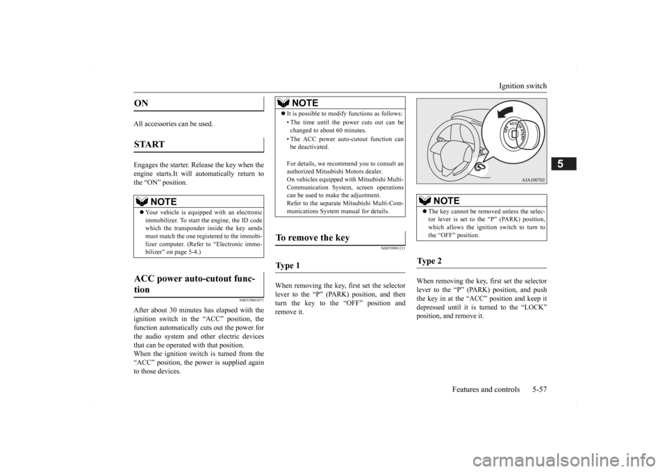
LOCK (Type 2) OFF (Type 1) ACC Type 1 Type 2
BK0200500US.book 56 ページ 2013年2月12日 火曜日 午前9時46分
Page 135 of 451

Ignition switch
Features and controls 5-57
5
All accessories can be used. Engages the starter. Release the key when the engine starts.It will automatically return to the “ON” position.
N00539601071
After about 30 minutes has elapsed with the ignition switch in the “ACC” position, thefunction automatically cuts out the power for the audio system and ot
her electric devices
that can be operated with that position.When the ignition switch is turned from the “ACC” position, the pow
er is supplied again
to those devices.
N00550901211
When removing the key,
first set the selector
lever to the “P” (PARK) position, and then turn the key to the “OFF” position and remove it.
When removing the key, first set the selector lever to the “P” (PARK) position, and push the key in at the “ACC” position and keep it depressed until it is turned to the “LOCK”position, and remove it.
ON START
NOTE
Your vehicle is equippe
d with an electronic
immobilizer. To start
the engine, the ID code
which the transponder inside the key sendsmust match the one registered to the immobi- lizer computer. (Refer to “Electronic immo- bilizer” on page 5-4.)
ACC power auto-cutout func- tion
NOTE
It is possible to modify functions as follows: • The time until the power cuts out can be changed to about 60 minutes. • The ACC power auto
-cutout function can
be deactivated. For details, we reco
mmend you to consult an
authorized Mitsubishi Motors dealer. On vehicles equipped
with Mitsubishi Multi-
Communication System, screen operations can be used to ma
ke the adjustment.
Refer to the separate Mitsubishi Multi-Com-munications System manual for details.
To remove the key Ty p e 1
NOTE
The key cannot be rem
oved unless the selec-
tor lever is set to the “P” (PARK) position,which allows the ignition switch to turn to the “OFF” position.
Ty p e 2
BK0200500US.book 57 ページ 2013年2月12日 火曜日 午前9時46分
Page 136 of 451
![MITSUBISHI OUTLANDER 2014 3.G Owners Manual Steering wheel lock (if so equipped) 5-58 Features and controls
5
N00512501222
[For vehicles equipped with the Free-hand Advanced Security Tr
ansmitter (F.A.S.T.-
key).] For information on ope
rati MITSUBISHI OUTLANDER 2014 3.G Owners Manual Steering wheel lock (if so equipped) 5-58 Features and controls
5
N00512501222
[For vehicles equipped with the Free-hand Advanced Security Tr
ansmitter (F.A.S.T.-
key).] For information on ope
rati](/manual-img/19/7531/w960_7531-135.png)
Steering wheel lock (if so equipped) 5-58 Features and controls
5
N00512501222
[For vehicles equipped with the Free-hand Advanced Security Tr
ansmitter (F.A.S.T.-
key).] For information on ope
rations for vehicles
equipped with the Free-hand Advanced Secu-rity Transmitter (F.A
.S.T.-key), refer to
“Free-hand Advanced
Security Transmitter
(F.A.S.T.-key): Steering wheel lock” on page5-22 [Except for vehicles equipped with the Free-hand Advanced Se
curity Transmit-
ter (F.A.S.T.-key).] (Vehicles with steering lock system)
Remove the key at
the “LOCK” position.
Turn the steering wheel until it is locked. Turn the key to the “ACC” position while moving the steering
wheel slightly.
N00512601799
[For vehicles equipped with the Free-hand Advanced Security Transmitter (F.A.S.T.- key).] For information on operation for vehiclesequipped with the Free-hand Advanced Secu- rity Transmitter (F.A.S.T.-key), refer to
NOTE
The key cannot be rem
oved unless the selec-
tor lever is set to the “P” (PARK) position, which allows the ignition switch to turn tothe “LOCK” position.CAUTION If the engine is stopped while driving, the power brake booster
will stop functioning
and greater effort for braking will be required. Also, the
power steering system
will not function and it
will require greater
effort to manually steer the vehicle. Do not leave the key in
the “ON” position for
a long time when the engine is not running. This will cause the battery to run down. Do not turn the key to the “START” position when the engine is ru
nning. It will damage
the starter motor.
Steering wheel lock
(if so
equipped)
To l o c k
To u n l o c k
CAUTION Remove the key when leaving the vehicle.NOTE
If the front wheels are turned, the anti-theft lock may sometimes make it difficult to turn the key from “LOCK” to “ACC”. Firmlyturn the steering wheel to the left or to the right as you turn the key.
Starting the engine
BK0200500US.book 58 ページ 2013年2月12日 火曜日 午前9時46分
Page 137 of 451

Starting the engine
Features and controls 5-59
5
“Free-hand Advanced
Security Transmitter
(F.A.S.T.-key): Starting” on page5-12. [Except for vehicles equipped with the Free-hand Advanced Security Transmit- ter (F.A.S.T.-key).] Do not operate the starter motor continu- ously for longer than 15 seconds as this could run the battery
down or damage the
starter motor. If the engine does not start, turn the ignition switch back to the “OFF” or “LOCK” position,
wait a few seconds,
and then try again. Trying repeatedly with the engine or starter motor still turning will damage the starter mechanism. If the engine will not
start because the bat-
tery is weak or discharged, refer to “Jump-starting the engine” (on page 8-2)for instructions. A longer warm up period will only con- sume extra fuel. The engine is warmed upenough for driving when the bar graph of engine coolant temper
ature display starts
to move or the low coolant temperatureindicator goes out. Refer to “Engine cool- ant temperature display” on page 5-128 or “Low coolant temper
ature indicator” on
page 5-166.
This model is equipped with an electronically controlled fuel injection system. This is a sys-tem that automatically controls fuel injection. There is usually no need to depress the accel- erator pedal when starting the engine.The starter should not be run for more than 15 seconds at a time. To prevent battery drain, wait a few secondsbetween attempts to restart the engine. 1. Make sure all occupants are properly seated with seat belts fastened.
2. Insert the ignition key. 3. Press and hold the brake pedal down withyour right foot. 4. Make sure the selector
lever is in the “P”
(PARK) position.5. Turn the ignition switch to the “ON” posi- tion and make certain that all warning lights are functioning properly beforestarting the engine. 6. Turn the ignition switch to the “START” position without pressi
ng the accelerator
pedal. Release the ignition switch when the engine starts.
After several attempts, you may experience that the engine still does not start. 1. Make sure that all electric devices, such as lights, air conditio
ning blower and rear
window defogger, are turned off.
Tips for starting
WA R N I N G Never run the engine in
a closed or poorly
ventilated area any longer than is neededto move your vehicle
out of the area. Car-
bon monoxide gas, wh
ich is odorless and
extremely poisonous, could build up and cause serious injury or death.CAUTION Do not push-start the vehicle.Do not run the engine at high rpms or drive at high speeds until
the engine has had a
chance to warm up. Release the ignition sw
itch as soon as the
engine starts. Otherwis
e, the starter motor
will be damaged
Starting the engine
NOTE
Minor noises may be heard on engine start- up. These will disappear as the engine warmsup.
When the engine is hard to start
BK0200500US.book 59 ページ 2013年2月12日 火曜日 午前9時46分
Page 138 of 451

Automatic transaxle (if so equipped) 5-60 Features and controls
5
2. While depressing the brake pedal, press the accelerator peda
l halfway and hold it
there, then crank th
e engine. Release the
accelerator pedal, immediately after the engine starts.3. If the engine still will
not start, the engine
could be flooded with too much gasoline. While depressing the brake pedal, pushthe accelerator pedal all the way down and hold it there, then crank the engine for 5 to 6 seconds. Return the ignition switch to the “OFF” or “LOCK” position and release the accelerator pedal. Wait a fewseconds, and then crank the engine again for 5 to 6 seconds while depressing the brake pedal, but do no
t push the accelera-
tor pedal. Release the ignition key if the engine starts. If the engine fails to start, repeat these procedures
. If the engine still
will not start, cont
act your local Mitsubi-
shi Motors dealer or a repair facility of your choice for assistance.
When the ambient temperature is -22 °F (-30 °C) or lower, it may not be possible to start
from a standstill even wi
th the selector lever
in the “D” (DRIVE) position.This occurs because the transaxle has not warmed up sufficiently
; it does not indicate a
problem. If this occurs, place the selectorlever in the “P” (PAR
K) position and let the
engine idle for at least 10 minutes. The transaxle will wa
rm up, and you will be
able to start normally. Do not leave the vehicle during warm-up operation. The MIVEC engine automatically switches its intake-valve control between a low-speed mode and a high-speed mode in accordance with driving conditions for maximum engineperformance.
N00513200216
Automatic transaxle will automaticallychange its gear depe
nding on road and driv-
ing conditions. This
helps achieve smooth
driving and excellent fuel efficiency. Also you can manually shift up and shiftdown the transaxle. Refer to “Sports mode” on page 5-65. The transaxle prevents
unnecessary upshifts
even when the accelerator pedal is releasedand ensures smooth driving. According to the conditions, the transaxle will automatically shift to a lower gear to achieve stronger engine braking. This may help reduce your need to use the servicebrake.
Startability of automatic transaxle vehicle and CVT vehicle with ambient temperature of -22 °F (-30 °C) or lower
Using the MIVEC engine
NOTE
To protect the engine
, the high-speed mode
may not be selected wh
ile the engine coolant
temperature is low. In such a case, the engine revolutions do not rise to over 5,000 rpmeven if the accelerato
r pedal is depressed.
Automatic transaxle
(if so
equipped)DRIVING UPHILL
DRIVING DOWNHILL
BK0200500US.book 60 ページ 2013年2月12日 火曜日 午前9時46分
Page 146 of 451

Continuously variable transmission (CVT) (if so equipped) 5-68 Features and controls
5
N00560200034
The CVT will automati
cally and continuously
change its gear ratio depending on road anddriving conditions. This helps achieve smooth driving and excellent fuel efficiency. Also you can manually shift up and shiftdown the transmission. Refer to “Sports mode” on page 5-72. The transmission prevents unnecessary upshifts even when the accelerator pedal is released and ensures smooth driving.
According to the condi
tions, the transmission
will automatically shift to a lower gear ratio to achieve stronger engi
ne braking. This may
help reduce your need to use the service brake.
N00560301061
As an additional safe
ty precaution, models
equipped with a continuously variable trans-mission have a shift-lock device that holds the selector lever in the “P” (PARK) position. To move the selector lever from the “P”(PARK) position to another position, follow the steps below. 1. Press and hold the brake pedal down. 2. Move the selector lever to the desiredposition.
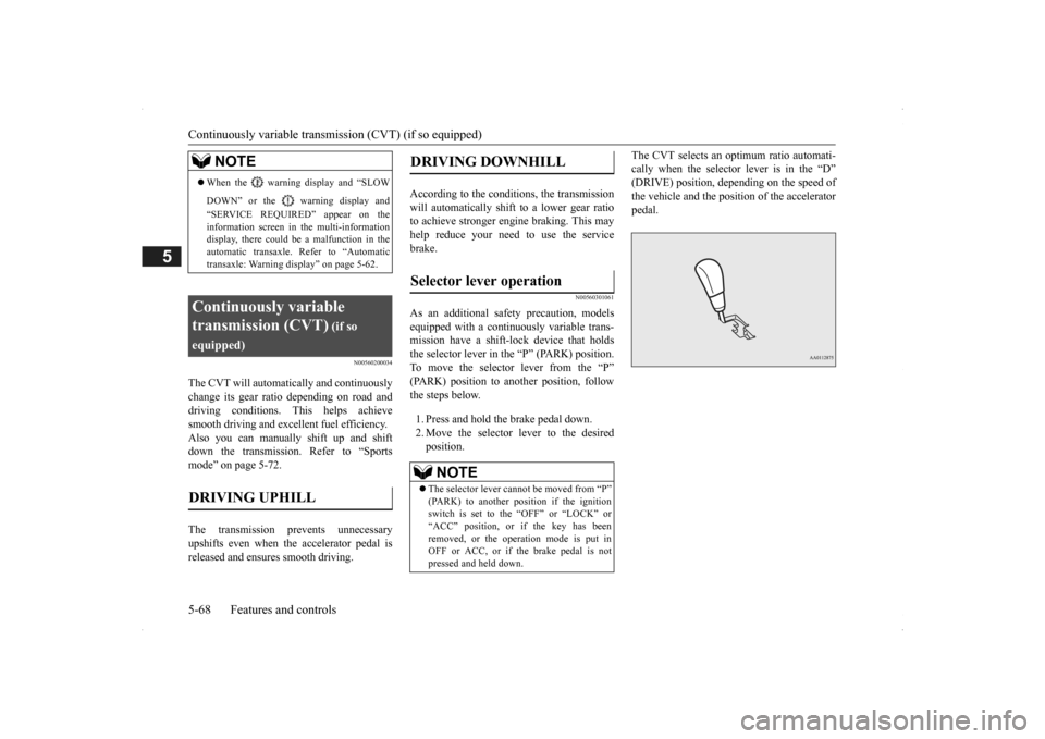
The CVT selects an optimum ratio automati- cally when the selector lever is in the “D”(DRIVE) position, depending on the speed of the vehicle and the posit
ion of the accelerator
pedal.
NOTE
When the warning display and “SLOW DOWN” or the wa
rning display and
“SERVICE REQUIRED” appear on the information screen in the multi-informationdisplay, there could be
a malfunction in the
automatic transaxle. Refer to “Automatic transaxle: Warning di
splay” on page 5-62.
Continuously variable transmission (CVT)
(if so
equipped)DRIVING UPHILL
DRIVING DOWNHILL
Selector lever operation
NOTE
The selector lever cannot
be moved from “P”
(PARK) to another po
sition if the ignition
switch is set to the “OFF” or “LOCK” or“ACC” position, or if the key has been removed, or the opera
tion mode is put in
OFF or ACC, or if the brake pedal is notpressed and held down.
BK0200500US.book 68 ページ 2013年2月12日 火曜日 午前9時46分