2014 MITSUBISHI OUTLANDER bulb
[x] Cancel search: bulbPage 417 of 451

Replacement of light bulbs
Vehicle care and maintenance 9-33
9
N00901801131
1. When replacing the bulb on the left side of the vehicle, remo
ve the bolt (A) hold-
ing down the relay box and move the relay box toward the rear of the vehicle. (if so equipped)
2. Turn the cap (B) counterclockwise to remove it. 3. Turn the socket (C) counterclockwise to remove it, and then pull the bulb out of the socket. 4. To install the bulb, perform the removal steps in reverse.
N00900301139
Do not attempt to disass
emble or repair head-
lights, and do not attempt to replace their bulbs.
Headlights (low beam, except for vehicles equipped with high intensity discharge head- lights)/Daytime running lights
(if so equipped) * - Front of the vehicle
*- Front of the vehicle
Headlights (low beam, for vehi- cles equipped with high inten-sity discharge headlights)
WA R N I N G A high voltage is present in the power cir- cuit and in the bulbs and bulb terminals. To avoid the risk of an electric shock, con-tact an authorized
Mitsubishi Motors
dealer whenever repair or replacement is necessary.
BK0200500US.book 33 ページ 2013年2月12日 火曜日 午前9時46分
Page 418 of 451

Replacement of light bulbs 9-34 Vehicle care and maintenance
9
N00901901099
1. Turn the cap (A) counterclockwise to remove it. 2. Turn the bulb (B) counterclockwise to remove it and then while holding downthe tab (C), pull out the connector (D).
3. To install the bulb, perform the removal steps in reverse.
N00943201359
The alignment of the headlights should bechecked by an authorized Mitsubishi Motorsdealer or a repair fa
cility of your choice.
N00915501171
1. When replacing the bulb on the left side of the vehicle, move
the relay box toward
the rear of the vehicle. (if so equipped)(Refer to “Headlight (low beam, except for vehicles equipped
with high intensity
discharge headlight
s)/Daytime running
light): Step 1” on page 9-33.
2. Turn the socket (A) counterclockwise to remove it, and then pull the bulb out ofthe socket. 3. To install the bulb, perform the removal steps in reverse.
Headlights (high beam) * - Front of the vehicle * - Front of the vehicle
Headlight aim adjustment Front side-marker lights
* - Front of the vehicle
BK0200500US.book 34 ページ 2013年2月12日 火曜日 午前9時46分
Page 419 of 451

Replacement of light bulbs
Vehicle care and maintenance 9-35
9
N00917301577
When replacing the bulb on the left side of the vehicle, move the relay box toward the rear of the vehicle. (if so equipped)(Refer to “Headlight
(low beam, except for
vehicles equipped with
high intensity dis-
charge headlights)/Daytime running light):Step 1” on page 9-33.) 1. Turn the cap (A) counterclockwise to remove it.
2. Pull out the socket (B), and then pull the bulb out of the socket. 3. To install the bulb, perform the removal steps in reverse.
1. Turn the socket (A
) counterclockwise to
remove it, and then pull the bulb out ofthe socket. 2. To install the bulb, perform the removal steps in reverse.
Parking lights Except for vehicles equipped with high intensity discharge headlights *: Front of the vehicle
Vehicles equipped with high inten-sity discharge headlights *: Front of the vehicle
BK0200500US.book 35 ページ 2013年2月12日 火曜日 午前9時46分
Page 420 of 451

Replacement of light bulbs 9-36 Vehicle care and maintenance
9
N00943401380
1. Turn the socket (A) counterclockwise to remove it, then remove the bulb from the socket by turning it counterclockwisewhile pressing in. 2. To install the bulb, perform the removal steps in reverse.
N00943501147 N00943601773
1. Insert a straight blade (or minus) screw- driver with a cloth over its tip at the edge of the cover (A) and pry gently to removethe cover.
2. Remove the 3 screws (B) and remove the light unit.
Front turn signal lights * : Front of the vehicle
Side turn signal lights
(if so
equipped)
NOTE
The side turn signal lights uses an LED instead of the bulb. Check with an authorized Mitsubishi Motors dealer or a repair facility of your choicewhen the light needs to be repaired or replaced.
Front fog lights (if so equipped)/Daytime running lights (if so equipped)
NOTE
When unfastening the screws or the fog light, be careful not to
move the beam posi-
tion adjustment screw (C).
BK0200500US.book 36 ページ 2013年2月12日 火曜日 午前9時46分
Page 421 of 451

Replacement of light bulbs
Vehicle care and maintenance 9-37
9
3. Turn the socket counterclockwise to remove it.
4. While holding down the tab (F), pull out the bulb (G). 5. To install the bulb, perform the removal steps in reverse.
N00943701501
1. Open the liftgate.2. Remove the screws (A), and then move the light unit toward the rear of the vehi-cle to unfix the notch (B) and pins (C).
3. Turn the socket counterclockwise and remove it, and then remove the bulb fromthe socket by turning it counterclockwise while pressing in. 4. To install the bulb, perform the removal steps in reverse.
D- Front fog light E- Daytime running lightType 1 Type 2 Type 3
Rear combination lights Front fog light Daytime running light
D- Tail and stop light E- Rear turn signal light
NOTE
The rear side-marker light uses an LED instead of the bulb. Check with an authorized Mitsubishi Motorsdealer or a repair fa
cility of your choice
when the light needs to be repaired or replaced.
BK0200500US.book 37 ページ 2013年2月12日 火曜日 午前9時46分
Page 422 of 451

Replacement of light bulbs 9-38 Vehicle care and maintenance
9
N00929101064
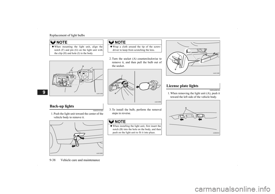
1. Push the light unit toward the center of the vehicle body to remove it.
2. Turn the socket (A
) counterclockwise to
remove it, and then pull the bulb out of the socket. 3. To install the bulb, perform the removal steps in reverse.
N00944000360
1. When removing the light unit (A), push ittoward the left side of the vehicle body.
NOTE
When mounting the light unit, align the notch (F) and pin (G)
on the light unit with
the clip (H) and hole (I) in the body.
Back-up lights
NOTE
Wrap a cloth around the tip of the screw- driver to keep from scratching the lens.NOTE
When installing the light unit, first insert the notch (B) into the hole on the body, and then push on the light unit to fit it into place.
License plate lights
BK0200500US.book 38 ページ 2013年2月12日 火曜日 午前9時46分
Page 423 of 451

Vehicle care precautions
Vehicle care and maintenance 9-39
9
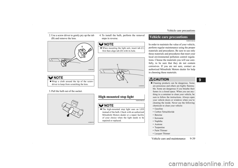
2. Use a screw driver to gently pry up the tab (B) and remove the lens. 3. Pull the bulb out of the socket.
4. To install the bulb, perform the removal steps in reverse.
N00943900102
N00945100166
In order to maintain the value of your vehicle, perform regular mainte
nance using the proper
materials and procedures
. Be sure to use only
those materials and proc
edures that meet your
local environmental pollution control regula- tions. Choose the materials you will use care-fully, to be sure that they do not contain corrosives. If you are
not sure, contact an
authorized Mitsubishi Motors dealer for help in choosing these materials.
NOTE
Wrap a cloth around the tip of the screw- driver to keep from scratching the lens.
NOTE
When mounting the light unit, insert tab (C) first then align tab (D) with its hole.
High-mounted stop light
NOTE
The high-mounted stop light uses an LED instead of the bulb. Check with an authorizedMitsubishi Motors dealer
or a repair facility
of your choice when the light needs to be repaired or replaced.
Vehicle care precautions
CAUTION Cleaning products ca
n be dangerous. Some
are poisonous and others are highly flamma-ble. Some are dangerous if you breathe their fumes in a closed space. When you use any- thing in a container to clean your vehicle, besure to follow the instructions. Always open your vehicle doors or windows when you’re cleaning the inside. Ne
ver use the following
chemicals to clean your vehicle:• Gasoline• Carbon Tetrachloride• Benzine• Kerosene• Naphtha• Acetone• Turpentine• Paint Thinner• Lacquer Thinner
BK0200500US.book 39 ページ 2013年2月12日 火曜日 午前9時46分
Page 443 of 451

Alphabetical index
12-1
12
Numerics
12 V power outlets
............................
5-211
4-wheel drive operation
.......................
5-81
A
Accessory (installation)
.........................
3-6
Active stability control (ASC)
..............
5-90
Adaptive Cruise Cont
rol System (ACC) 5-96
Air bag
..............................................
4-33
Air cleaner filter
...................................
9-9
Air conditioner
Automatic climate control air conditioner
.
7-5Important air condi
tioning operating tips
..
7-14
Air purifier
.........................................
7-14
All-wheel drive operation
....................
5-81
Aluminum wheels
...............................
9-43
AM/FM radio
.....................................
7-15
Antenna
Roof antenna
..................................
7-47
Anti-lock braking system
.....................
5-87
Arm rest
...............................................
4-9
Assist grip
........................................
5-221
Audio
AM/FM radio
.................................
7-15
CD player
......................................
7-15
Troubleshooting
.............................
7-45
Automatic climate cont
rol air conditioner 7-5
Automatic transaxle
............................
5-60
Fluid
.....................................
9-10
, 11-7
Selector le
ver operation
..................
5-61
Selector lever positions
...................
5-64
Sports mode
...................................
5-65
B
Back-up light
Bulb capacity
.................................
9-30
Replacement
..................................
9-38
Ball joint, steering linka
ge seals, drive shaft
boots
...............................................
9-23
Battery
..............................................
9-13
Charging system warning light
.......
5-168
Checking battery
electrolyte level
....
9-13
Disconnection and connection
.........
9-13
During cold weather
.......................
9-13
Specification
..................................
11-6
Bluetooth® 2.0 interface
....................
5-185
Bottle holders
....................................
5-219
Brake
Fluid
.....................................
9-12
, 11-7
Brake assist
........................................
5-86
Braking
Anti-lock braking system
................
5-87
Braking
...........................................
6-5
Hose
..............................................
9-23
Pad wear alarm
...............................
5-85
Parking brake
.................................
5-52
Pedal
.............................................
5-84
Pedal free play
................................
9-21
Power brakes
..................................
5-85
Service brake
..................................
5-84
Warning lights and buzzer
.............
5-167
Break-in recommendations
....................
5-3
Bulb capacity
......................................
9-30
C
California Perchl
orate Materials
Requirements
.....................................
3-7
Capacities
..........................................
11-7
Card holder
............................
5-211
, 5-216
Cargo area cover
...............................
5-219
Cargo loads
........................................
6-10
Cargo room light
...............................
5-214
Bulb capacity
.................................
9-32
Catalytic converter
................................
9-2
Cautions on the handling of all-wheel drive vehicles
............................................
5-83
CD player
...........................................
7-15
Certification label
...............................
11-3
Charging system warning light
...........
5-168
Child restraint systems
........................
4-25
Child safety locks for rear door
............
5-35
BK0200500US.book 1 ページ 2013年2月12日 火曜日 午前9時46分