Page 182 of 460
 are
displayed on the screen.
�Red line (B) indicates approximately 20 inches (50 cm)")
3-94 Features and controls
3
Reference lines on the screenReference lines and upper surface of the rear bumper (A) are
displayed on the screen.
�Red line (B) indicates approximately 20 inches (50 cm)
behind the rear bumper.
�Two Green lines (C) indicate approximately 8 inches (20
cm) outside of the vehicle body.
�Short transverse lines (1 to 3) indicate distance from the
rear bumper.1: Approximately at the rear edge of the rear bumper
2: Approximately 39 inches (100 cm)
3: Approximately 79 inches (200 cm)
CAUTION
!�The rear-view camera uses a wide-angle lens. As a
result, images and distances shown on the screen are
not exact.�Actual distance may be different from distance indi-
cated by the lines on the screen, depending on the
loading condition of the vehicle and road surface
condition.
The reference lines for distance and vehicle width
are based on a level, flat road surface. In the follow-
ing cases, objects shown on the screen will appear to
be farther off than they actually are.
• When the rear of the vehicle is weighed down with
the weight of passengers and luggage in the vehi-
cle. (Case 1)
• When there is an upward slope at the back. (Case
2)
BK0162600US.book 94 ページ 2013年3月22日 金曜日 午後2時41分
Page 183 of 460
Features and controls
3-95
3
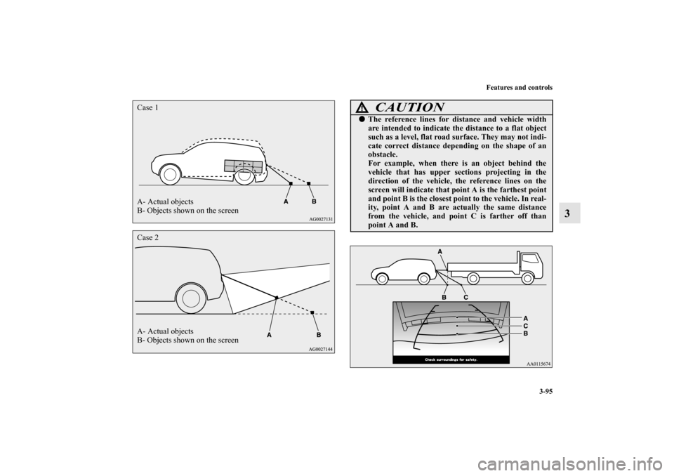
A- Actual objects
B- Objects shown on the screen Case 1Case 2
A- Actual objects
B- Objects shown on the screen
CAUTION
!�The reference lines for distance and vehicle width
are intended to indicate the distance to a flat object
such as a level, flat road surface. They may not indi-
cate correct distance depending on the shape of an
obstacle.
For example, when there is an object behind the
vehicle that has upper sections projecting in the
direction of the vehicle, the reference lines on the
screen will indicate that point A is the farthest point
and point B is the closest point to the vehicle. In real-
ity, point A and B are actually the same distance
from the vehicle, and point C is farther off than
point A and B.
BK0162600US.book 95 ページ 2013年3月22日 金曜日 午後2時41分
Page 350 of 460

6-10 For emergencies
6
How to use the tire repair kit
N00800600017
WA R N I N G
!�Never use the tire repair kit under in any of the situ-
ations listed below. The tire cannot be repaired by
the tire repair kit. If any of these situations occurs,
please contact an authorized Mitsubishi Motors
dealer or a repair facility of your choice.
• More than one tire is punctured.
• The puncture hole has a length or width of 1/7 inch
(4 mm) or greater.
• The tire is punctured in the side wall (A), not in the
tread (B).
• The vehicle has been driven with the tire almost
completely flat.
• The tire has completely slipped over the wheel rim
and come off the wheel.
• The wheel is damaged.
• A bump, cut or crack is on the tire.
• The tire sealant’s expiration date has passed. (The
expiration date is shown on the bottle label (C).)
• The ambient temperature is below -40 °F (-40 °C)
or above 140 °F (60 °C).
WA R N I N G
!�The tire sealant can cause health damage if swal-
lowed. If you accidentally swallow it, drink as much
water as possible and immediately seek medical
attention.�If the tire sealant gets in your eyes or on your skin,
rinse it away with lots of water. If you still sense an
abnormality, seek medical attention.�Consult a doctor immediately if any allergic reac-
tions occur.�Do not allow children to touch the tire sealant.
BK0162600US.book 10 ページ 2013年3月22日 金曜日 午後2時41分
Page 394 of 460

7-20 Vehicle care and maintenance
7
�Intended outboard sidewall:
• The sidewall that contains a whitewall, bears white let-
tering or bears manufacturer, brand, and/or model name
molding that is higher or deeper than the same molding
on the other sidewall of the tire, or
• The outward facing sidewall of an asymmetrical tire that
has a particular side that must always face outward
when mounted on a vehicle.
�Passenger car tire: a tire intended for use on passenger
cars, multipurpose passenger vehicles, and trucks that
have a gross vehicle weight rating (GVWR) of 10,000
pounds or less.
�Light truck (LT) tire: a tire designated by its manufacturer
as primarily intended for use on lightweight trucks or mul-
tipurpose passenger vehicles.
�Tread: portion of a tire that comes into contact with the
road.
�Tread rib: a tread section running circumferentially
around a tire.
�Tread separation: pulling away of the tread from the tire
carcass.
�Carcass: the tire structure, except tread and sidewall rub-
ber which, when inflated, bears the load.
�Sidewall: portion of a tire between the tread and bead.
�Section width: the linear distance between the exteriors of
the sidewalls of an inflated tire, excluding elevations due
to labeling, decoration, or protective bands.
�Bead: the part of the tire that is made of steel wires,
wrapped or reinforced by ply cords and that is shaped to
fit the rim.
�Ply: a layer of rubber-coated parallel cords.
�Cord: the strands forming the plies in the tire.�Rim: a metal support for a tire or a tire and tube assembly
upon which the tire beads are seated.
�Rim diameter: nominal diameter of the bead seat.
�Groove: the space between two adjacent tread ribs.
Tire Markings
BK0162600US.book 20 ページ 2013年3月22日 金曜日 午後2時41分
Page 395 of 460

Vehicle care and maintenance
7-21
7
Size Designation
EXAMPLE: P215/65R15
NOTE�
European/Japanese metric tire sizing is based on
European/Japanese design standards. Tires designed
to these standards have the tire size molded into the
sidewall beginning with the section width. The letter
“P” is absent from this tire size designation. Exam-
ple: 215/65R15 96H.
�LT (Light Truck) -metric tire sizing is based on
U.S.A. design standards. The size designation for
LT-metric tires is the same as for P-metric tires
except for the letters “LT” that are molded into the
sidewall preceding the size designation. Example:
LT235/85R16.
�
Temporary spare tires are high pressure compact
spares designed for temporary emergency use only.
Tires designed to this standard have the letter “T”
molded into the sidewall preceding the size designa-
tion. Example: T145/80D18 103M.Service Description
EXAMPLE: 95H
Maximum Load
Maximum load indicates the maximum load this tire is
designed to carry.
Maximum Pressure
Maximum Pressure indicates the maximum permissible
cold tire inflation pressure for this tire. PPassenger car tire size based on U.S.A. design
standards
215 Section width in millimeters (mm)
65Aspect ratio in percent (%)
Ratio of section height to section width of tire.
RConstruction code
• “R” means radial construction.
• “D” means diagonal or bias construction.
15 Rim diameter in inches (in)95Load index
A numerical code associated with the maxi-
mum load a tire can carry.
HSpeed symbol
A symbol indicating the range of speeds at
which a tire can carry a load corresponding to
its load index under certain operating condi-
tions.
The maximum speed corresponding to the
speed symbol should only be achieved under
specified operating conditions. (i.e. tire pres-
sure, vehicle loading, road conditions and
posted speed limits)
WA R N I N G
!�
Overloading of your tire is dangerous. Over-
loading can cause tire failure, affect vehicle
handling, and increase your stopping distance.
Use tires of the recommended load capacity for
your vehicle. Never overload them.
BK0162600US.book 21 ページ 2013年3月22日 金曜日 午後2時41分
Page 447 of 460
Specifications
9-5
9
Certification label
N01148200242
The certification label is located on the driver’s door sill.
Vehicle dimensions
N01147500541
Overall length 148.8 in (3,780 mm)Overall width 65.6 in (1,665 mm)Overall height 59.1 in (1,500 mm)Wheel base 96.5 in (2,450 mm)
BK0162600US.book 5 ページ 2013年3月22日 金曜日 午後2時41分
Overall width 65")