Page 278 of 460
5-6 Comfort controls
5Heater without air conditioning function
(if
so equipped)
N00737700031
The heater can only be used while the engine is running.Control panel
N00737800032
Blower speed selection dial
N00737900033
When the ignition switch is in the “ON” position, select the
blower speed by turning the blower speed selection dial.
Turning the dial clockwise will increase the blower speed;
turning the dial counterclockwise will decrease it. When the
dial is set to the “OFF” position, all fan-driven airflow will
stop.
1- Temperature control lever
2- Air selection lever
3- Mode selection dial
4- Electric rear window defogger switch → P. 3 - 1 2 5
5- Blower speed selection dial
BK0162600US.book 6 ページ 2013年3月22日 金曜日 午後2時41分
Page 284 of 460
5-12 Comfort controls
5
Temperature control lever
N00736600248
The temperature control lever is used to select the desired air
temperature.NOTE�While the engine coolant temperature is low, the tempera-
ture of the air from the heater will be cool/cold until the
engine warms up, even if you have selected warm air with
the lever.
Mode selection dial
N00736700223
To change the amount of air flowing from the vents, turn the
mode selection dial. Refer to “Changing the mode selection”
on page 5-3.
1- Cooler
2- Warmer
BK0162600US.book 12 ページ 2013年3月22日 金曜日 午後2時41分
Page 291 of 460

Comfort controls
5-19
5
Temperature control switch
N00737000324
Press or of the temperature control switch to the
desired temperature.
The selected temperature will be shown in the display (A).
NOTE�While the engine coolant temperature is low, the tempera-
ture of the air from the heater will be cool/cold until the
engine warms up, even if you have selected warm air with
the switch.
To prevent the windshield and windows from fogging up,
the vent mode will be changed to “ ” and the blower
speed will be reduced.
�When the temperature is set to the highest or the lowest
setting under the AUTO operation, the air selection and
the air conditioning will be automatically changed as fol-
lows.
• Quick Heating (When the temperature is set to the high-
est setting)
Outside air will be introduced and the air conditioning
will stop.
If the air selection and the air conditioning are operated
manually after an automatic changeover, manual opera-
tion will be selected.
• Quick Cooling (When the temperature is set to the low-
est setting)
Inside air will be recirculated and the air conditioning
will operate.
The above indicates the factory settings. You can personalize
the air selection switch and air conditioning switch to match
your personal preferences.
Contact your Mitsubishi Motors dealer or a repair facility of
your choice for assistance.
Refer to “Personalizing the air conditioning switch (Changing
the function setting)” on page5-24.
BK0162600US.book 19 ページ 2013年3月22日 金曜日 午後2時41分
Page 335 of 460

Comfort controls
5-63
5
�In the following circumstances, moisture can form on
compact discs and inside the audio system, preventing
normal operation.
• When there is high humidity (for example, when it is
raining).
• When the temperature suddenly rises, such as right after
the heater is turned on in cold weather.
In this case, wait until the moisture has had time to dry
out.
�When the CD player is subjected to violent vibrations,
such as during off-road driving, the tracking may not
work.
�When storing compact discs, always store them in their
separate cases. Never place compact discs in direct sun-
light, or in any place where the temperature or humidity is
high.
�Never touch the flat surface of the disc where there isn’t a
label. This will damage the disc surface and could affect
the sound quality. When handling a compact disc, always
hold it by the outer edge and the center hole.
�To clean a disc, use a soft, clean, dry cloth. Wipe directly
from the center hole toward the outer edge. Do not wipe in
a circle. Never use any chemicals such as benzine, paint
thinner, a disc spray cleaner, or an anti-static agent on the
disc.
�Do not use a ball point pen, felt pen, pencil, etc. to write
on the label surface of the disc. �Do not put additional labels or stickers on compact discs.
Also, do not use any compact disc on which a label or
sticker has started to peel off or any compact disc that has
stickiness or other contamination left by a peeled-off label
or sticker. If you use such a compact disc, the CD player
may stop working properly and you may not be able to
eject the compact disc.
BK0162600US.book 63 ページ 2013年3月22日 金曜日 午後2時41分
Page 343 of 460
For emergencies
6-3
6
3. You could be injured if the vehicles move. Set the parking
brake firmly on each vehicle. Put an automatic transaxle
or CVT in “P” (PARK) or a manual transaxle in “N”
(Neutral).
4. Turn the ignition switch to the “OFF” position or put the
operation mode in OFF.NOTE�Turn off all lights, heater, and other electrical loads. This
will avoid sparks and help save both batteries.
5. Make sure your battery electrolyte is at the proper level.
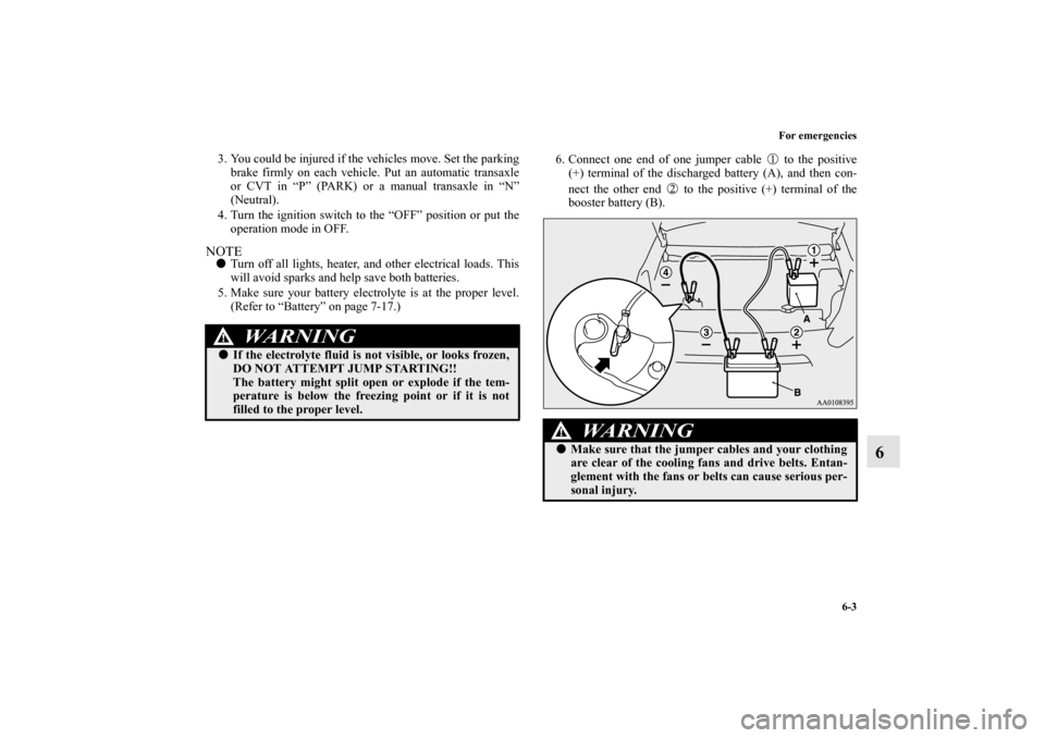
(Refer to “Battery” on page 7-17.)6. Connect one end of one jumper cable to the positive
(+) terminal of the discharged battery (A), and then con-
nect the other end to the positive (+) terminal of the
booster battery (B).
WA R N I N G
!�If the electrolyte fluid is not visible, or looks frozen,
DO NOT ATTEMPT JUMP STARTING!!
The battery might split open or explode if the tem-
perature is below the freezing point or if it is not
filled to the proper level.
WA R N I N G
!�Make sure that the jumper cables and your clothing
are clear of the cooling fans and drive belts. Entan-
glement with the fans or belts can cause serious per-
sonal injury.
BK0162600US.book 3 ページ 2013年3月22日 金曜日 午後2時41分
Page 412 of 460
7-38 Vehicle care and maintenance
7
�Some fuses may not be installed on your vehicle, depend-
ing on the vehicle model or specifications.
�The table above shows the main equipment corresponding
to each fuse.
Engine compartment fuse location table
10 Control unit 7.5 A
11 Rear fog light 10 A
12 Door lock 15 A
13 Interior light (Dome light) 15 A
14 Rear window wiper 15 A
15 Gauges 7.5 A
16 Relay 7.5 A
17 Heated seats 20 A
18 Option 10 A
19 Heated outside rearview mirrors 7.5 A
20 Windshield wiper 20 A
21 Back-up light 7.5 A
22 Defogger 30 A
23 Heater 30 A
24 — — —
25 Radio 10 A
26 Electronic controlled unit 15 ANo.
Symbol
Electrical system
Capacity
No.
Symbol
Electrical system
Capacity
SBF1 Radiator fan motor 40 A*
SBF2 Anti-lock braking system 30 A*
SBF3 Ignition switch 40 A*
SBF4 Power window control 40 A*
BF1 DC-DC (P/T) 30 ATy p e A
BK0162600US.book 38 ページ 2013年3月22日 金曜日 午後2時41分
Page 414 of 460
7-40 Vehicle care and maintenance
7
*: Fusible link
�Some fuses may not be installed on your vehicle, depend-
ing on the vehicle model or specifications.
�The table above shows the main equipment corresponding
to each fuse.The fuse block does not contain spare 7.5 A, 10 A or 15 A
fuses. If one of these fuses burns out, substitute with the fol-
lowing fuse.
7.5 A: Outside rearview mirrors
10 A: Option
15 A: Cigarette lighter
When using a substitute fuse, replace with a fuse of the correct
capacity as soon as possible.
Identification of fuse
No.
Symbol
Electrical system
Capacity
SBF1 PTC heater 40 A*
SBF2 PTC heater 40 A*
SBF3 PTC heater 40 A*Ty p e B
Capacity
Color
7.5 A Brown
10 A Red
15 A Blue
20 A Yellow
30 A Green (fuse type) /Pink (fusible link type)
40 A Green (fusible link type)
BK0162600US.book 40 ページ 2013年3月22日 金曜日 午後2時41分
Page 455 of 460

Alphabetical index
3
F
Floor mat 4-3
Fluid
Brake fluid 9-9
Continuously variable transmission (CVT) fluid 7-15
,9-9
Engine coolant 7-11
,9-9
Manual transaxle 9-9
Washer fluid 7-15
,9-9
Fluid capacities and lubricants 9-9
Free-hand advanced security transmitter (F.A.S.T.-key) 3-13
Front fog lights
Bulb capacity 7-44
Indicators 3-110
Replacement 7-50
Switch 3-120
Front seat adjustment 2-3
Front side-marker lights
Bulb capacity 7-44
Replacement 7-47
Front turn signal light
Bulb capacity 7-44
Replacement 7-48
Fuel
Filling the fuel tank 1-4
Fuel economy 4-2
Fuel hoses 7-31
Fuel remaining warning display 3-103
Fuel selection 1-2Tank capacity 9-9
Fuel remaining display 3-102
Fuses 7-36
Fusible links 7-35
G
General maintenance
Maintenance 7-33
General vehicle data 9-5
Genuine parts 1-9
Glove compartment 3-165
H
Hazard warning flasher switch 3-119
Hazard warning lights 3-110
Head restraints 2-11
Headlights
Bulb capacity 7-44
Dimmer 3-117
Headlight flasher 3-118
Switch 3-114
Heater without air conditioning function 5-6
High beam indicator 3-110
High coolant temperature warning light 3-113
High-mounted stop light
Bulb capacity 7-44
Hill start assist 3-69
Hood lock release mechanism and safety catch 7-34
Hook
BK0162600US.book 3 ページ 2013年3月22日 金曜日 午後2時41分


