2014 MITSUBISHI LANCER SPORTBACK weight
[x] Cancel search: weightPage 172 of 422
Rear-view camera (if so equipped)
Features and controls 5-105
5
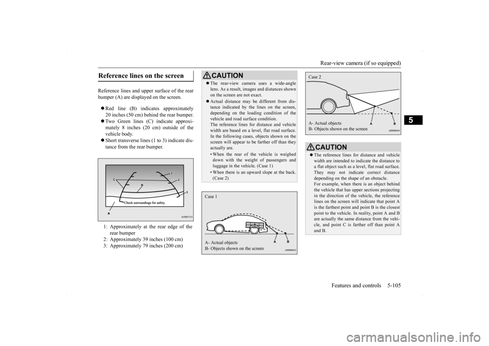
Reference lines and upper surface of the rear bumper (A) are displayed on the screen. Red line (B) indicates approximately 20 inches (50 cm) behind the rear bumper. Two Green lines (C) indicate approxi- mately 8 inches (20 cm) outside of thevehicle body. Short transverse lines (1 to 3) indicate dis- tance from the rear bumper.
Reference lines on the screen
1: Approximately at the rear edge of the
rear bumper
2: Approximately 39 inches (100 cm) 3: Approximately 79 inches (200 cm)
CAUTION The rear-view camera uses a wide-angle lens. As a result, images and distances shown on the screen are not exact. Actual distance may be different from dis- tance indicated by the lines on the screen, depending on the loading condition of the vehicle and road surface condition.The reference lines for distance and vehicle width are based on a level, flat road surface. In the following cases, objects shown on thescreen will appear to be farther off than they actually are.• When the rear of the vehicle is weigheddown with the weight of passengers and luggage in the vehicle. (Case 1)• When there is an upward slope at the back.(Case 2)
Case 1 A- Actual objects B- Objects shown on the screen
CAUTION The reference lines for distance and vehicle width are intended to indicate the distance to a flat object such as a level, flat road surface.They may not indicate correct distance depending on the shape of an obstacle. For example, when there is an object behindthe vehicle that has upper sections projecting in the direction of the vehicle, the reference lines on the screen will indicate that point Ais the farthest point a
nd point B is the closest
point to the vehicle. In reality, point A and B are actually the same distance from the vehi-cle, and point C is farther off than point A and B.Case 2 A- Actual objects B- Objects shown on the screen
BK0200700US.book
105 ページ 2013年2月15日 金曜日 午後12時17分
Page 265 of 422
Parking 6-6 Driving safety
6
N00629600261
When parking on a hill, set the parking brake, and turn the front wheels toward the curb on adownhill, or away from the curb on an uphill. If necessary, apply chocks to wheels. Place the gearshift lever into the “R” (Reverse) position when parking on a down-hill slope, into the 1s
t position when parking
on an uphill slope. Be sure that the parking brake is firmly set when parked and that the selector lever(CVT) or gearshift lever (Twin Clutch SST) is in the “P” (PARK) position. When parking on a hill, it is important to setthe parking brake before moving the selector lever (CVT) or gearshift lever (Twin Clutch
SST) to the “P” (PARK) position. This pre- vents loading the parking brake against the transaxle. When this happens, it is difficult to move the selector lever (CVT) or gearshiftlever (Twin Clutch SST) out of the “P” (PARK) position. Never leave the engi
ne running while you
take a short sleep/rest. Also, never leave the engine running in a closed or poorly venti-lated place. Your front bumper can be damaged if you scrape it over curbs or parking stop blocks. Be careful when traveling up or down steepslopes where your bumper can scrape the road.
When leaving the vehicle unattended, always carry the key and lock all doors and the rear hatch.Always try to park your vehicle in a well lit area.
N00629900323
It is very important to know how muchweight your vehicle can carry. This weight is called the vehicle capacity weight andincludes the weight of all occupants, cargo and non-factory-installed options. The tire and loading information placard located onthe driver’s door sill of your vehicle will show how much weight it may properly carry.
Parking Parking on a hill For vehicles equipped with man- ual transaxle For vehicles equipped with contin- uously variable transmission (CVT) or Twin Clutch SST
Parking with the engine run- ning
WA R N I N G Leaving the engine running risks injury or death from accidentally moving the gear- shift lever (manual transaxle or Twin Clutch SST) or the selector lever (CVT) orfrom the accumulation of toxic exhaust fumes in the passenger compartment.
Where you park
WA R N I N G Do not park your vehicle in areas where combustible materials such as dry grass or leaves can come in contact with a hot exhaust, since a fire could occur.
When leaving the vehicle Loading information
BK0200700US.bo
ok 6 ページ 2013年2月15日 金曜日 午後12時17分
Page 266 of 422
Loading information Driving safety 6-7
6
It is important to fami
liarize yourself with the
following terms before loading your vehicle: Vehicle maximum load on the tire: load on an individual tire that is determined by distributing to each axle its share of the maximum loaded vehicle weight anddividing by two. Vehicle normal load on the tire: load on an individual tire that is determined by dis-tributing to each axle its share of the curb weight, accessory weight, and normal occupant weight and dividing by two. Maximum loaded vehicle weight: the sum of - (a) Curb weight;(b) Accessory weight; (c) Vehicle capacity weight; and (d) Production options weight. Curb weight: the weight of a motor vehi- cle with standard equipment including the maximum capacity of fuel, oil, and cool-ant.
Accessory weight: the combined weight (in excess of those standard items which may be replaced) of automatic transmis- sion, power steering, power brakes, powerwindows, power seats, radio, and heater, to the extent that these items are available as factory- installed equipment (whetherinstalled or not). Vehicle capacity weight: the rated cargo and luggage load plus 150 lbs (68 kg)
*
times the vehicle’s designated seatingcapacity. Production options weight: the combined weight of those installed regular produc-tion options weighing over 5 lbs (2.3 kg) in excess of those standard items which they replace, not previously considered incurb weight or accessory weight, includ- ing heavy duty brakes, ride levelers, roof rack, heavy duty battery, and special trim. Normal occupant weight: 150 lbs (68 kg)
*
times the number of specified occupants. (In your vehicle the number is 3) Occupant distribution: distribution of occupants in a vehicle as specified. (In your vehicle the distribution is 2 in front,1 in second row seat)
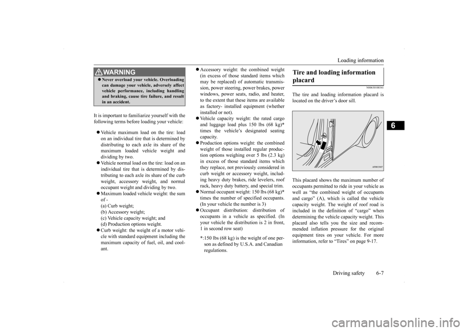
N00630100341
The tire and loading information placard islocated on the driver’s door sill. This placard shows the maximum number of occupants permitted to ride in your vehicle aswell as “the combined weight of occupants and cargo” (A), which is called the vehicle capacity weight. The weight of roof road isincluded in the definition of “cargo” when determining the vehicle capacity weight. This placard also tells you the size and recom-mended inflation pressure for the original equipment tires on your vehicle. For more information, refer to “Tires” on page 9-17.
WA R N I N G Never overload your vehicle. Overloading can damage your vehicle, adversely affect vehicle performance, including handling and braking, cause tire failure, and result in an accident.
* :150 lbs (68 kg) is th
e weight of one per-
son as defined by U.S.A. and Canadian regulations.
Tire and loading information placard
BK0200700US.bo
ok 7 ページ 2013年2月15日 金曜日 午後12時17分
Page 267 of 422
Loading information 6-8 Driving safety
6
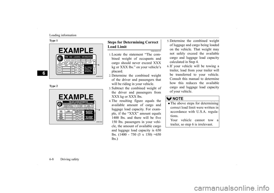
Ty p e 1 Ty p e 2
N00630201235
1.Locate the statement “The com- bined weight of occupants andcargo should never exceed XXX kg or XXX lbs.” on your vehicle’s placard.2.Determine the combined weight of the driver and passengers that will be riding in your vehicle.3.Subtract the combined weight of the driver and passengers from XXX kg or XXX lbs.4.The resulting figure equals the available amount of cargo and luggage load capacity. For exam-ple, if the “XXX” amount equals 1400 lbs. and there will be five 150 lbs. passengers in your vehi-cle, the amount of available cargo and luggage load capacity is 650 lbs. (1400 - 750 (5 x 150) =650 lbs.)
5.Determine the combined weightof luggage and cargo being loaded on the vehicle. That weight may not safely exceed the available cargo and luggage load capacitycalculated in Step 4.6.If your vehicle will be towing atrailer, load from your trailer willbe transferred to your vehicle. Consult this manual to determine how this reduces the availablecargo and luggage load capacity of your vehicle.
Steps for Determining Correct Load Limit
NOTE
The above steps for determining correct load limit were written in accordance with U.S.A. regula-tions. Your vehicle cannot tow a trailer, so step 6 is irrelevant.
BK0200700US.bo
ok 8 ページ 2013年2月15日 金曜日 午後12時17分
Page 268 of 422
Loading information Driving safety 6-9
6
NOTE
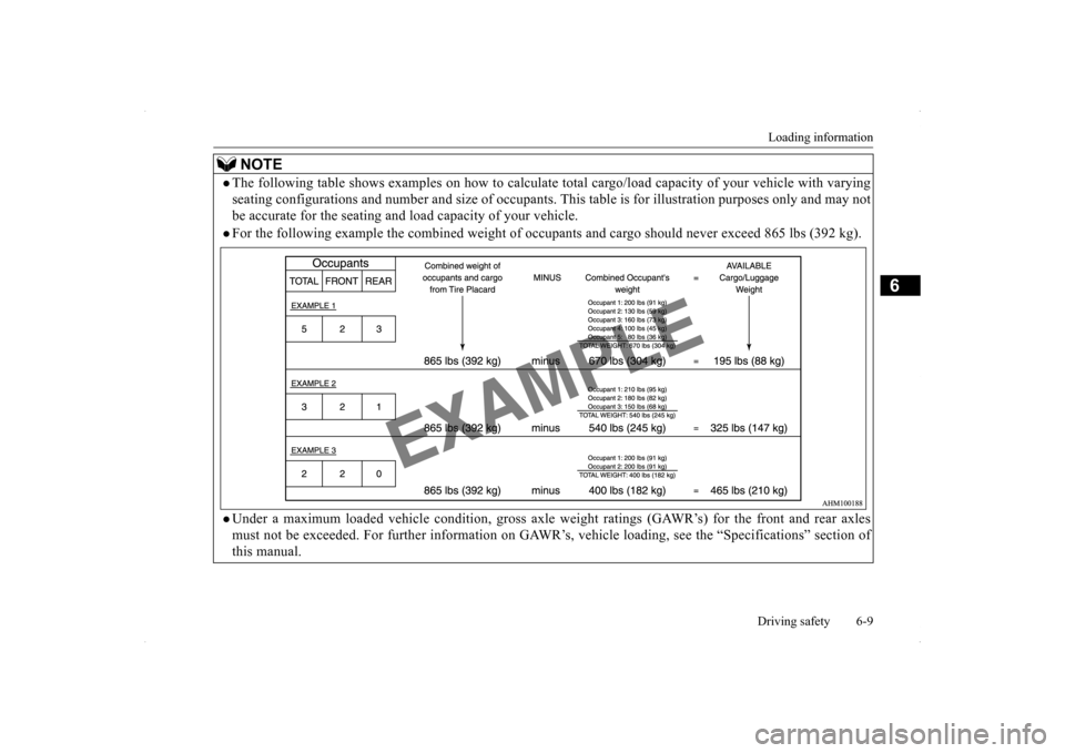
The following table shows examples on how to calculate to
tal cargo/load capacity of your vehicle with varying
seating configurations and number and size of occupants.
This table is for illustration purposes only and may not
be accurate for the seating and lo
ad capacity of your vehicle.
For the following example the combined weight of oc
cupants and cargo should never exceed 865 lbs (392 kg).
Under a maximum loaded vehicle condition, gross axle
weight ratings (GAWR’s) for the front and rear axles
must not be exceeded. For further information on GAWR
’s, vehicle loading, see the “Specifications” section of
this manual.
BK0200700US.bo
ok 9 ページ 2013年2月15日 金曜日 午後12時17分
Page 269 of 422
Cargo loads 6-10 Driving safety
6
N00629700493
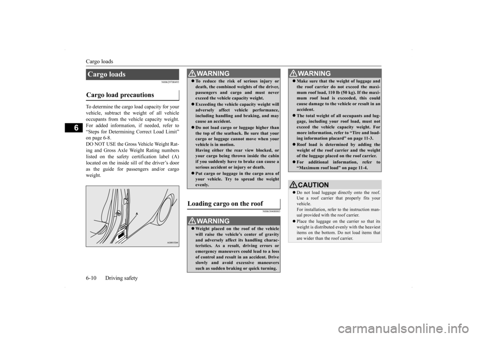
To determine the cargo load capacity for your vehicle, subtract the weight of all vehicle occupants from the vehicle capacity weight.For added information, if needed, refer to “Steps for Determining Correct Load Limit” on page 6-8.DO NOT USE the Gross Vehicle Weight Rat-ing and Gross Axle Weight Rating numbers listed on the safety certification label (A) located on the inside sill of the driver’s dooras the guide for passengers and/or cargo weight.
N00630400083
Cargo loads Cargo load precautions
WA R N I N G To reduce the risk of serious injury or death, the combined weights of the driver, passengers and cargo and must never exceed the vehicle capacity weight. Exceeding the vehicle capacity weight will adversely affect vehicle performance, including handling and braking, and maycause an accident. Do not load cargo or luggage higher than the top of the seatback. Be sure that your cargo or luggage cannot move when your vehicle is in motion.Having either the rear view blocked, or your cargo being thrown inside the cabin if you suddenly have to brake can cause aserious accident or injury or death. Put cargo or luggage in the cargo area of your vehicle. Try to spread the weight evenly.
Loading cargo on the roof
WA R N I N G Weight placed on the roof of the vehicle will raise the vehicle’s center of gravity and adversely affect its handling charac-teristics. As a result, driving errors or emergency maneuvers could lead to a loss of control and result in an accident. Driveslowly and avoid excessive maneuvers such as sudden braking or quick turning.
Make sure that the weight of luggage and the roof carrier do not exceed the maxi- mum roof load, 110 lb (50 kg). If the maxi- mum roof load is exceeded, this could cause damage to the ve
hicle or result in an
accident. The total weight of all occupants and lug- gage, including your roof load, must not exceed the vehicle capacity weight. For more information, refer to “Tire and load-ing information placard” on page 11-3. Roof load is determined by adding the weight of the roof carrier and the weight of the luggage placed on the roof carrier. For additional information, refer to “Maximum roof load” on page 11-4.CAUTION Do not load luggage directly onto the roof. Use a roof carrier th
at properly fits your
vehicle. For installation, refer to the instruction man- ual provided with the roof carrier. Place the luggage on the carrier so that its weight is distributed evenly with the heaviest items on the bottom. Do not load items that are wider than the roof carrier.WA R N I N G
BK0200700US.bo
ok 10 ページ 2013年2月15日 金曜日 午後12時17分
Page 340 of 422
How to change a tire
For emergencies 8-7
8
6. Get the jack, bar and wheel nut wrench ready.Refer to “Tools and jack” on page 8-5.
N00849600302
The compact spare tire is designed to savespace in the luggage compartment. Its lighter weight makes it easier to use if a flat tire occurs.
N00849701313
1. Lift up the board.
WA R N I N G Be sure to apply chocks or blocks to the correct tire when jacking up the vehicle. If the vehicle moves while jacked up, the jack could slip out of position, leading to an accident.NOTE
The chocks shown in the illustration do not come with your vehicle. It is recommended that you purchase chocks or blocks and keepthem in the vehicle for use if needed. If chocks or blocks are not available, use stones or any other objects that are large enough to hold the wheel in position.
Spare tire information Compact spare tire
WA R N I N G Tires, including spare tire, degrade over time with age even when they are not being used. It is recommended that tires over 6 years generally be replaced even if damage is not obvious.CAUTION While the compact spare tire is stowed, the inflation pressure should be checked at least once a month to assure that it remains at therecommended inflation pressure. See the tire and loading information placard attached to the driver’s door sill.Refer to “Tire and loading information plac- ard” on page 11-3. Driving with an improperly inflated tire can cause an accident. If you have no choice but to drive with an under-inflated tire, keepyour speed down and avoid sudden steering or braking, if possible
. Inflate the tire to the
correct pressure as soon as possible. Refer to“Tire inflation pressures” on page 9-21. The compact spare tire should be used only temporarily. While the compact spare tire is being used, the tire pressure monitoring sys- tem will not function properly. Have the tire replaced or repaired at an authorized Mit- subishi Motors dealer or a repair facility ofyour choice as soon as possible. You can use the same wheel nuts on the com- pact spare tire wheel.
Do not go over 50 mph (80 km/h) when driv- ing with the compact spare tire. Avoid fast starting and braking when driving with the compact spare tire. Do not drive through automatic car washes and over obstacles that could possibly dam-age the underside of your vehicle. Because the compact spare tire is smaller than the original tire, there is less clearance betweenthe ground and your vehicle. Because the compact spare tire is designed only for your vehicle, do not use it on any other vehicle. Do not put the compact spare tire on a differ- ent wheel, and do not put standard tires, snow tires, wheel covers or trim rings on thecompact spare wheel. Otherwise, you could damage these parts or other parts on your vehicle. Do not use snow chain with your compact spare tire. Using a chain could cause damageto your vehicle and loss of the chains.
To remove the compact spare tire
CAUTION
BK0200700US.bo
ok 7 ページ 2013年2月15日 金曜日 午後12時17分
Page 354 of 422
View of the engine compartment
Vehicle care and maintenance 9-5
9
Unlatch the prop from the engine hood and put it back in its retainer. Slowly lower the engine hood about 8 inches (20 cm), then let it drop from its own weight.
N00937600670
N00937701968
It is normal for an engi
ne to use oil. You may
need to add oil between the recommended oil
To close
CAUTION Be careful not to trap your hands or fingers when closing the engine hood. Make sure the engine hood is firmly closed before driving. If you drive without the engine hood com-pletely closed, it could open up while driv- ing.NOTE
If this does not close the engine hood prop- erly, drop it again from a slightly higher position.
Do not push down strongly on the engine hood. Depending on how strongly or where you push down, you could create a dent in the vehicle body. If you drive with the engine hood left open, warning display is displayed on the informa- tion screen in the multi-information display.
Type 1 Type 2View of the engine compart- ment
NOTE
Except for vehicles with turbocharger
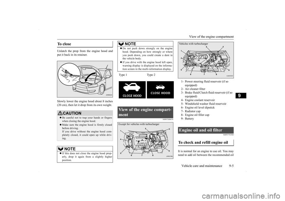
1- Power steering fluid reservoir (if so
equipped)
2- Air cleaner filter 3- Brake fluid/Clutch fluid reservoir (if so
equipped)
4- Engine coolant reservoir 5- Windshield washer fluid reservoir6- Engine oil level dipstick7- Radiator cap 8- Engine oil filler cap 9- Battery Engine oil and oil filter To check and refill engine oil Vehicles with turbocharger
BK0200700US.bo
ok 5 ページ 2013年2月15日 金曜日 午後12時17分