2014 MINI Paceman steering wheel
[x] Cancel search: steering wheelPage 79 of 218

Do not continue driving without run-flat
tires
Do not continue driving if the vehicle is not
equipped with run-flat tires; continued driving
may result in serious accidents. ◀
When a low inflation pressure is indicated, DSC
Dynamic Stability Control is switched on if nec‐
essary.
Actions in the event of a flat tire Normal tires1.Identify the damaged tire.
Do this by checking the air pressure in all
four tires. The tire pressure gauge of the
Mobility System, refer to page 161, can be
used for this purpose.
If the tire inflation pressure in all four tires is
correct, the Tire Pressure Monitor may not
have been reset. Reset the system.
If an identification is not possible, please
contact the service center.2.Rectify the flat tire using the Mobility Sys‐
tem, refer to page 161.
Use of tire sealant, e.g., the Mobility Sys‐
tem, may damage the TPM wheel electron‐
ics. In this case, have the electronics
checked at the next opportunity and have
them replaced if necessary.
Run-flat tires
You can continue driving with a damaged tire
at speeds up to 50 mph/80 km/h.
Do not continue driving without run-flat
tires
Do not continue driving if the vehicle is not
equipped with run-flat tires; continued driving
may result in serious accidents. ◀
Continued driving with a flat tire
If continuing to drive with a damaged tire:1.Avoid sudden braking and steering maneu‐
vers.2.Do not exceed a speed of 50 mph/80 km/h.3.Check the air pressure in all four tires at the
next opportunity.
If the tire inflation pressure in all four tires is
correct, the Tire Pressure Monitor may not
have been reset. Reset the system.
Possible driving distance with complete loss of
tire inflation pressure:
The possible driving distance after a loss of tire
inflation pressure depends on the cargo load
and the driving style and conditions.
For a vehicle containing an average load, the
possible driving distance is ap‐
prox. 50 miles/80 km.
When the vehicle is driven with a damaged tire,
its handling characteristics change, e.g., re‐
duced lane stability during braking, a longer
braking distance, and altered self-steering
properties. Adjust your driving style accord‐
ingly. Avoid abrupt steering maneuvers or driv‐
ing over obstacles, e. g., curbs, potholes, etc.
Because the possible driving distance depends
on how the vehicle is used during the trip, the
actual distance may be smaller or greater de‐
pending on the driving speed, road conditions,
external temperature, cargo load, etc.
Continued driving with a flat tire
Drive moderately and do not exceed a
speed of 50 mph/80 km/h.
A loss of tire inflation pressure results in a
change in the handling characteristics, e.g., re‐
duced lane stability during braking, a longer
braking distance and altered self-steering prop‐
erties. ◀
Seite 79SafetyControls79
Online Edition for Part no. 01 40 2 911 521 - VI/13
Page 81 of 218

Driving stability control systemsVehicle equipment
This chapter describes all series equipment as
well as country-specific and special equipment
offered for this model series.Therefore, it also
describes equipment that may not be found in
your vehicle, for instance due to the selected
special equipment or the country version. This
also applies to safety-related functions and sys‐
tems.
Antilock Brake System
ABS
ABS prevents locking of the wheels duringbraking.
Steerability is maintained even during full brak‐
ing. This increases active driving safety.
ABS is operational every time you start the en‐
gine.
Electronic brake-force distribution EBVThe system controls the brake pressure in the
rear wheels to ensure stable braking behavior.
CBC Cornering Brake Control
When braking in curves or during a lane
change, driving stability and steering response
are improved further.
Brake assistant When the brakes are applied rapidly, this sys‐
tem automatically produces the maximum
braking force boost. In this way, the system
helps keep the braking distance as short as
possible. This system utilizes all of the benefits
provided by ABS.Do not reduce the pressure on the brake pedal
for the duration of full braking.
Dynamic Stability Con‐
trol DSC
The concept
DSC prevents traction loss in the driving wheels
when driving away and accelerating.
DSC also recognizes unstable vehicle condi‐
tions, such as fishtailing or nose-diving. Subject
to physical limits, DSC helps to keep the vehicle
on a steady course by reducing engine speed
and by applying brakes to the individual
wheels.
DSC is operational every time you start the en‐
gine.
Adjust your driving style to the situation
An appropriate driving style is always the
responsibility of the driver.
The laws of physics cannot be repealed, even
with DSC.
Do not reduce the additional safety margin
with a risky driving style, as otherwise there is a
risk of an accident. ◀
Deactivating DSC
Press the switch until the DSC OFF indicator
lamp lights up in the speedometer and DSC OFF
Seite 81Driving stability control systemsControls81
Online Edition for Part no. 01 40 2 911 521 - VI/13
Page 83 of 218

The indicator lamp in the speedometer
lights up and TRACTION appears in the
tachometer.
DTC is activated.
Hill drive-off assistant This system supports driving away on gradients.
The handbrake is not required.
1.Hold the vehicle in place with the foot
brake.2.Release the foot brake and drive away
without delay.
Driving off without delay
After releasing the foot brake, start driv‐
ing without delay, since the drive-off assistant
will not hold the vehicle in place for more than
approx. 2 seconds and the vehicle will begin
rolling back. ◀
ALL4 all-wheel system
ALL4 is the all-wheel system of your MINI. The
combined effects of ALL4 and DSC further opti‐
mize the traction and dynamic driving charac‐
teristics. The ALL4 all-wheel system variably
distributes the drive forces to the front and rear
axles depending on the driving situation and
prevailing road conditions.
Sport button
When this button is pressed, the vehicle re‐
sponds in an even sportier manner.▷The engine responds more spontaneously
to accelerator movements.▷The steering responds more directly.▷Cooper S, John Cooper Works: the engine
sounds sportier when coasting.▷For automatic transmissions: more rapid
gear changes in the Sport program.
Activating the system
Press the switch; the LED in the button lights up
and SPORT is displayed briefly in the tachome‐
ter.
Deactivating the system
▷Press the switch again.▷Switch the engine off.Seite 83Driving stability control systemsControls83
Online Edition for Part no. 01 40 2 911 521 - VI/13
Page 84 of 218

Driving comfortVehicle equipment
This chapter describes all series equipment as
well as country-specific and special equipment
offered for this model series.Therefore, it also
describes equipment that may not be found in
your vehicle, for instance due to the selected
special equipment or the country version. This
also applies to safety-related functions and sys‐
tems.
Cruise control The concept
The system is functional at speeds beginning at
approx. 20 mph/30 km/h.
The vehicle stores and maintains the speed
specified using the controls on the steering
wheel.
Do not use cruise control
Do not use the system if unfavorable con‐
ditions make it impossible to drive at a constant
speed, for instance:▷On curvy roads.▷In heavy traffic.▷On slippery roads, in fog, snow or rain, or
on a loose road surface.
Otherwise, you could lose control of the vehicle
and cause an accident. ◀
Controls
At a glance1Maintaining, storing, and increasing the
speed2Activating/deactivating cruise control3Maintaining, storing, and reducing the
speed4Resuming cruise control
Switching on
Press button 2.
The indicator lamp lights up in thespeedometer. Cruise control is ready to
operate and can be activated.
Switching off Press button 2.
▷When activated: press twice.▷When interrupted: press once.
The displays go out. The stored target speed is
cleared.
Interrupting Press button 2.
The system is interrupted automatically if
▷The brakes are applied.▷The clutch pedal is depressed.Seite 84ControlsDriving comfort84
Online Edition for Part no. 01 40 2 911 521 - VI/13
Page 140 of 218

▷Dial a stored phone number, such as from
the list of accepted calls.▷End the call.
When the ignition and the radio ready state are
switched off, such as after the remote control is
removed, an existing call can be continued for
up to 25 minutes on the hands-free system.
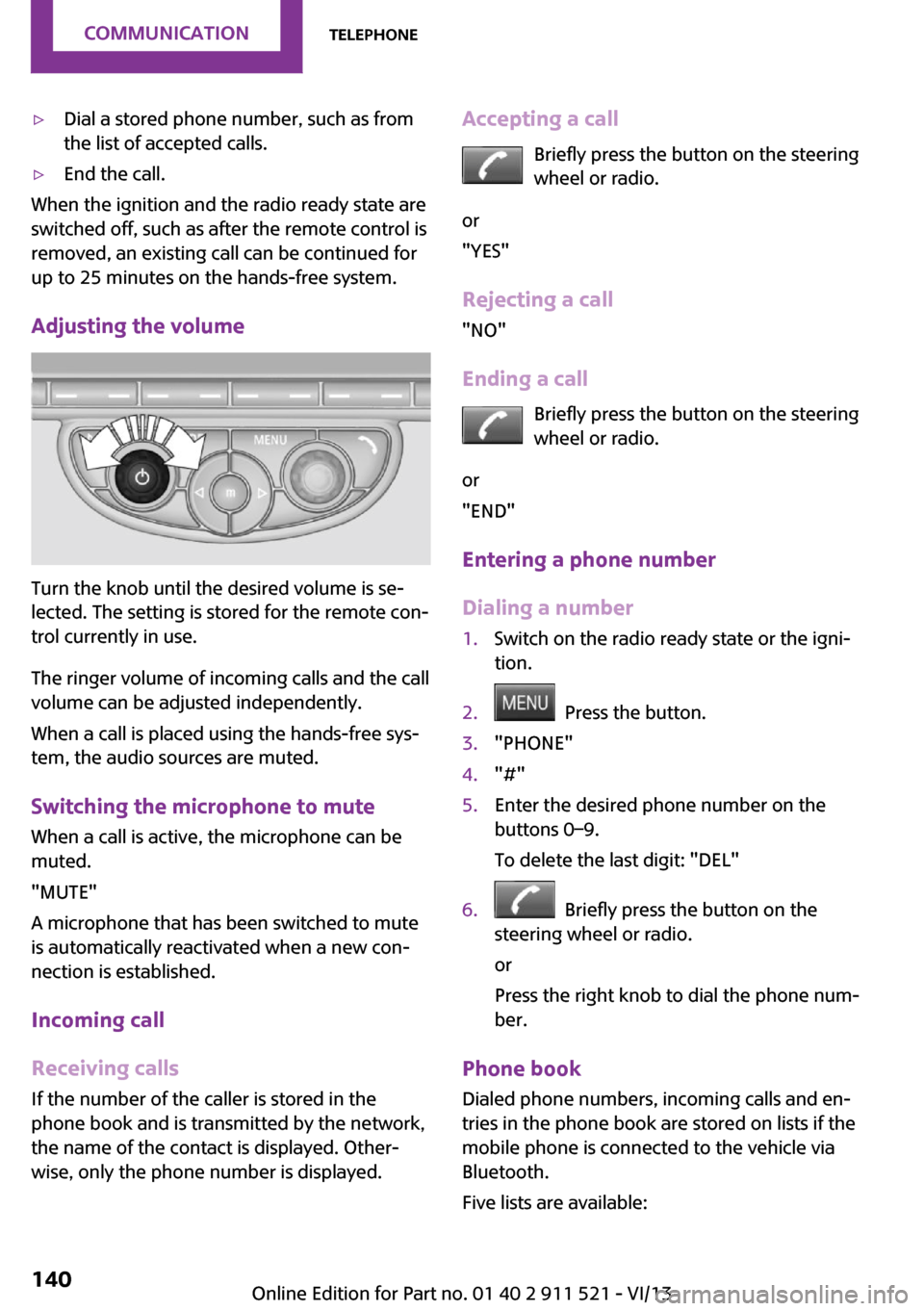
Adjusting the volume
Turn the knob until the desired volume is se‐
lected. The setting is stored for the remote con‐
trol currently in use.
The ringer volume of incoming calls and the call
volume can be adjusted independently.
When a call is placed using the hands-free sys‐
tem, the audio sources are muted.
Switching the microphone to mute
When a call is active, the microphone can be
muted.
"MUTE"
A microphone that has been switched to mute
is automatically reactivated when a new con‐
nection is established.
Incoming call
Receiving calls If the number of the caller is stored in the
phone book and is transmitted by the network,
the name of the contact is displayed. Other‐
wise, only the phone number is displayed.
Accepting a call
Briefly press the button on the steering
wheel or radio.
or
"YES"
Rejecting a call
"NO"
Ending a call Briefly press the button on the steering
wheel or radio.
or
"END"
Entering a phone number
Dialing a number1.Switch on the radio ready state or the igni‐
tion.2. Press the button.3."PHONE"4."#"5.Enter the desired phone number on the
buttons 0–9.
To delete the last digit: "DEL"6. Briefly press the button on the
steering wheel or radio.
or
Press the right knob to dial the phone num‐
ber.
Phone book
Dialed phone numbers, incoming calls and en‐
tries in the phone book are stored on lists if the
mobile phone is connected to the vehicle via
Bluetooth.
Five lists are available:
Seite 140CommunicationTelephone140
Online Edition for Part no. 01 40 2 911 521 - VI/13
Page 141 of 218

▷"A-Z"
Entries of the phone book of the SIM card
or of the mobile phone, which consist of a
name and phone number, are sorted in al‐
phabetical order.▷"TOP8"
The Top 8 list contains the eight phone
numbers that were dialed most frequently.▷"LAST8"
The last eight phone numbers that were di‐
aled are stored. The phone number dialed
last is at the top of the list.▷"CALLS"
The phone numbers of the last eight ac‐
cepted calls are stored. For this to be possi‐
ble, it must be possible to transmit the
phone number of the caller.▷"MISSED"
The phone numbers of the last eight calls
that were not accepted are stored. For this
to be possible, it must be possible to trans‐
mit the phone number of the caller.
Dialing a phone number from the phone
book
The list A-Z is available for phone book entries.
If entries with different names but the same
phone number are transferred to the vehicle
from the mobile phone, only one entry is dis‐
played.
The display of the phone book entries on the
radio may differ from the display on the mobile
phone, such as the order of the first and last
names.
1.Switch on the radio ready state or the igni‐
tion.2. Press the button.3."PHONE"4."A-Z"5. The arrows indicate that additional
letters can be displayed.Turn the right knob to display additional
letters if necessary.6.Turn the right knob to select the first letter
of the entry.7.Select the entry with the function button.
The phone number is dialed.
To display all entries:
1.Turn the right knob to select the first letter
of the entry and press the knob.2.Turn the right knob to select the desired
entry and press the knob.
or
Press the button on the steering
wheel or radio to dial the number.
The phone number is dialed.
Editing and dialing a phone number
from the phone book
You can edit the phone number of an entry be‐
fore making a call. This change is not stored in
the phone book.
1.Selecting an entry.2."EDIT"3.To delete a digit: "DEL"4.Enter additional digits on the buttons 0–9.5.Press the right knob to dial the phone num‐
ber.
Dialing a phone number from the phone
book using the buttons on the steering
wheel
1. Press and hold the button to dis‐
play the Telephone menu.2.Press the arrow buttons on the steering
wheel to leaf through the phone book.3. Press the button to dial the phone
number.
Seite 141TelephoneCommunication141
Online Edition for Part no. 01 40 2 911 521 - VI/13
Page 160 of 218

Maximum speed of winter tires
If the maximum speed of the vehicle is higher
than the permissible speed for the winter tires,
then display a corresponding sign in the field of
vision. You can obtain this sign from the tire
specialist or from your service center.
Maximum speed for winter tires
Do not exceed the maximum speed for
the winter tires; otherwise, tire damage and ac‐
cidents can occur. ◀
Run-flat tires When mounting new tires or changing fromsummer to winter tires or vice versa, use run-
flat tires for your own safety. Also, a compact
wheel is not available in case of a flat tire. Your
service center will be glad to advise you.
Rotating wheels between axles
Different wear patterns occur on the front and
rear axles, depending on the individual condi‐
tions of use.
To ensure even wear on the tires, the wheels
can be rotated between the axles. Your service
center will be glad to advise you.
After changing the tires, check the tire inflation
pressure and correct it if necessary.
Storage Store wheels and tires in a cool, dry place with
as little exposure to light as possible.
Always protect tires against all contact with oil,
grease and fuels.
Do not exceed the maximum tire inflation pres‐
sure indicated on the side wall of the tire.Run-flat tires
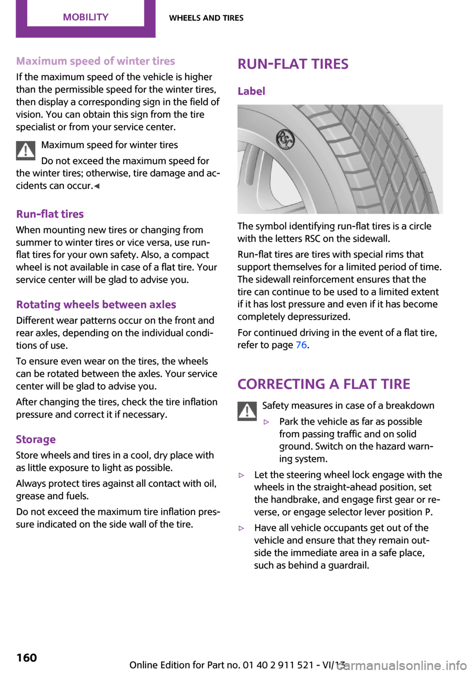
Label
The symbol identifying run-flat tires is a circle
with the letters RSC on the sidewall.
Run-flat tires are tires with special rims that
support themselves for a limited period of time.
The sidewall reinforcement ensures that the
tire can continue to be used to a limited extent
if it has lost pressure and even if it has become
completely depressurized.
For continued driving in the event of a flat tire,
refer to page 76.
Correcting a flat tire Safety measures in case of a breakdown
▷Park the vehicle as far as possible
from passing traffic and on solid
ground. Switch on the hazard warn‐
ing system.▷Let the steering wheel lock engage with the
wheels in the straight-ahead position, set
the handbrake, and engage first gear or re‐
verse, or engage selector lever position P.▷Have all vehicle occupants get out of the
vehicle and ensure that they remain out‐
side the immediate area in a safe place,
such as behind a guardrail.Seite 160MobilityWheels and tires160
Online Edition for Part no. 01 40 2 911 521 - VI/13
Page 161 of 218

▷If a warning triangle or portable hazard
warning lamp is required, set it up on the
roadside at an appropriate distance from
the rear of the vehicle. Comply with all
safety guidelines and regulations. ◀
The procedure to correct a flat tire depends on
the equipment in the vehicle:
▷Run-flat tires, refer to page 160.▷MINI Mobility System, refer to page 161.
MINI Mobility System
Notes
▷Follow the instructions on using the Mobi‐
lity System found on the compressor and
sealant bottle.▷Use of the Mobility System may be ineffec‐
tive if tire damage is greater than approx.
1/8 in/4 mm in size.▷Contact the nearest service center if the tire
cannot be made drivable.▷If possible, do not remove foreign bodies
that have penetrated the tire.▷Pull the speed limit sticker off the sealant
bottle and apply it to the steering wheel.
Sealant and compressor
1Sealant bottle and speed limit sticker2Filling hose
Note the use-by date on the sealant bottle.3Holder for the sealant bottle4Compressor5Connector and cable for the lighter socket/
socket in passenger compartment 97.6Connection hose for connecting the com‐
pressor and sealant bottle or the compres‐
sor and wheel7On/off switch8Pressure gauge for displaying the tire infla‐
tion pressure9Release button for reducing the tire infla‐
tion pressure
The connector, cable, and connecting hose are
stowed in the compressor housing.
Using the Mobility System
To repair a flat tire with the Mobility System,
proceed as follows:
▷Filling the tire with sealant▷Distributing the sealant▷Correcting the tire inflation pressure
Filling the tire with sealant
Adhere to the specified sequence
Adhere to the specified sequence of the
steps; otherwise, sealant may escape under
high pressure. ◀
1.Shake the sealant bottle.2.Pull the connection hose 6 fully out of the
compressor housing and screw it onto the
sealant bottle connection. Ensure that the
connection hose is not kinked.Seite 161Wheels and tiresMobility161
Online Edition for Part no. 01 40 2 911 521 - VI/13