Page 8 of 282

your skin by washing thoroughly with soap and
water.
Service and warranty
We recommend that you read this publication
thoroughly. Your vehicle is covered by the fol‐
lowing warranties:▷New Vehicle Limited Warranty.▷Rust Perforation Limited Warranty.▷Federal Emissions System Defect Warranty.▷Federal Emissions Performance Warranty.▷California Emission Control System Limited
Warranty.
Detailed information about these warranties is
listed in the Service and Warranty Information
Booklet for US models or in the Warranty and
Service Guide Booklet for Canadian models.
Your vehicle has been specifically adapted and
designed to meet the particular operating con‐
ditions and homologation requirements in your
country and continental region in order to de‐
liver the full driving pleasure while the vehicle is
operated under those conditions. If you wish to
operate your vehicle in another country or re‐
gion, you may be required to adapt your vehi‐
cle to meet different prevailing operating con‐
ditions and homologation requirements. You
should also be aware of any applicable war‐
ranty limitations or exclusions for such country
or region. In such case, please contact Cus‐
tomer Relations for further information.
Maintenance
Maintain the vehicle regularly to sustain the
road safety, operational reliability and the New
Vehicle Limited Warranty.
Specifications for required maintenance meas‐
ures:
▷MINI Maintenance system▷Service and Warranty Information Booklet
for US models▷Warranty and Service Guide Booklet for
Canadian modelsIf the vehicle is not maintained according to
these specifications, this could result in serious
damage to the vehicle. Such damage is not
covered by the MINI New Vehicle Limited War‐
ranty.
Data memory
Numerous electronic components in your vehi‐
cle contain data memories that store technical
information on the vehicle condition, events and faults, either temporarily or permanently.This technical information generally documents
the state of a component, a module, a system
or the environment.▷Operating conditions of system compo‐
nents, such as filling levels.▷Status messages from the vehicle and its in‐
dividual components, such as wheel rpm/
speed, motion delay, transverse accelera‐
tion.▷Malfunctions and defects in important sys‐
tem components, such as lights and brakes.▷Vehicle responses to special driving situa‐
tions, such as airbag deployment, use of
the stability control systems.▷Ambient conditions, such as the tempera‐
ture.
These data are of a technical nature only and
are used to detect and eliminate faults and to
optimize vehicle functions. Travel profiles of
routes driven with the vehicle cannot be cre‐
ated from these data. If services are used, for
instance in the event of repairs, service proc‐
esses, warranty cases, quality assurance, etc.,
this technical information can be read out from
the event and fault data memories by service
personnel, including the manufacturer, using
special diagnosis tools. This service personnel
can provide you with more information if
needed. After troubleshooting, the information
in the fault memory is cleared or overwritten
continuously.
Seite 8Notes8
Online Edition for Part no. 01 40 2 911 544 - VI/13
Page 14 of 282
CockpitVehicle equipment
This chapter describes all series equipment as
well as country-specific and special equipment
offered for this model series.Therefore, it alsodescribes equipment that may not be found in
your vehicle, for instance due to the selected
special equipment or the country version. This
also applies to safety-related functions and sys‐
tems.
All around the steering wheel
1Setting the exterior mirror, folding it in and
out 51Power windows, front 43MINI Countryman: power win‐
dows, rear 43MINI Countryman: safety switch
for rear power windows 442Parking lamps 78Low beams 78Automatic headlamp con‐
trol 78
Adaptive Light Control 80Turn signal 61High beams 61
Headlamp flasher 61Seite 14At a glanceCockpit14
Online Edition for Part no. 01 40 2 911 544 - VI/13
Page 15 of 282
Roadside parking lamps 79Computer 693Tachometer 69Instrument lighting 80Resetting the trip odometer 684Washer/wiper system 615Start/stop the engine and switch
the ignition on/off 586Ignition lock 587Steering wheel buttons, rightResuming cruise control 97Storing the speed and accelerat‐
ing or slowing down 97Activating/deactivating cruise
control 96Steering wheel buttons, leftVolumeBluetooth hands-free sys‐
tem 180
Bluetooth mobile phone prepara‐
tion package 190Activate/deactivate the voice acti‐
vation system 26Change the radio station
Select a music track
Scroll through the redial list8Horn, the entire surface9Adjust the steering wheel 5210Releasing the hood 233Seite 15CockpitAt a glance15
Online Edition for Part no. 01 40 2 911 544 - VI/13
Page 16 of 282
Displays1Tachometer 69
with indicator and warning lamps 172Display for▷Current speed 68▷Indicator/warning lamps 173Resetting the trip odometer 684Display for▷Automatic transmission position 65▷Computer 69▷Service requirements 74▷Odometer and trip odometer 68▷Flat Tire Monitor 85▷Tire Pressure Monitor 85▷Settings and information 71▷Personal Profile settings 325Instrument lighting 806Speedometer with indicator and warning
lamps 177Control Display 208Fuel gauge 69Seite 16At a glanceCockpit16
Online Edition for Part no. 01 40 2 911 544 - VI/13
Page 17 of 282

Indicator/warning lamps
The concept
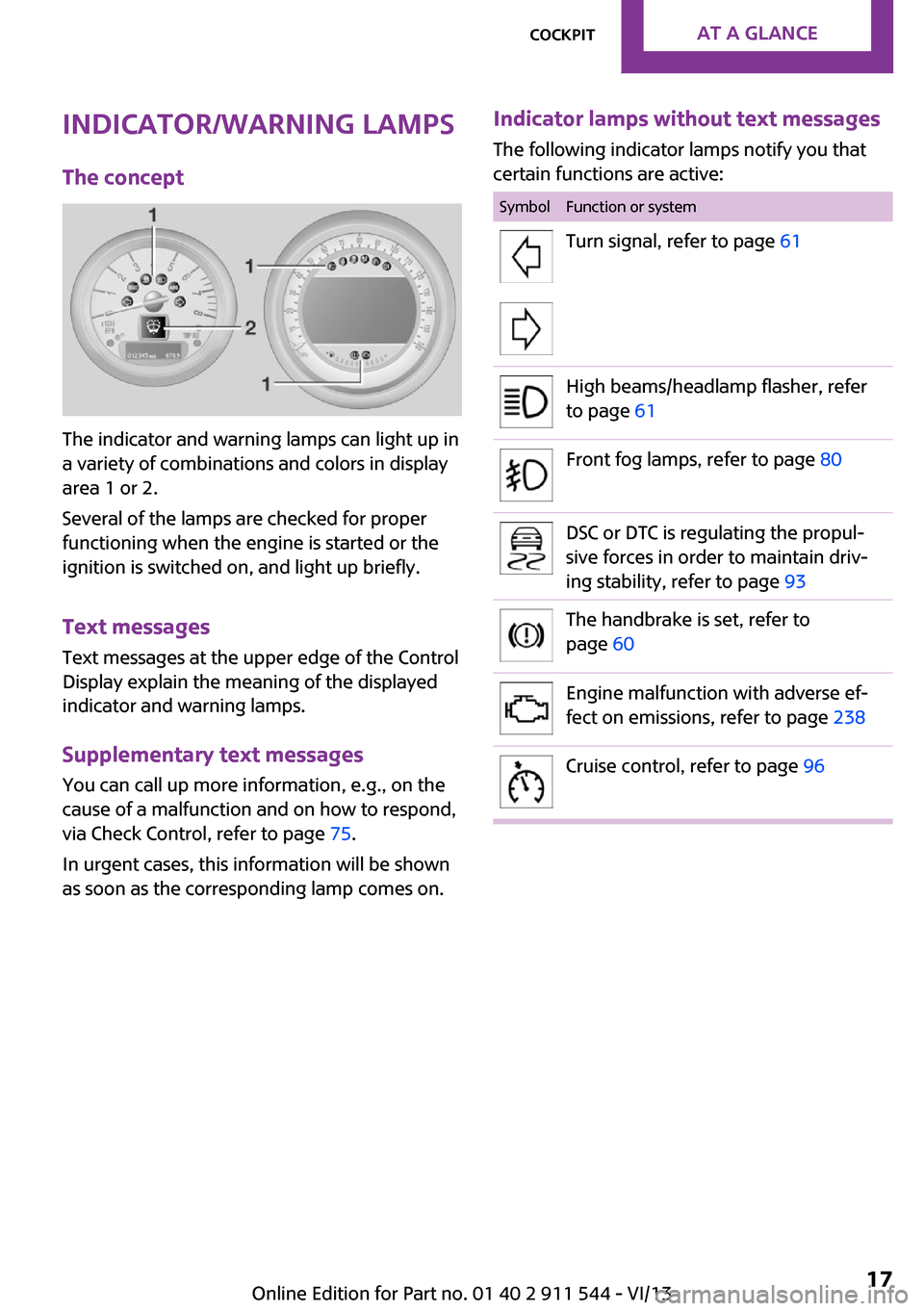
The indicator and warning lamps can light up in
a variety of combinations and colors in display
area 1 or 2.
Several of the lamps are checked for proper
functioning when the engine is started or the
ignition is switched on, and light up briefly.
Text messages
Text messages at the upper edge of the Control
Display explain the meaning of the displayed
indicator and warning lamps.
Supplementary text messages
You can call up more information, e.g., on the
cause of a malfunction and on how to respond,
via Check Control, refer to page 75.
In urgent cases, this information will be shown
as soon as the corresponding lamp comes on.
Indicator lamps without text messages
The following indicator lamps notify you that
certain functions are active:SymbolFunction or systemTurn signal, refer to page 61High beams/headlamp flasher, refer
to page 61Front fog lamps, refer to page 80DSC or DTC is regulating the propul‐
sive forces in order to maintain driv‐
ing stability, refer to page 93The handbrake is set, refer to
page 60Engine malfunction with adverse ef‐
fect on emissions, refer to page 238Cruise control, refer to page 96Seite 17CockpitAt a glance17
Online Edition for Part no. 01 40 2 911 544 - VI/13
Page 19 of 282
All around the head‐
liner1Indicator/warning lamps for the front pas‐
senger airbags 842Reading lamps 81Ambient lighting color 81Glass sunroof, electrical 41Interior lamps 81
All around the shift/
selector lever
1MINI joystick with buttons 212USB audio interface 170Seite 19CockpitAt a glance19
Online Edition for Part no. 01 40 2 911 544 - VI/13
Page 22 of 282

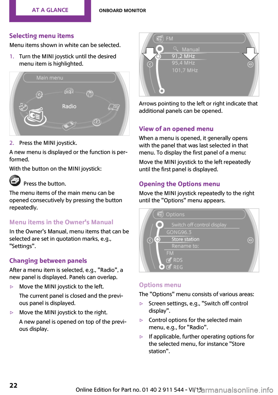
Selecting menu items
Menu items shown in white can be selected.1.Turn the MINI joystick until the desired
menu item is highlighted.2.Press the MINI joystick.
A new menu is displayed or the function is per‐
formed.
With the button on the MINI joystick:
Press the button.
The menu items of the main menu can be
opened consecutively by pressing the button
repeatedly.
Menu items in the Owner's Manual
In the Owner's Manual, menu items that can be
selected are set in quotation marks, e.g.,
"Settings".
Changing between panelsAfter a menu item is selected, e.g., "Radio", a
new panel is displayed. Panels can overlap.
▷Move the MINI joystick to the left.
The current panel is closed and the previ‐
ous panel is displayed.▷Move the MINI joystick to the right.
A new panel is opened on top of the previ‐
ous display.
Arrows pointing to the left or right indicate that
additional panels can be opened.
View of an opened menu
When a menu is opened, it generally opens
with the panel that was last selected in that
menu. To display the first panel of a menu:
Move the MINI joystick to the left repeatedly
until the first panel is displayed.
Opening the Options menu
Move the MINI joystick repeatedly to the right
until the "Options" menu appears.
Options menu
The "Options" menu consists of various areas:
▷Screen settings, e.g., "Switch off control
display".▷Control options for the selected main
menu, e.g., for "Radio".▷If applicable, further operating options for
the selected menu, for instance "Store
station".Seite 22At a glanceOnboard monitor22
Online Edition for Part no. 01 40 2 911 544 - VI/13
Page 23 of 282

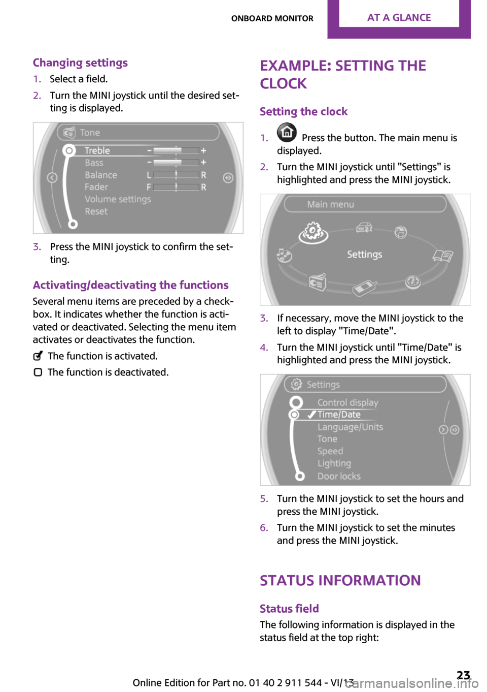
Changing settings1.Select a field.2.Turn the MINI joystick until the desired set‐
ting is displayed.3.Press the MINI joystick to confirm the set‐
ting.
Activating/deactivating the functions
Several menu items are preceded by a check‐box. It indicates whether the function is acti‐
vated or deactivated. Selecting the menu item
activates or deactivates the function.
The function is activated.
The function is deactivated.
Example: setting the
clock
Setting the clock1. Press the button. The main menu is
displayed.2.Turn the MINI joystick until "Settings" is
highlighted and press the MINI joystick.3.If necessary, move the MINI joystick to the
left to display "Time/Date".4.Turn the MINI joystick until "Time/Date" is
highlighted and press the MINI joystick.5.Turn the MINI joystick to set the hours and
press the MINI joystick.6.Turn the MINI joystick to set the minutes
and press the MINI joystick.
Status information
Status fieldThe following information is displayed in the
status field at the top right:
Seite 23Onboard monitorAt a glance23
Online Edition for Part no. 01 40 2 911 544 - VI/13