2014 MINI Paceman ignition
[x] Cancel search: ignitionPage 59 of 282

To save battery power when the engine is off,
switch off the ignition and any unnecessary
electronic systems/power consumers.
Radio ready state and ignition off All indicator and warning lamps in the displays
go out.
The ignition switches off automatically when
the driver's door is opened. Pressing the Start/
Stop button again switches the ignition back
on.
For example, the ignition is not switched off in
the following situations:▷Depress the clutch or brake pedal.▷The low beams are switched on
Starting the engine
General information Enclosed areas
Do not let the engine run in enclosed
areas; otherwise, breathing of exhaust fumes
may lead to loss of consciousness and death.
The exhaust gases contain carbon monoxide,
an odorless and colorless but highly toxic gas. ◀
Unattended vehicle
Do not leave the car unattended with the
engine running; otherwise, it presents a poten‐
tial source of danger.
Before leaving the car with the engine running,
shift to neutral or engage transmission posi‐
tion P and set the handbrake firmly; otherwise,
the vehicle may begin to roll. ◀
Frequent starting in quick succession
Avoid repeated futile attempts at starting
the car and avoid starting the car frequently in
quick succession. Otherwise, the fuel is not
burned or is inadequately burned, and there is
the danger of overheating and damaging the
catalytic converter. ◀
Do not wait for the engine to warm-up while
the vehicle remains stationary; start driving
right away, but at moderate engine speeds.
Do not depress the accelerator when starting
the engine.
Starting the engine
Manual transmission
Remote control in the ignition lock or, with
Comfort Access, inside the vehicle, refer to
page 38.
1.Depress the brake pedal.2.Depress the clutch pedal.3.Press the Start/Stop button.
The ignition is activated automatically for a cer‐
tain time and is stopped as soon as the engine
starts.
Automatic transmission
Remote control in the ignition lock or, with
Comfort Access, inside the vehicle, refer to
page 38.
1.Depress the brake pedal.2.Move the selector lever to position P or N.3.Press the Start/Stop button.
The ignition is activated automatically for a cer‐
tain time and is stopped as soon as the engine
starts.
Seite 59DrivingControls59
Online Edition for Part no. 01 40 2 911 544 - VI/13
Page 62 of 282

3Activating/deactivating intermittent wipe or
the rain sensor4Cleaning the windshield and headlamps
Switching on wipers
Press the wiper lever upward, arrow 1.
The lever automatically returns to its initial po‐
sition when released.
Normal wiper speed
Press up once.
The system switches to operation in the inter‐
mittent mode when the vehicle is stationary.
Fast wiper speed
Press up twice or press once beyond the resist‐
ance point.
The system switches to normal speed when the
vehicle is stationary.
Switching off wipers or brief wipe Press the wiper lever down, arrow 2.
The lever automatically returns to its initial po‐
sition when released.
▷Brief wipe: press down once.▷To switch off normal wipe: press down
once.▷To switch off fast wipe: press down twice.
Intermittent wipe or rain sensor
If the car is not equipped with a rain sensor, the
intermittent-wipe time is a preset.
If the car is equipped with a rain sensor, the
time between wipes is controlled automatically
and depends on the intensity of the rainfall.
The rain sensor is mounted on the windshield,
directly in front of the interior rearview mirror.
Deactivate the rain sensor in car washes
Deactivate the rain sensor when passing
through an automatic car wash; otherwise,
damage could be caused by undesired wiper
activation. ◀
Activating intermittent wipe or rain
sensor
Press the button, arrow 3.
The symbol is shown in the tachometer.
Setting the sensitivity of the rain sensor1.Switch on the ignition, refer to page 58.2.Press the button on the turn indicator lever
repeatedly until "SET/INFO" is displayed.3.Press and hold the button until the display
changes.4.Press the button repeatedly until the sym‐
bol and "SET" are displayed.Seite 62ControlsDriving62
Online Edition for Part no. 01 40 2 911 544 - VI/13
Page 63 of 282

5.Press and hold the button until the display
changes.6.Press the button to select the desired sensi‐
tivity.7.Wait or hold the button until the display
changes.
The settings were stored.
Deactivating intermittent wipe or rain
sensor
Press the button again, arrow 3.
Cleaning the windshield and headlamps
Pull the lever, arrow 4.
The system sprays washer fluid on the wind‐
shield and activates the wipers briefly.
When the vehicle lighting system is switched
on, the headlamps are cleaned at regular and
appropriate intervals.
Do not use the washer system at freezing
temperatures
Do not use the washers if there is any danger
that the fluid will freeze on the windshield; oth‐
erwise, your vision could be obscured. For this
reason, use antifreeze.
Avoid using the washer when the reservoir is
empty; otherwise, you could damage the
pump. ◀
Do not use the washing facilities when
the hood is open
Only use the washing facilities when the hood
is fully locked; otherwise, the headlamp washer
system may become damaged. ◀
Windshield washer nozzles The windshield washer nozzles are heated au‐
tomatically while the engine is running or the
ignition is switched on.
Rear window wiper0Resting position1Switching on intermittent wipe
Turn the cap to level 1.
When reverse gear is engaged, the system
switches to continuous operation.2Cleaning the rear window with intermittent
wipe
Turn the cap further to level 2 and hold.3Cleaning the rear window in the resting po‐
sition
Turn the cap to level 3 and hold.
The rear window wiper does not move if the
cap is in position 1 before the ignition is
switched on.
To switch on the rear window wiper:
1.Move the cap to its basic position.2.Select the required position again.Seite 63DrivingControls63
Online Edition for Part no. 01 40 2 911 544 - VI/13
Page 65 of 282

Reverse gearSelect only when the vehicle is stationary. When
the gearshift lever is pressed to the left, a slight
resistance needs to be overcome.
Automatic transmission
with Steptronic
In addition to the fully automatic mode, gears
can also be shifted manually using Steptronic,
refer to page 66.
Parking the vehicle Secure the vehicle
Before leaving the vehicle with the en‐
gine running, move the selector lever to posi‐
tion P and set the handbrake; otherwise, the
vehicle will begin moving. ◀
Disengaging the remote control
To remove the remote control from the ignition
lock, first move the selector lever to position P
and switch off the engine: interlock. Remove
the remote control from the ignition lock, refer
to page 58.
Selector lever positions
P R N D M/S + –
Displays in the tachometer
The selector lever position is displayed and the
engaged gear, such as M4, is displayed in
manual mode.
Changing selector lever positions▷With the ignition switched on or the engine
running, the selector lever can be moved
out of position P.▷When the vehicle is stationary, step on the
brake before shifting out of P or N; other‐
wise, the selector lever is locked: shiftlock.
Press on the brake pedal until you
start driving
To prevent the vehicle from creeping after
you select a driving position, maintain pres‐
sure on the brake pedal until you are ready
to start. ◀
A lock prevents accidental shifting into selector
lever positions R and P.
To override the lock, press the button on the
front of the selector lever, see arrow.
P Park
Select only when the vehicle is stationary. The
front wheels are blocked.
R is Reverse
Select only when the vehicle is stationary.
N is NeutralFor example, engage this position in a car
wash. The vehicle can roll.
D Drive, automatic position Position for normal vehicle operation. All for‐
ward gears are selected automatically.
Seite 65DrivingControls65
Online Edition for Part no. 01 40 2 911 544 - VI/13
Page 67 of 282

Manually unlocking the selector lever
lock
If the selector lever is locked in position P al‐
though the ignition is switched on, the brake is
depressed, and the button on the selector lever
is pressed, the selector lever lock can be over‐
ridden:1.Switch off the ignition.2.Unclip the sleeve of the selector lever.3.Pull the sleeve up over the selector lever
until the sleeve is inside out.
Pull off the plug-in cable connector if nec‐
essary.4.Insert the pulling hook 1 into the loop on
the passenger side.
The pulling hook is found in the vehicle
document portfolio or in the pouch of the
wheel change set, refer to page 245.5.Pull the loop upward.6.Move the selector lever into the desired po‐
sition, pressing the button on the front of
the selector lever.
Set the handbrake
Before manually unlocking the selector
lever lock, pull the handbrake firmly; otherwise,
the vehicle may roll away and cause personal
injury or property damage. ◀
Seite 67DrivingControls67
Online Edition for Part no. 01 40 2 911 544 - VI/13
Page 71 of 282

Resetting the fuel consumption and
speed
Resetting the values for average speed and
average fuel consumption:1.Select the respective menu item and press
the MINI joystick.2.Press the MINI joystick again to confirm
your selection.
Resetting the trip computer
Resetting all values:
1."Vehicle Info"2."Trip computer"3."Reset"
Settings and information
Operating concept
Some settings and information can only be cre‐
ated or opened while the ignition is switched
on, the vehicle is standing, and the doors are
closed.
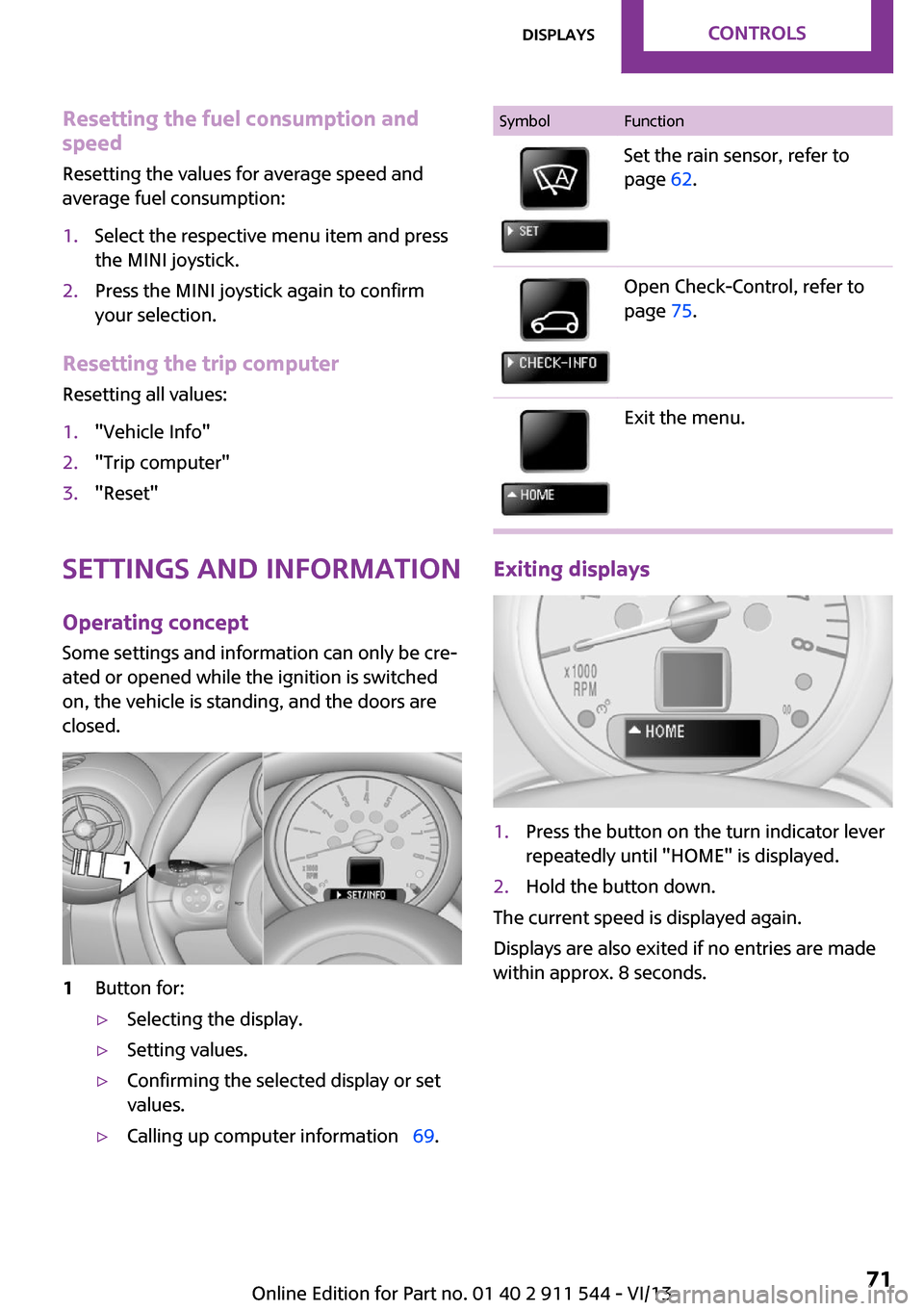
1Button for:▷Selecting the display.▷Setting values.▷Confirming the selected display or set
values.▷Calling up computer information 69.SymbolFunctionSet the rain sensor, refer to
page 62.Open Check-Control, refer to
page 75.Exit the menu.
Exiting displays
1.Press the button on the turn indicator lever
repeatedly until "HOME" is displayed.2.Hold the button down.
The current speed is displayed again.
Displays are also exited if no entries are made
within approx. 8 seconds.
Seite 71DisplaysControls71
Online Edition for Part no. 01 40 2 911 544 - VI/13
Page 74 of 282

Brightness
The brightness is automatically adapted to the
ambient lighting conditions. However, the basic
setting can be changed when the low beams
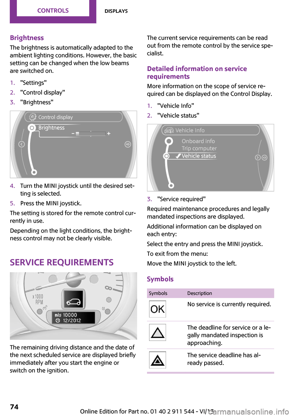
are switched on.1."Settings"2."Control display"3."Brightness"4.Turn the MINI joystick until the desired set‐
ting is selected.5.Press the MINI joystick.
The setting is stored for the remote control cur‐
rently in use.
Depending on the light conditions, the bright‐
ness control may not be clearly visible.
Service requirements
The remaining driving distance and the date of
the next scheduled service are displayed briefly
immediately after you start the engine or
switch on the ignition.
The current service requirements can be read
out from the remote control by the service spe‐
cialist.
Detailed information on service
requirements
More information on the scope of service re‐
quired can be displayed on the Control Display.1."Vehicle Info"2."Vehicle status"3."Service required"
Required maintenance procedures and legally
mandated inspections are displayed.
Additional information can be displayed on
each entry:
Select the entry and press the MINI joystick.
To exit from the menu:
Move the MINI joystick to the left.
Symbols
SymbolsDescriptionNo service is currently required.The deadline for service or a le‐
gally mandated inspection is
approaching.The service deadline has al‐
ready passed.Seite 74ControlsDisplays74
Online Edition for Part no. 01 40 2 911 544 - VI/13
Page 75 of 282

Entering appointment dates
Enter the dates for the required inspections.
Make sure the date on the Control Display is set
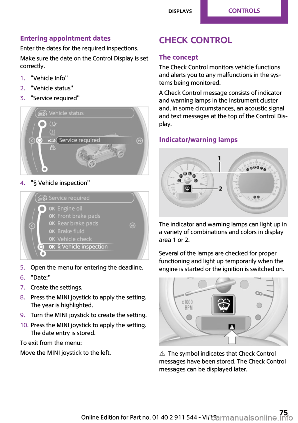
correctly.1."Vehicle Info"2."Vehicle status"3."Service required"4."§ Vehicle inspection"5.Open the menu for entering the deadline.6."Date:"7.Create the settings.8.Press the MINI joystick to apply the setting.
The year is highlighted.9.Turn the MINI joystick to create the setting.10.Press the MINI joystick to apply the setting.
The date entry is stored.
To exit from the menu:
Move the MINI joystick to the left.
Check Control
The concept
The Check Control monitors vehicle functions
and alerts you to any malfunctions in the sys‐
tems being monitored.
A Check Control message consists of indicator
and warning lamps in the instrument cluster
and, in some circumstances, an acoustic signal
and text messages at the top of the Control Dis‐
play.
Indicator/warning lamps
The indicator and warning lamps can light up in
a variety of combinations and colors in display
area 1 or 2.
Several of the lamps are checked for proper
functioning and light up temporarily when the
engine is started or the ignition is switched on.
The symbol indicates that Check Control
messages have been stored. The Check Control
messages can be displayed later.
Seite 75DisplaysControls75
Online Edition for Part no. 01 40 2 911 544 - VI/13