Page 233 of 276

rates after a short time. The headlamps do not
need to be changed.
If the condensation in the headlamps does not
evaporate after trips with the lights switched
on, and the amount of moisture in the head‐
lamps increases, for example if water droplets
form, have them checked by your service cen‐
ter.
Bi-xenon headlamps These bulbs have a very long life and the likeli‐
hood of failure is very low, provided that they
are not switched on and off excessively. If a
bulb should nevertheless fail, you can continue
driving cautiously with the front fog lamps, pro‐
vided this is permitted by local laws.
Do not perform work/bulb replacement
on xenon headlamps
Have any work on the xenon lighting system,
including bulb replacement, performed only by
a service center.
Due to the high voltage present in the system,
there is the danger of fatal injuries if work is
carried out improperly. ◀
Front lamps, bulb replacement
Halogen low beams and high beams
Bulb H13, 60/55 watt
Wear protective goggles and gloves
Halogen bulbs are pressurized. Therefore,
wear protective goggles and gloves. Otherwise,
there is a danger of injuries if the bulb is acci‐
dentally damaged during replacement. ◀
Attach the cover carefully
When attaching the cover, proceed care‐
fully; otherwise, leaks may occur, causing dam‐
age to the headlamp system. ◀Access to the bulbs through the engine
compartment
Follow the general instructions on lamps and
bulbs, refer to page 232.
Low beam/high beam bulbs can be changed
from the engine compartment.
To remove the cover:
1.Press the tab.2.Fold away the cover and take it out of the
holder.
Proceed in reverse order to attach the cover.
Attach the cover carefully
When attaching the cover, proceed care‐
fully; otherwise, leaks may occur, causing dam‐
age to the headlamp system. ◀
Replacing the bulb
1.Turn the bulb counterclockwise, arrow 1,
and remove it, arrow 2.Seite 233Replacing componentsMobility233
Online Edition for Part no. 01 40 2 911 452 - VI/13
Page 234 of 276
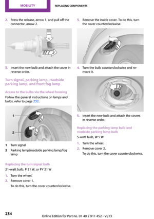
2.Press the release, arrow 1, and pull off the
connector, arrow 2.3.Insert the new bulb and attach the cover in
reverse order.
Turn signal, parking lamp, roadside
parking lamp, and front fog lamp
Access to the bulbs via the wheel housing
Follow the general instructions on lamps and
bulbs, refer to page 232.
1Turn signal2Parking lamp/roadside parking lamp/fog
lamp
Replacing the turn signal bulb
21-watt bulb, P 21 W, or PY 21 W
1.Turn the wheel.2.Remove cover 1.
To do this, turn the cover counterclockwise.3.Remove the inside cover. To do this, turn
the cover counterclockwise.4.Turn the bulb counterclockwise and re‐
move it.5.Insert the new bulb and attach the covers
in reverse order.
Replacing the parking lamp bulb and
roadside parking lamp bulb
5-watt bulb, W 5 W
1.Turn the wheel.2.Remove cover 2.
To do this, turn the cover counterclockwise.Seite 234MobilityReplacing components234
Online Edition for Part no. 01 40 2 911 452 - VI/13
Page 235 of 276

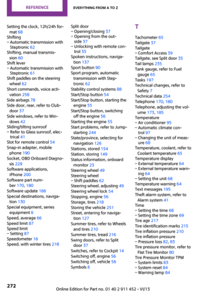
3.Turn the upper bulb counterclockwise and
remove it.4.Insert the new bulb and attach the cover in
reverse order.
Replacing the front fog lamp bulb
H8 bulb, 35 watt
1.Turn the wheel.2.Remove cover 2.
To do this, turn the cover counterclockwise.3.Pull off the plug-in cable connector.4.Turn the lower bulb counterclockwise and
remove it.5.Insert the new bulb and attach the cover in
reverse order.Lateral turn signals
5-watt bulb, W 5 W1.Push the lamp forward with the air grille
and remove it.2.Turn the bulb holder counterclockwise and
remove it.3.Pull out the bulb and replace it.4.Insert the new bulb and attach the cover in
reverse order.
Tail lamps, bulb replacement
Follow the general instructions on lamps and
bulbs, refer to page 232.
Turn signal: 21-watt bulb, PY 21 W
Brake lamp: 21-watt/5-watt bulb, W 5 W
Remaining lamps: 21-watt bulb, P 21 W
MINI
1Turn signal2Tail lamp LED3Brake lampSeite 235Replacing componentsMobility235
Online Edition for Part no. 01 40 2 911 452 - VI/13
Page 236 of 276
MINI Clubman1Brake lamp2Turn signal3Tail lamp LED4Rear fog lamp/backup lamp
Replacing
MINI
1.Remove the cover of the cargo area side
wall.2.Turn the corresponding bulb counterclock‐
wise, arrows 1, and remove.
Another bulb is located behind the cargo
area side wall, arrow 2.3.Insert the new bulb and attach the cover in
reverse order.
MINI Clubman
1.Unscrew the screw at the top with the
screwdriver from the onboard vehicle tool
kit.2.Swing out the tail lamp and remove toward
the top.3.Pull off the plug-in cable connector if nec‐
essary, arrow 1.4.Turn the corresponding bulb counterclock‐
wise, arrows 2, and remove.5.Insert the new bulb and install the tail lamp
in reverse order.
MINI: rear fog lamp/backup lamps
16-watt bulbs, W 16W
The lamps are accessed via the rear side or the
underside of the bumper.
Seite 236MobilityReplacing components236
Online Edition for Part no. 01 40 2 911 452 - VI/13
Page 237 of 276

1.Squeeze the clips, arrows, and remove the
bulb holder.2.Pull off the bulb and replace it.3.Insert the new bulb and bulb holder in re‐
verse order.4.Re-engage the bulb holder so that it audi‐
bly clicks into place.
MINI Clubman: the rear fog lamp is located in
the left tail lamp, refer to page 235.
John Cooper Works: aerodynamic bumper
1.Remove the bulb holder by turning it coun‐
terclockwise, arrow.2.Pull off the bulb and replace it.3.Insert the new bulb and bulb holder in re‐
verse order.
License plate lamps
5-watt bulb, C 5 W
Replacing
MINI1.Push the lamp to the left in the catch of the
lamp housing using the screwdriver, ar‐
row 1.2.Take out the lamp, arrow 2.3.Replace the bulb.4.Insert the lamp.
MINI Clubman
1.Push the lamp to the left in the catch of the
lamp housing using the screwdriver, ar‐
row 1.2.Take out the lamp, arrow 2.3.Replace the bulb.4.Insert the lamp.
Center brake lamp
This lamp uses LED technology for operation.
Contact your service center in the event of a
malfunction.
Seite 237Replacing componentsMobility237
Online Edition for Part no. 01 40 2 911 452 - VI/13
Page 238 of 276

Changing wheelsNotes
Wheel change for run-flat tires:▷Prepare for the wheel change, refer to
page 239.▷Jack up the vehicle, refer to page 239.▷Tighten the lug bolts, refer to page 240.
Compact wheel
Wheel change with a compact wheel:
▷Remove the compact wheel, refer to
page 238.▷Prepare for the wheel change, refer to
page 239.▷Jack up the vehicle, refer to page 239.▷Mount the compact wheel, refer to
page 240.▷Tighten the lug bolts, refer to page 240.▷Drive with the compact wheel, refer to
page 239.
MINI: removing the compact wheel
The screw fitting of the compact wheel is lo‐
cated in the cargo area under the floor mat, on
the floor of the storage compartment holding
the wheel change set.
1.Release the screw fitting with the special
wrench.2.Take out the cover.3.Screw the lifting handle from the onboard
vehicle tool kit onto the thread.4.Raise the lifting handle slightly.5.Squeeze the locking spring.6.Lower the compact wheel with the lifting
handle.7.Lower the compact wheel with the lifting
handle.8.Unscrew the lifting handle again.9.Pull the compact wheel out from under the
vehicle toward the back.10.Lay the compact wheel down with the
valve facing up.Seite 238MobilityReplacing components238
Online Edition for Part no. 01 40 2 911 452 - VI/13
Page 239 of 276

11.Unscrew the valve extension from the valve
of the compact wheel.12.Unscrew the dust cap from the extension
and attach it to the valve of the compact
wheel.
The defective wheel cannot be stowed in the
compact wheel holder because it has a differ‐
ent size.
MINI Clubman: removing the compact
wheel
The compact wheel is located under the wheel
change set in the cargo area.
1.Fold up the floor mat.2.Unscrew the nut, arrow, and take out the
compact wheel.
Driving with compact wheel
Do not exceed a speed of
50 mph/80 km/h.
Drive conservatively and do not exceed a speed
of 50 mph/80 km/h. Otherwise, changes in the
driving characteristics could result, for example
reduced track stability on braking, extended
braking distance, and altered self-steering
characteristics in the limit range. In conjunction
with winter tires, these characteristics are more
pronounced. ◀
Only mount one compact wheel
Only one compact wheel may be
mounted. Restore the wheels and tires to their
original size as quickly as possible. Failure to do
so is a safety risk. ◀
Check the tire inflation pressure at the next op‐
portunity and correct it if necessary. Replace
the defective tire as soon as possible and have
the new wheel balanced.
Preparing wheel change
Observe the safety precautions regarding flat
tires, refer to page 219.
Additional safety precautions in the event
of a wheel change
Change the wheel only on a level, firm surface
which is not slippery.
The vehicle or the jack could slip to the side if
you attempt to raise the vehicle on a soft or
slippery surface, snow, ice, tiles, etc. Do not use
a wooden block or similar object as a support
base for the jack, as this would prevent it from
extending to its full support height and reduce
its load-carrying capacity.
To avoid serious or fatal injury: never lie under
the vehicle, and never start the engine while it
is supported by the jack. ◀1.Place the folding wheel chock behind the
front wheel of the other vehicle side; if the
vehicle is on an incline, place it in front of
this wheel. If the vehicle is parked on a
steep incline, additionally secure the vehi‐
cle against rolling.2.Expose the lug bolts if necessary.3.Loosen the lug bolts a half turn.
Jacking up vehicle
Seite 239Replacing componentsMobility239
Online Edition for Part no. 01 40 2 911 452 - VI/13
Page 240 of 276

The vehicle jack is designed for changing
wheels only.
The vehicle jack is designed for changing
wheels only. Do not attempt to raise another
vehicle model with it or to raise any load of any
kind. To do so could cause accidents and per‐
sonal injury. ◀1.Position the vehicle jack at the jacking point
closest to the wheel.
The entire surface of the jack base must
rest on the ground vertically beneath the
jacking point.2.Guide the jack head into the rectangular re‐
cess of the jacking point when cranking up.3.Jack the vehicle up until the wheel you are
changing is raised from the ground.
Mounting the compact wheel
1.Unscrew the lug bolts and remove the
wheel.2.Remove accumulations of mud or dirt from
the mounting surfaces of the wheel and
hub. Also clean the lug bolts.3.Mount the new wheel.4.Screw in at least two bolts crosswise.5.Screw in the remaining lug bolts.6.Fully tighten all lug bolts in a diagonal pat‐
tern.7.Lower the vehicle.8.Remove the jack.Retightening the lug bolts
Retighten the lug bolts diagonally.
Checking that the lug bolts are tight
Always have the lug bolts checked with a
calibrated torque wrench as soon as possible to
ensure that they are tightened to the specified
torque. Otherwise, incorrectly tightened lug
bolts are a hidden safety risk. ◀
The tightening torque equals
103.3 lb ft/140 Nm.
Replace the defective tire as soon as possible
and have the new wheel balanced.
Vehicle battery Maintenance
The battery is maintenance-free, i.e., the elec‐
trolyte will last for the life of the battery in tem‐
perate climate conditions.
The service center will be happy to answer any
questions on the battery.
Battery replacement Use approved vehicle batteries
Only use vehicle batteries that have been
approved for your vehicle by the manufacturer;
otherwise, the vehicle could be damaged and
systems or functions may not be fully availa‐
ble. ◀
Have the vehicle battery registered by the serv‐
ice center after it is replaced to ensure that all comfort functions are available without restric‐
tions and that any associated Check Control
messages are no longer displayed.Seite 240MobilityReplacing components240
Online Edition for Part no. 01 40 2 911 452 - VI/13