2014 MERCEDES-BENZ SLS AMG GT COUPE lights
[x] Cancel search: lightsPage 197 of 290

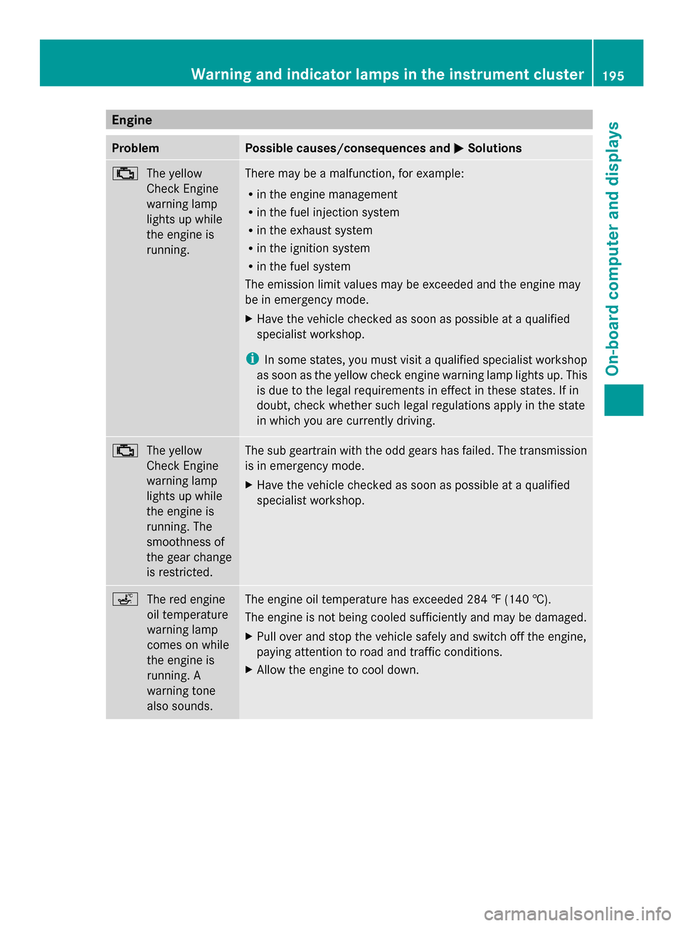
Engine
Problem Possible causes/consequences and
0050
0050Solutions 00B9
The yellow
Check Engine
warning lamp
lights up while
the engine is
running. There may be a malfunction, for example:
R
in the engine management
R in the fuel injection system
R in the exhaust system
R in the ignition system
R in the fuel system
The emission limit values may be exceeded and the engine may
be in emergency mode.
X Have the vehicle checked as soon as possible at a qualified
specialist workshop.
i In some states, you must visit a qualified specialist workshop
as soon as the yellow check engine warning lamp lights up. This
is due to the legal requirements in effect in these states. If in
doubt, check whether such legal regulations apply in the state
in which you are currently driving. 00B9
The yellow
Check Engine
warning lamp
lights up while
the engine is
running. The
smoothness of
the gear change
is restricted. The sub geartrain with the odd gears has failed. The transmission
is in emergency mode.
X
Have the vehicle checked as soon as possible at a qualified
specialist workshop. 00E4
The red engine
oil temperature
warning lamp
comes on while
the engine is
running. A
warning tone
also sounds. The engine oil temperature has exceeded 284 ‡ (140 †).
The engine is not being cooled sufficiently and may be damaged.
X
Pull over and stop the vehicle safely and switch off the engine,
paying attention to road and traffic conditions.
X Allow the engine to cool down. Warning and indicator lamps in the instrument cluster
195On-board computer and displays Z
Page 198 of 290

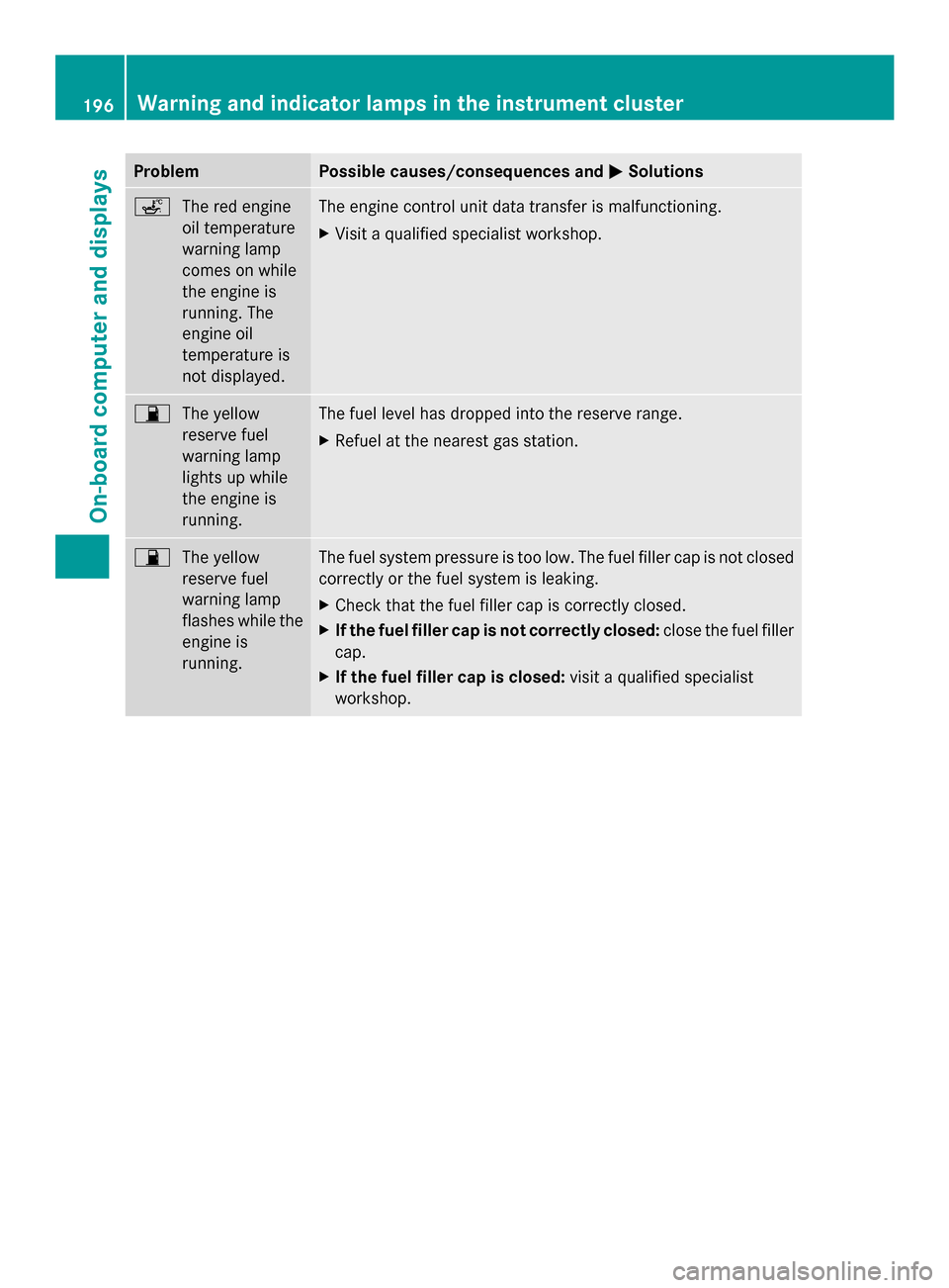
Problem Possible causes/consequences and
0050
0050Solutions 00E4
The red engine
oil temperature
warning lamp
comes on while
the engine is
running. The
engine oil
temperature is
not displayed. The engine control unit data transfer is malfunctioning.
X
Visit a qualified specialist workshop. 00B5
The yellow
reserve fuel
warning lamp
lights up while
the engine is
running. The fuel level has dropped into the reserve range.
X
Refuel at the nearest gas station. 00B5
The yellow
reserve fuel
warning lamp
flashes while the
engine is
running. The fuel system pressure is too low. The fuel filler cap is not closed
correctly or the fuel system is leaking.
X
Check that the fuel filler cap is correctly closed.
X If the fuel filler cap is not correctly closed: close the fuel filler
cap.
X If the fuel filler cap is closed: visit a qualified specialist
workshop. 196
Warning and indicator lamps in the instrument clusterOn-board computer and displays
Page 212 of 290

enforcement agency is informed of the
location of the vehicle.
i If the anti-theft alarm system is active for
longer than 30 seconds, mbrace
automatically informs the Mercedes-Benz
Customer Assistance Center. Rear spoiler
The rear spoiler improves the handling of the
vehicle. It adapts the vehicle's aerodynamics
to the operating conditions, dependent on the
speed of the vehicle. Example: Coupe
i
If the vehicle is equipped with AMG
adaptive sport suspension system, the
button is in the switch strip above the air
conditioning control panel.
Only use button 0043to extend and retract the
rear spoiler manually for cleaning.
Button 0043is not used to operate the rear
spoiler.
If you drive at speeds above 75 mph
(120 km/h), the rear spoiler extends
automatically. Button 0043flashes until the rear
spoiler has extended and then lights up in red.
If you drive at speeds above 50 mph
(80 km/h), the rear spoiler remains
extended. Button 0043remains lit in red.
If you drive at speeds below 50 mph
(80 km/h), the rear spoiler retracts
automatically. Button 0043flashes until the rear
spoiler has retracted and then goes out. Extending and retracting the rear
spoiler manually You can extend and retract the rear spoiler
manually for cleaning.
G
WARNING
Body parts could become trapped if you
manually retract the rear spoiler. There is a
risk of injury.
Make sure that nobody is within the range of
movement of the rear spoiler. Release the
switch immediately if somebody becomes
trapped. The rear spoiler then extends again.
When leaving the vehicle, always take the
SmartKey with you and lock the vehicle. Never
leave children unsupervised in the vehicle.
! Do not enter an automatic car wash with
the rear spoiler extended. Otherwise, the
rear spoiler may be damaged.
Only extend the rear spoiler in order to
clean it by hand. Retract it again when you
have finished cleaning it.
X Close the trunk lid.
X Select key position 2with the Start/Stop
button (Y page 119).
X To extend: press button 0043.
The rear spoiler is extended.
Button 0043flashes until the rear spoiler has
extended and then lights up in red.
X To retract: press and hold button 0043until
the rear spoiler is completely retracted.
Button 0043flashes until the rear spoiler has
retracted and then goes out.
Rear Spoiler retracts manually Rear Spoiler retracts manually
appears in the display.
i If you release button 0043while retracting
the rear spoiler, it extends again
automatically. 210
FeaturesStowage and features
Page 214 of 290

Alternatively, you can call the following
telephone assistance services:
R USA: Mercedes-Benz Customer
Assistance Center at
1-800-FOR-MERCedes
R Canada: Customer Service at
1-800-387-0100
i Notes about the declaration of conformity
can be found here (Y page 22).
USA: FCC ID: CB2HMIHL4
Canada: IC: 279B-HMIHL4
Programming Programing buttons
Pay attention to the "Important safety notes"
(Y page 211). Integrated garage door opener in the rear-view
mirror
Garage door remote control 0083is not part of
the integrated garage door opener.
X Before programing for the first time, clear
the integrated garage door opener memory
(Y page 214).
X Select key position 2with the Start/Stop
button ( Ypage 119).
X Press and hold one of buttons 0044to0085 on
the integrated garage door opener.
After a short time, indicator lamp 0043lights
up yellow.
i Indicator lamp 0043lights up yellow as soon
as button 0044,0087or0085 is programed for the
first time. If the selected button has already
been programed, indicator lamp 0043will only light up yellow after ten seconds have
elapsed.
X Release button 0044,0087or0085.
Indicator lamp 0043flashes yellow.
X Point garage door remote control 0083
towards buttons 0044to0085 on the rear-view
mirror at a distance of 2 to 8 inches (5 to
20 cm).
i The required distance between remote
control 0083and the integrated garage door
opener depends on the garage door drive
system. Several attempts might be
necessary. You should test every position
for at least 25 seconds before trying
another position.
X Press and hold button 0084on remote control
0083 until indicator lamp 0043lights up green.
If indicator lamp 0043lights up green or
flashes, then programing was successful.
X Release button 0084on remote control 0083for
the garage door drive system.
X If indicator lamp 0043lights up red: repeat
the programing procedure for the
corresponding button on the rear-view
mirror. When doing so, vary the distance
between remote control 0083and the rear-
view mirror.
i If the indicator lamp flashes green after
successful programing, the garage door
system is using a rolling code. After
programing, you must synchronize the
garage door opener integrated in the rear-
view mirror with the receiver of the garage
door system.
Synchronizing the rolling code
Pay attention to the "Important safety notes"
(Y page 211).
Your vehicle must be within reach of the
garage door or exterior gate drive. Make sure
that neither your vehicle nor any persons/
objects are present within the sweep of the
door or gate. 212
FeaturesSto
wage an d features
Page 215 of 290

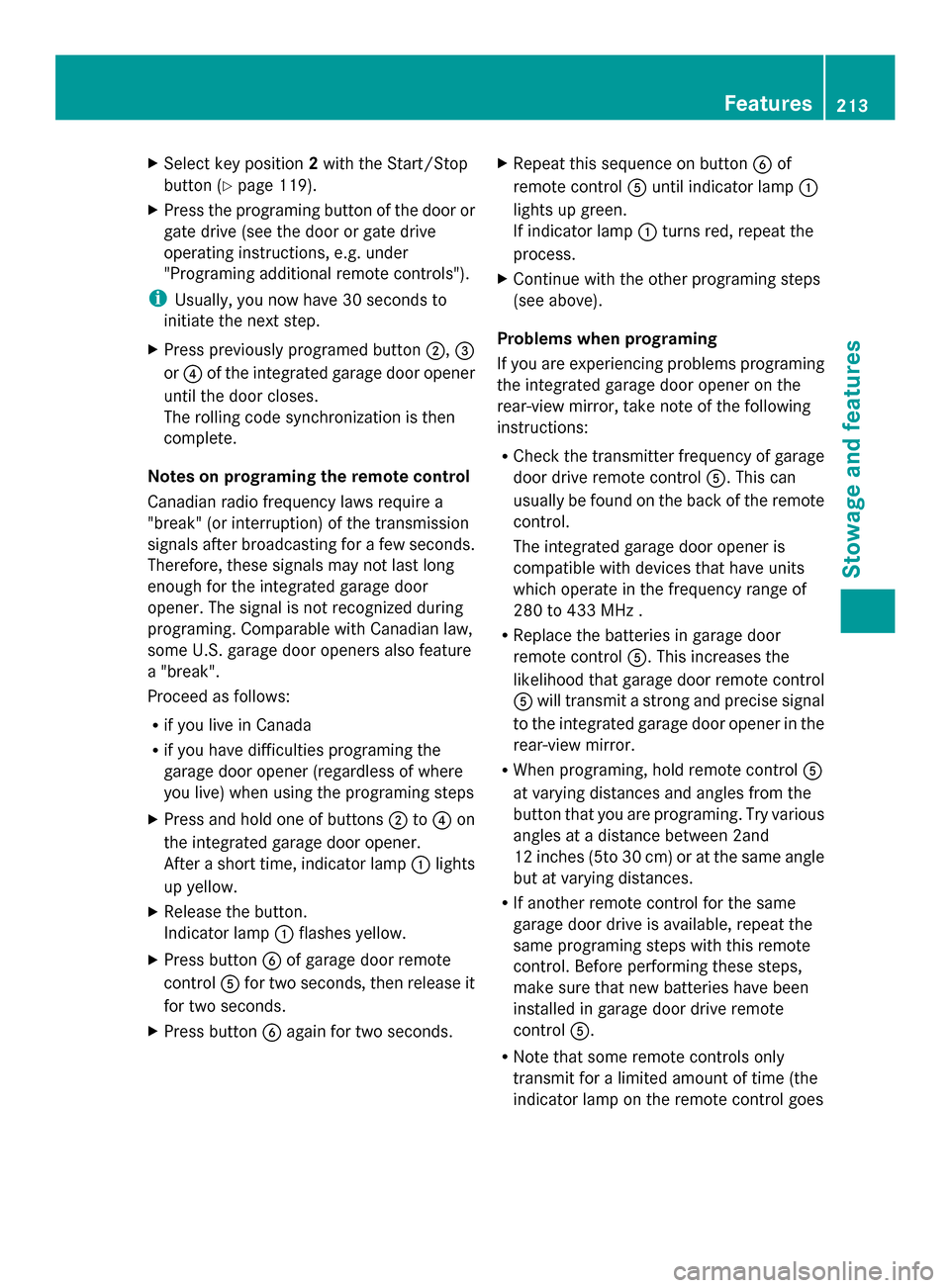
X
Select key position 2with the Start/Stop
button (Y page 119).
X Press the programing button of the door or
gate drive (see the door or gate drive
operating instructions, e.g. under
"Programing additional remote controls").
i Usually, you now have 30 seconds to
initiate the next step.
X Press previously programed button 0044,0087
or 0085 of the integrated garage door opener
until the door closes.
The rolling code synchronization is then
complete.
Notes on programing the remote control
Canadian radio frequency laws require a
"break" (or interruption) of the transmission
signals after broadcasting for a few seconds.
Therefore, these signals may not last long
enough for the integrated garage door
opener. The signal is not recognized during
programing. Comparable with Canadian law,
some U.S. garage door openers also feature
a "break".
Proceed as follows:
R if you live in Canada
R if you have difficulties programing the
garage door opener (regardless of where
you live) when using the programing steps
X Press and hold one of buttons 0044to0085 on
the integrated garage door opener.
After a short time, indicator lamp 0043lights
up yellow.
X Release the button.
Indicator lamp 0043flashes yellow.
X Press button 0084of garage door remote
control 0083for two seconds, then release it
for two seconds.
X Press button 0084again for two seconds. X
Repeat this sequence on button 0084of
remote control 0083until indicator lamp 0043
lights up green.
If indicator lamp 0043turns red, repeat the
process.
X Continue with the other programing steps
(see above).
Problems when programing
If you are experiencing problems programing
the integrated garage door opener on the
rear-view mirror, take note of the following
instructions:
R Check the transmitter frequency of garage
door drive remote control 0083. This can
usually be found on the back of the remote
control.
The integrated garage door opener is
compatible with devices that have units
which operate in the frequency range of
280 to 433 MHz .
R Replace the batteries in garage door
remote control 0083. This increases the
likelihood that garage door remote control
0083 will transmit a strong and precise signal
to the integrated garage door opener in the
rear-view mirror.
R When programing, hold remote control 0083
at varying distances and angles from the
button that you are programing. Try various
angles at a distance between 2and
12 inches (5to 30 cm) or at the same angle
but at varying distances.
R If another remote control for the same
garage door drive is available, repeat the
same programing steps with this remote
control. Before performing these steps,
make sure that new batteries have been
installed in garage door drive remote
control 0083.
R Note that some remote controls only
transmit for a limited amount of time (the
indicator lamp on the remote control goes Features
213Stowage and features Z
Page 216 of 290

out). Press button
0084on remote control
0083 again before transmission ends.
R Align the antenna cable of the garage door
opener unit. This can improve signal
reception/transmission.
Opening/closing the garage door Once programed, the integrated garage door
opener 0083will assume the function of the
garage door system's remote control. Please
also read the operating instructions for the
garage door system.
X Select key position 2with the Start/Stop
button.
X Press button 0044,0087or0085 which you have
programed to operate the garage door.
Garage door system with a fixed code:
indicator lamp 0043lights up green.
Garage door system with a rolling code:
indicator lamp 0043flashes green.
i The transmitter will transmit a signal as
long as the button is pressed. The
transmission is halted after a maximum of
ten seconds and indicator lamp 0043lights
up yellow. Press button 0044,0087or0085 again
if necessary.
Clearing the memory X
Select key position 2with the Start/Stop
button.
X Press buttons 0044and 0085.
The indicator lamp lights up yellow.
X Press and hold buttons 0044and 0085until the
indicator lamp turns green.
i Make sure that you clear the memory of
the integrated garage door opener before
selling the vehicle. Charge maintenance socket
The battery may drain if the vehicle is left
stationary for long periods. In this case,
Mercedes-Benz recommends attaching the trickle charger to the charge maintenance
socket.
The charge maintenance socket is designed
solely for connecting a trickle charger. A
trickle charger can be obtained from an
authorized Mercedes-Benz Center, for
example.
X
Switch the ignition off.
X Open the trunk lid.
X Connect the cable provided in the trunk to
the trickle charger.
X Connect the trickle charger to charge
maintenance socket 0043. Consult the
manufacturer's operating instructions on
how to do so.
i A trickle charger connected to charge
maintenance socket 0043only maintains the
current charge level of the vehicle's
electrical system battery. If the vehicle's
electrical system battery is discharged, it
needs to be charged with a battery charger.
You will find further information on
charging the battery on (Y page 236). Floormat on the driver's side
G
WARNING
Objects in the driver's footwell can restrict the
pedal travel or obstruct a depressed pedal.
The operating and road safety of the vehicle
is jeopardized. There is a risk of an accident.
Make sure that all objects in the vehicle are
stowed correctly, and that they cannot enter
the driver's footwell. Install the floormats 214
FeaturesStowage and features
Page 227 of 290

X
Use plenty of water and rinse out the
sponge frequently.
X Rinse the vehicle with clean water and dry
thoroughly with a chamois.
X Do not let the cleaning agent dry on the
paintwork.
Carefully remove all deposits of road salt as
soon as possible when driving in winter.
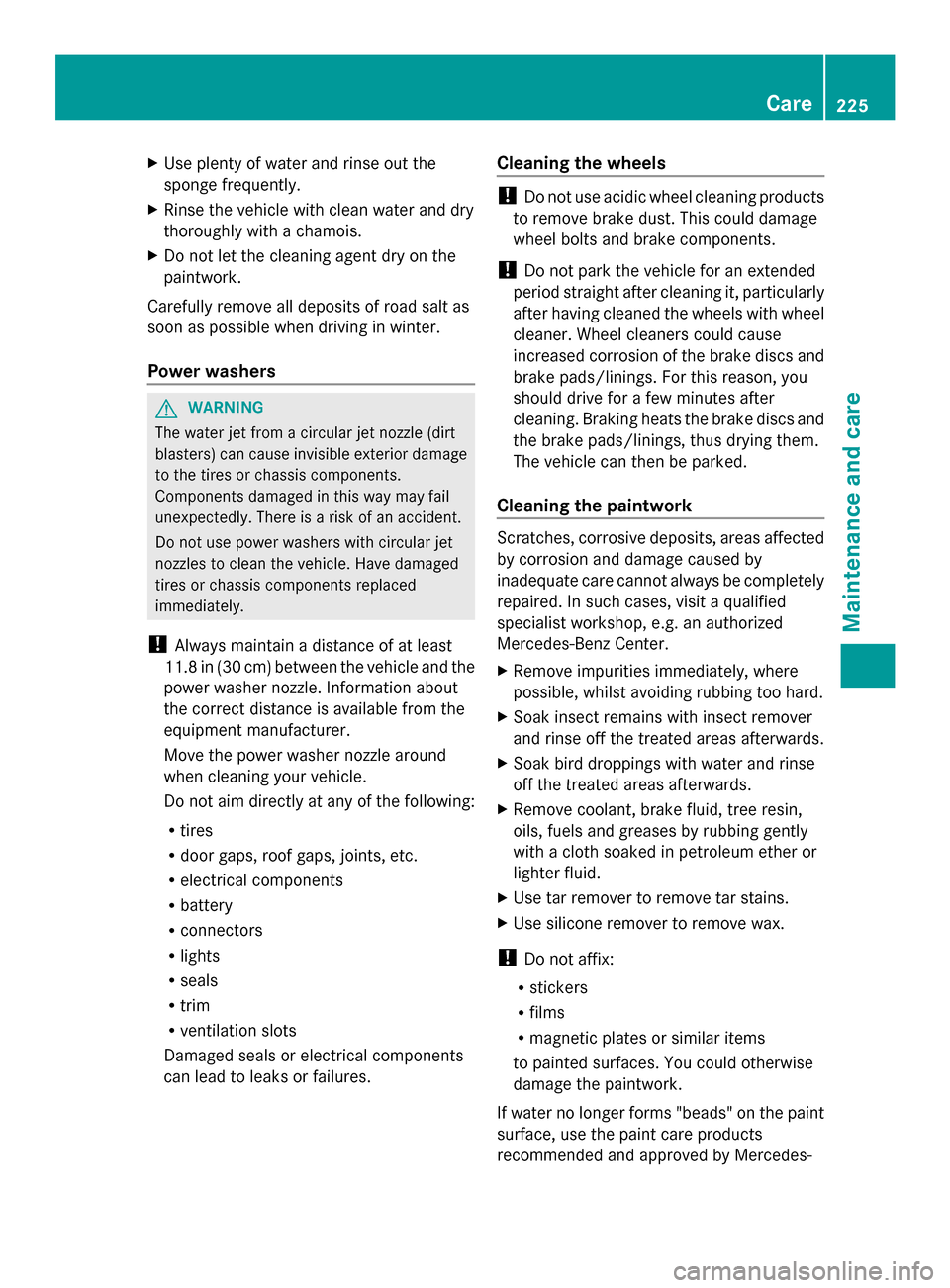
Power washers G
WARNING
The water jet from a circular jet nozzle (dirt
blasters) can cause invisible exterior damage
to the tires or chassis components.
Components damaged in this way may fail
unexpectedly. There is a risk of an accident.
Do not use power washers with circular jet
nozzles to clean the vehicle. Have damaged
tires or chassis components replaced
immediately.
! Always maintain a distance of at least
11.8 in (30 cm) between the vehicle and the
power washer nozzle. Information about
the correct distance is available from the
equipment manufacturer.
Move the power washer nozzle around
when cleaning your vehicle.
Do not aim directly at any of the following:
R tires
R door gaps, roof gaps, joints, etc.
R electrical components
R battery
R connectors
R lights
R seals
R trim
R ventilation slots
Damaged seals or electrical components
can lead to leaks or failures. Cleaning the wheels !
Do not use acidic wheel cleaning products
to remove brake dust. This could damage
wheel bolts and brake components.
! Do not park the vehicle for an extended
period straight after cleaning it, particularly
after having cleaned the wheels with wheel
cleaner. Wheel cleaners could cause
increased corrosion of the brake discs and
brake pads/linings. For this reason, you
should drive for a few minutes after
cleaning. Braking heats the brake discs and
the brake pads/linings, thus drying them.
The vehicle can then be parked.
Cleaning the paintwork Scratches, corrosive deposits, areas affected
by corrosion and damage caused by
inadequate care cannot always be completely
repaired. In such cases, visit a qualified
specialist workshop, e.g. an authorized
Mercedes-Benz Center.
X
Remove impurities immediately, where
possible, whilst avoiding rubbing too hard.
X Soak insect remains with insect remover
and rinse off the treated areas afterwards.
X Soak bird droppings with water and rinse
off the treated areas afterwards.
X Remove coolant, brake fluid, tree resin,
oils, fuels and greases by rubbing gently
with a cloth soaked in petroleum ether or
lighter fluid.
X Use tar remover to remove tar stains.
X Use silicone remover to remove wax.
! Do not affix:
R stickers
R films
R magnetic plates or similar items
to painted surfaces. You could otherwise
damage the paintwork.
If water no longer forms "beads" on the paint
surface, use the paint care products
recommended and approved by Mercedes- Care
225Maintenance and care Z
Page 257 of 290

drops in one or more of the tires. The tire
pressure monitor only functions if the correct
sensors are installed on all wheels.
Information on tire pressures is displayed in
the multifunction display. After a few minutes
of driving, the current tire pressure of each
tire is shown in the Service
Service menu of the
multifunction display. Example
For information on the message display, refer
to the "Checking the tire pressure
electronically" section (Y page 256).
Important safety notes G
WARNING
Each tire, including the spare (if provided),
should be checked at least once every two
weeks when cold and inflated to the pressure
recommended by the vehicle manufacturer
on the Tire and Loading Information placard
on the driver's door B-pillar or the tire
pressure label on the inside of the fuel filler
flap. If your vehicle has tires of a different size
than the size indicated on the Tire and Loading
Information placard or, if available, the tire
pressure label, you should determine the
proper tire pressure for those tires.
As an added safety feature, your vehicle has
been equipped with a tire pressure monitoring
system (TPMS) that illuminates a low tire
pressure telltale when one or more of your
tires are significantly underinflated.
Accordingly, when the low tire pressure
telltale lights up, you should stop and check
your tires as soon as possible, and inflate
them to the proper pressure. Driving on a
significantly underinflated tire causes the tire
to overheat and can lead to tire failure. Underinflation also reduces fuel efficiency
and tire tread life, and may affect the vehicle's
handling and stopping ability. Please note that
the TPMS is not a substitute for proper tire
maintenance, and it is the driver's
responsibility to maintain correct tire
pressure, even if underinflation has not
reached the level to trigger illumination of the
TPMS low tire pressure telltale.
Your vehicle has also been equipped with a
TPMS malfunction indicator to indicate when
the system is not operating properly. The
TPMS malfunction indicator is combined with
the low tire pressure telltale. When the
system detects a malfunction, the warning
lamp will flash for approximately a minute and
then remain continuously illuminated. This
sequence will be repeated every time the
vehicle is started as long as the malfunction
exists. When the malfunction indicator is
illuminated, the system may not be able to
detect or signal low tire pressure as intended.
TPMS malfunctions may occur for a variety of
reasons, including the installation of
incompatible replacement or alternate tires
or wheels on the vehicle that prevent the
TPMS from functioning properly. Always
check the TPMS malfunction telltale after
replacing one or more tires or wheels on your
vehicle to ensure that the replacement or
alternate Tires and wheels allow the TPMS to
continue to function properly.
It is the driver's responsibility to set the tire
pressure to that recommended for cold tires
which is suitable for the operating situation
(Y page 251). Note that the correct tire
pressure for the current operating situation
must first be taught-in to the tire pressure
monitor. If there is a substantial loss of
pressure, the warning threshold for the
warning message is aligned to the reference
values taught-in. Restart the tire pressure
monitor after adjusting the pressure of the
cold tires (Y page 257). The current
pressures are saved as new reference values. Tire pressure
255Wheels and tires Z