2014 MERCEDES-BENZ SLK ROADSTER tow bar
[x] Cancel search: tow barPage 95 of 357
Only fold AIRGUIDE in/out while the vehicle is
stationary.
! AIRGUIDE can only be positioned cor-
rectly by folding it in or out. AIRGUIDE can-
not be dismantled. Do not try to remove
AIRGUIDE from its anchorage. Otherwise,
you could damage AIRGUIDE or the vehicle.
AIRGUIDE can be folded out or back in from
the driver's side or passenger side.
When operating AIRGUIDE, preferably stand
on the side of the vehicle away from the traffic
after you have stopped the vehicle in accord- ance with road and traffic conditions.
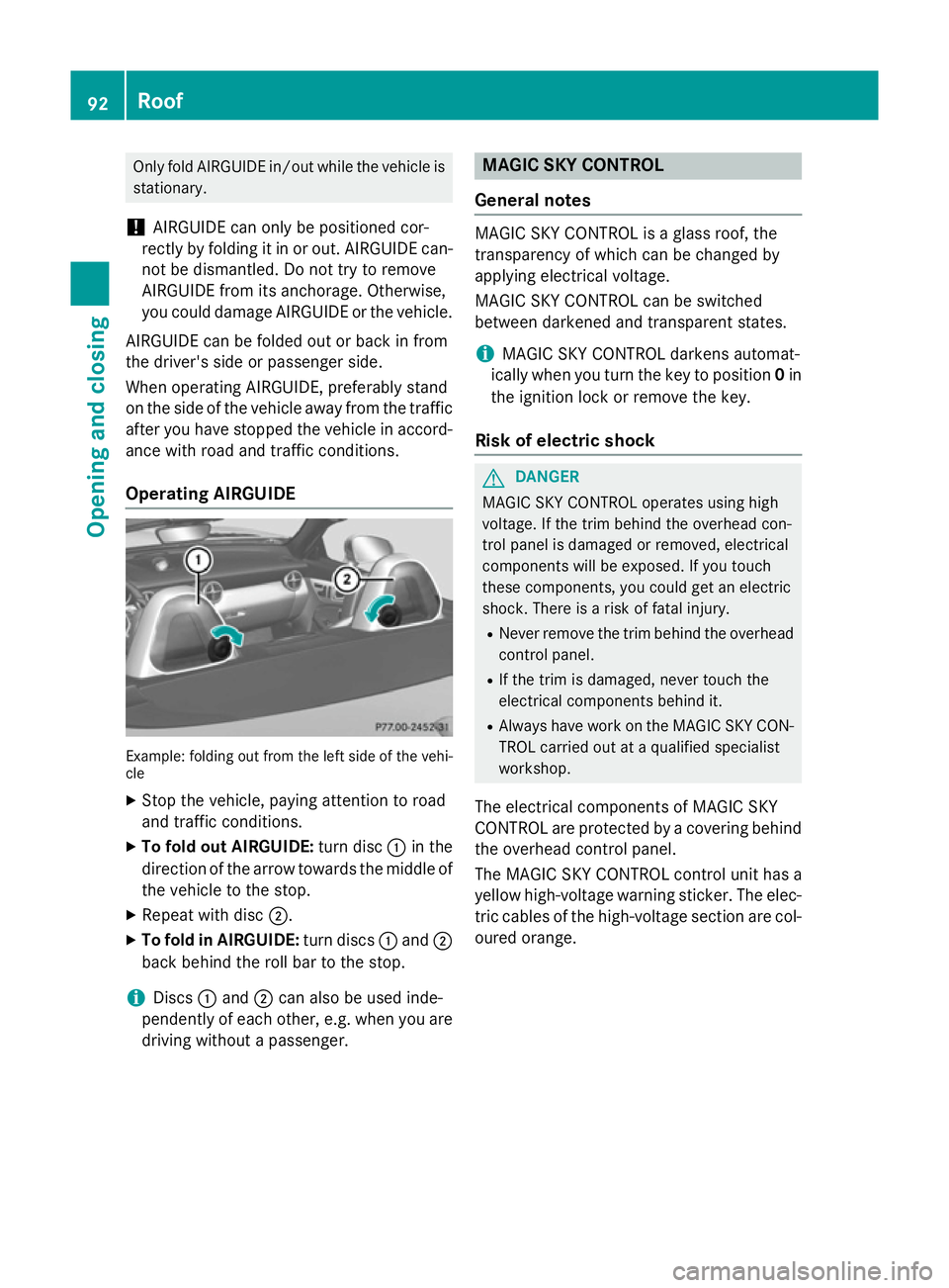
Operating AIRGUIDE Example: folding out from the left side of the vehi-
cle
X Stop the vehicle, paying attention to road
and traffic conditions.
X To fold out AIRGUIDE: turn disc:in the
direction of the arrow towards the middle of
the vehicle to the stop.
X Repeat with disc ;.
X To fold in AIRGUIDE: turn discs:and ;
back behind the roll bar to the stop.
i Discs
:and ;can also be used inde-
pendently of each other, e.g. when you are driving without a passenger. MAGIC SKY CONTROL
General notes MAGIC SKY CONTROL is a glass roof, the
transparency of which can be changed by
applying electrical voltage.
MAGIC SKY CONTROL can be switched
between darkened and transparent states.
i MAGIC SKY CONTROL darkens automat-
ically when you turn the key to position 0in
the ignition lock or remove the key.
Risk of electric shock G
DANGER
MAGIC SKY CONTROL operates using high
voltage. If the trim behind the overhead con-
trol panel is damaged or removed, electrical
components will be exposed. If you touch
these components, you could get an electric
shock. There is a risk of fatal injury.
R Never remove the trim behind the overhead
control panel.
R If the trim is damaged, never touch the
electrical components behind it.
R Always have work on the MAGIC SKY CON-
TROL carried out at a qualified specialist
workshop.
The electrical components of MAGIC SKY
CONTROL are protected by a covering behind the overhead control panel.
The MAGIC SKY CONTROL control unit has a
yellow high-voltage warning sticker. The elec-
tric cables of the high-voltage section are col- oured orange. 92
RoofOpening and closing
Page 103 of 357
AIRSCARF
Activating/deactivating G
WARNING
When AIRSCARF is switched on, very hot air
can flow from the vents in the head restraints. This could result in burns in the immediate
vicinity of the air vents. There is a risk of injury.
Reduce the heater output before it becomes
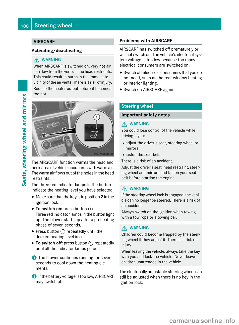
too hot. The AIRSCARF function warms the head and
neck area of vehicle occupants with warm air.
The warm air flows out of the holes in the head restraints.
The three red indicator lamps in the button
indicate the heating level you have selected.
X Make sure that the key is in position 2in the
ignition lock.
X To switch on: press button:.
Three red indicator lamps in the button light up. The blower starts up after a preheating
phase of seven seconds.
X Press button :repeatedly until the
desired heating level is set.
X To switch off: press button:repeatedly
until all the indicator lamps go out.
i The blower continues running for seven
seconds to cool down the heating ele-
ments.
i If the battery voltage is too low, AIRSCARF
may switch off. Problems with AIRSCARF AIRSCARF has switched off prematurely or
will not switch on. The vehicle's electrical sys-
tem voltage is too low because too many
electrical consumers are switched on.
X Switch off electrical consumers that you do
not need, such as the rear window heating
or interior lighting.
X Switch on AIRSCARF again. Steering wheel
Important safety notes
G
WARNING
You could lose control of the vehicle while
driving if you:
R adjust the driver's seat, steering wheel or
mirrors
R fasten the seat belt
There is a risk of an accident.
Adjust the driver's seat, head restraint, steer-
ing wheel and mirrors and fasten your seat
belt before starting the engine. G
WARNING
If the steering wheel lock is engaged, the vehi- cle can no longer be steered. There is a risk of
an accident.
Always switch on the ignition when towing
with a tow rope or a towing bar. G
WARNING
Children could become trapped by the steer-
ing wheel if they adjust it. There is a risk of
injury.
When leaving the vehicle, always take the key with you and lock the vehicle. Never leave
children unattended in the vehicle.
The electrically adjustable steering wheel can
still be adjusted when there is no key in the
ignition lock. 100
Steering wheelSeats
, steering wheel and mirrors
Page 192 of 357
Use Parking Guidance for parking spaces:
R that are parallel to the direction of travel
R that are on straight roads, not bends
R that are on the same level as the road, i.e.
not on the pavement, for example. Parking
Guidance may not detect flat kerbs
Parking tips:
R on narrow roads, drive as closely as possi-
ble past the parking space.
R parking spaces that are littered or over-
grown might be identified or measured
incorrectly.
R parking spaces that are partially occupied
by trailer drawbars might not be identified
as such or be measured incorrectly.
R snowfall or heavy rain may lead to a parking
space being measured inaccurately.
R pay attention to the PARKTRONIC
(Y page 186) warning messages during the
parking procedure.
R when transporting a load which protrudes
from your vehicle, you must not use Parking Guidance.
R never use Parking Guidance with snow
chains or an emergency spare wheel fitted.
R make sure that the tyre pressures are
always correct. This has a direct effect on
the steering instructions.
R the way your vehicle is positioned in the
parking space after parking is dependent
on various factors. These include the posi-
tion and shape of the vehicles parked in
front and behind it and the conditions of the
location. In some cases, Parking Guidance
may guide you too far or not far enough into
a parking space. In some cases, it may also lead you across or onto the kerb. If neces-
sary, cancel the parking procedure with
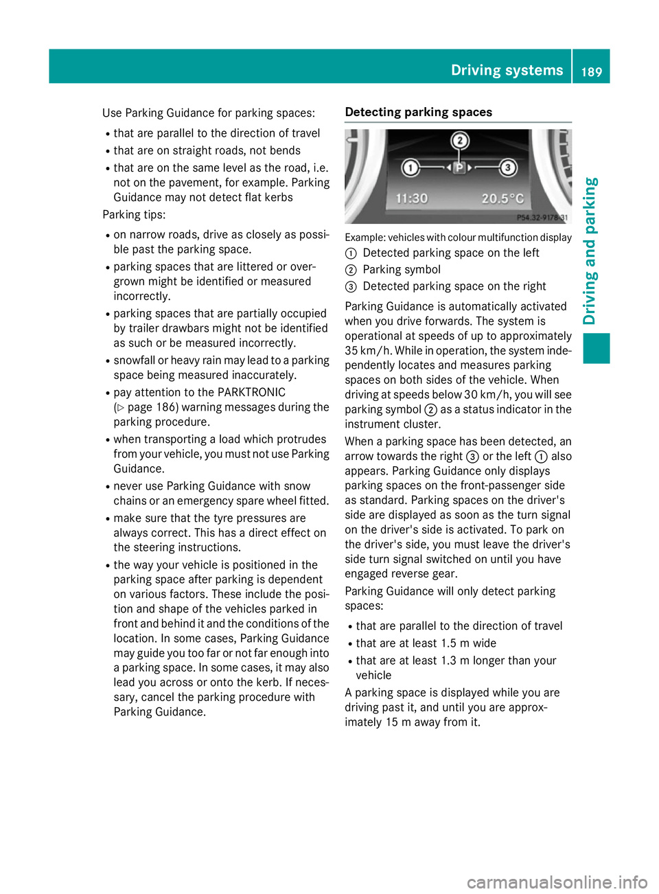
Parking Guidance. Detecting parking spaces Example: vehicles with colour multifunction display
: Detected parking space on the left
; Parking symbol
= Detected parking space on the right
Parking Guidance is automatically activated
when you drive forwards. The system is
operational at speeds of up to approximately 35 km/h. While in operation, the system inde- pendently locates and measures parking
spaces on both sides of the vehicle. When
driving at speeds below 30 km/h, you will see
parking symbol ;as a status indicator in the
instrument cluster.
When a parking space has been detected, an arrow towards the right =or the left :also
appears. Parking Guidance only displays
parking spaces on the front-passenger side
as standard. Parking spaces on the driver's
side are displayed as soon as the turn signal
on the driver's side is activated. To park on
the driver's side, you must leave the driver's
side turn signal switched on until you have
engaged reverse gear.
Parking Guidance will only detect parking
spaces:
R that are parallel to the direction of travel
R that are at least 1.5 m wide
R that are at least 1.3 m longer than your
vehicle
A parking space is displayed while you are
driving past it, and until you are approx-
imately 15 m away from it. Driving systems
189Driving and parking Z
Page 279 of 357
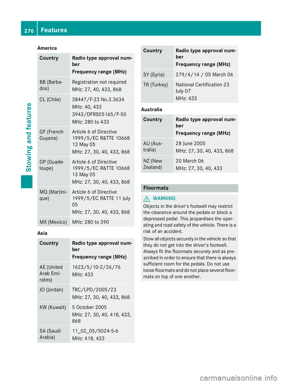
America
Country Radio type approval num-
ber
Frequency range (MHz)
BB (Barba-
dos) Registration not required
MHz: 27, 40, 433, 868
CL (Chile) 38447/F-23 No.3.3634
MHz: 40, 433
3943/DFRS05165/F-50
MHz: 280 to 433
GF (French
Guyana) Article 6 of Directive
1999/5/EC R&TTE 10668
13 May 05
MHz: 27, 30, 40, 433, 868
GP (Guade-
loupe) Article 6 of Directive
1999/5/EC R&TTE 10668
13 May 05
MHz: 27, 30, 40, 433, 868
MQ (Martini-
que) Article 6 of Directive
1999/5/EC R&TTE 11 July
05
MHz: 27, 30, 40, 433, 868
MX (Mexico) MHz: 280 to 390
Asia
Country Radio type approval num-
ber
Frequency range (MHz)
AE (United
Arab Emi-
rates) 1623/5/10-2/26/76
MHz: 433
JO (Jordan) TRC/LPD/2005/23
MHz: 27, 30, 40, 433, 868 KW (Kuwait) 5 October 2005
MHz: 27, 30, 40, 418, 433,
868
SA (Saudi
Arabia) 11_02_05/5024-5-6
MHz: 418, 433 Country Radio type approval num-
ber
Frequency range (MHz)
SY (Syria) 279/4/14 / 05 March 06
TR (Turkey) National Certification 23
July 07
MHz: 433
Australia
Country Radio type approval num-
ber
Frequency range (MHz)
AU (Aus-
tralia) 28 June 2005
MHz: 27, 30, 40, 433, 868
NZ (New
Zealand) 20 March 06
MHz: 27, 30, 40, 433
Floormats
G
WARNING
Objects in the driver's footwell may restrict
the clearance around the pedals or block a
depressed pedal. This jeopardises the oper-
ating and road safety of the vehicle. There is a risk of an accident.
Stow all objects securely in the vehicle so that
they do not get into the driver's footwell.
Always fit the floormats securely and as pre-
scribed in order to ensure that there is always sufficient room for the pedals. Do not use
loose floormats and do not place several floor-mats on top of one another. 276
FeaturesStowing and featu
res
Page 302 of 357
X
Insert plug =into the socket of the ciga-
rette lighter (Y page 268) or into a 12 V
power socket in your vehicle (Y page 269).
X Turn the key to position 1(Y page 141) in
the ignition lock.
X Press on/off switch ?on the tyre inflation
compressor to ON.
The tyre inflation compressor is switched
on. The tyre is inflated.
i First, tyre sealant is pumped into the tyre.
The pressure may briefly rise to approx-
imately 500 kPa (5 bar/73 psi).
Do not switch off the tyre inflation com-
pressor during this phase.
X Let the tyre inflation compressor run for a
maximum of ten minutes. The tyre should
then have attained a pressure of at least
200 kPa (2.0 bar/29 psi).
If a tyre pressure of 200 kPa (2.0 bar/29 psi)
has been achieved after ten minutes
(Y page 299).
If a tyre pressure of 200 kPa (2.0 bar/29 psi)
has not been achieved after ten minutes
(Y page 299).
i If the tyre sealant leaks out, allow it to dry.
It can then be removed like a layer of film.
If you get tyre sealant on your clothing,
have it cleaned as soon as possible with
perchloroethylene.
Tyre pressure not reached If a tyre pressure of 200 kPa (2.0 bar/29 psi)
has not been achieved after ten minutes:
X Switch off the tyre inflation compressor.
X Unscrew the filler hose from the valve of
the faulty tyre.
X Very slowly drive forwards or reverse,
approximately 10 m.
X Pump up the tyre again.
After a maximum of ten minutes, the tyre
pressure must be at least 200 kPa (2.0 bar/ 29 psi). G
WARNING
If the required tyre pressure is not reached
after the specified time, the tyre is too badly
damaged. The tyre sealant cannot repair the
tyre in this instance. Damaged tyres and a tyre pressure that is too low can significantly
impair the vehicle's braking and driving char-
acteristics. There is a risk of accident.
Do not continue driving. Contact a qualified
specialist workshop.
Tyre pressure reached G
WARNING
A tyre temporarily sealed with tyre sealant
impairs the driving characteristics and is not
suitable for higher speeds. There is a risk of
accident.
You should therefore adapt your driving style
accordingly and drive carefully. Do not exceed the specified maximum speed with a tyre that
has been repaired using tyre sealant.
! After use, excess tyre sealant may run out
of the filler hose. This could cause stains.
Therefore, place the filler hose in the plastic
bag which contained the TIREFIT kit. H
Environmental note
Have the used tyre sealant bottle disposed of professionally, e.g. at a qualified specialist
workshop.
If a tyre pressure of 200 kPa (2.0 bar/29 psi) has been achieved after ten minutes:
X Switch off the tyre inflation compressor.
X Unscrew the filler hose from the valve of
the faulty tyre.
X Stow the tyre sealant bottle, the tyre infla-
tion compressor and the warning triangle.
X Pull away immediately.
The maximum speed for a tyre sealed with
tyre sealant is 80 km/h. The upper part of
the TIREFIT sticker must be affixed to the Flat tyre
299Breakdown assistance Z
Page 303 of 357
instrument cluster where it will be easily
seen by the driver.
X Stop after driving for approximately ten
minutes and check the tyre pressure with
the tyre inflation compressor.
The tyre pressure must now be at least
130 kPa (1.3 bar/19 psi). G
WARNING
If the required tyre pressure is not reached
after driving for a short period, the tyre is too badly damaged. The tyre sealant cannot
repair the tyre in this instance. Damaged tyres and a tyre pressure that is too low can signif-
icantly impair the vehicle's braking and driv-
ing characteristics. There is a risk of accident.
Do not continue driving. Contact a qualified
specialist workshop.
i In your vehicle, you will find a sticker with
the Mercedes-Benz Service24h telephone
number, e.g. on the B-pillar on the driver's
side.
X Correct the tyre pressure if it is still at least
130 kPa (1.3 bar/19 psi) (see the fuel filler
flap for values).
X To increase the tyre pressure: switch on
the tyre inflation compressor. X
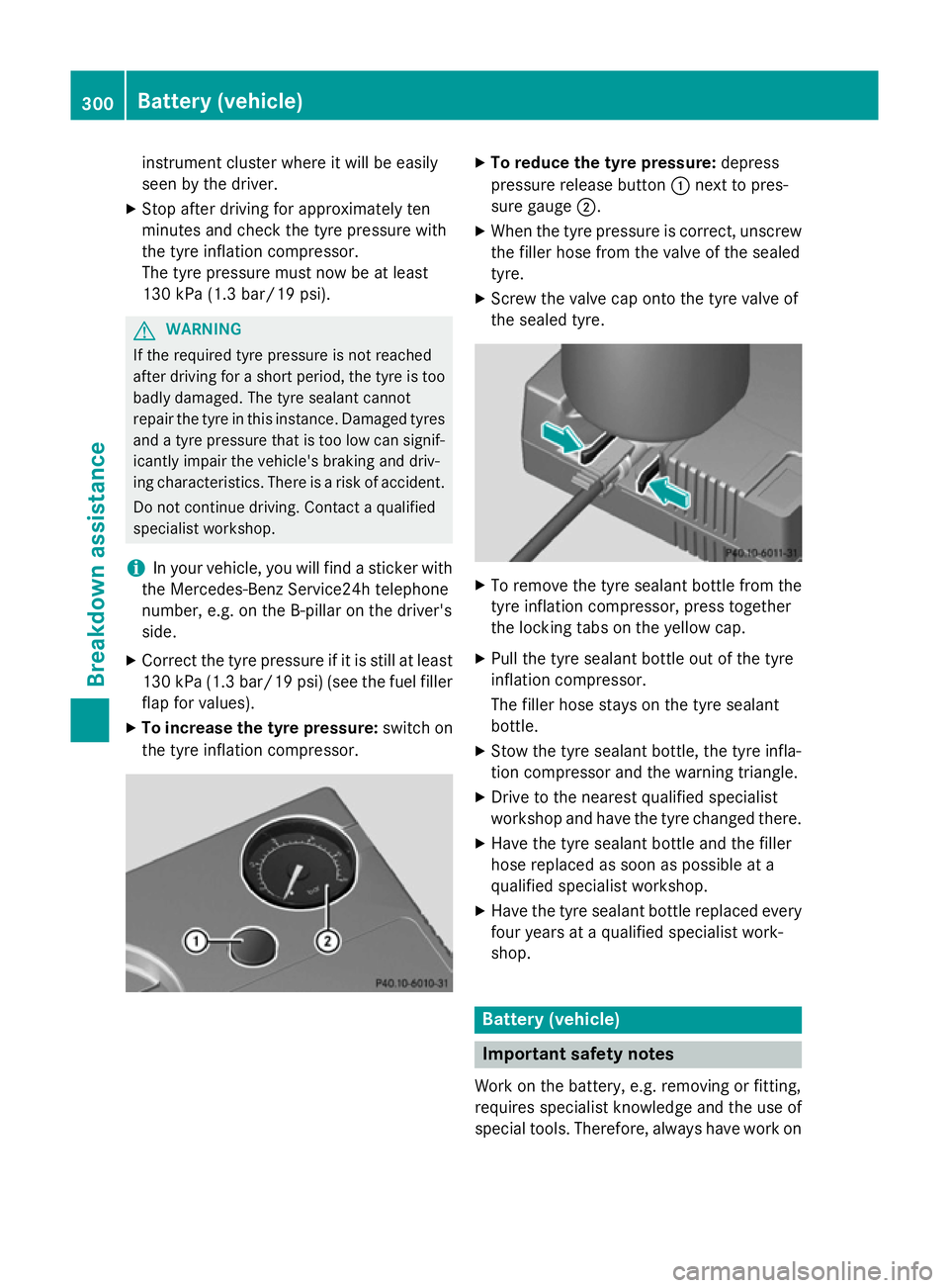
To reduce the tyre pressure: depress
pressure release button :next to pres-
sure gauge ;.
X When the tyre pressure is correct, unscrew
the filler hose from the valve of the sealed
tyre.
X Screw the valve cap onto the tyre valve of
the sealed tyre. X
To remove the tyre sealant bottle from the
tyre inflation compressor, press together
the locking tabs on the yellow cap.
X Pull the tyre sealant bottle out of the tyre
inflation compressor.
The filler hose stays on the tyre sealant
bottle.
X Stow the tyre sealant bottle, the tyre infla-
tion compressor and the warning triangle.
X Drive to the nearest qualified specialist
workshop and have the tyre changed there.
X Have the tyre sealant bottle and the filler
hose replaced as soon as possible at a
qualified specialist workshop.
X Have the tyre sealant bottle replaced every
four years at a qualified specialist work-
shop. Battery (vehicle)
Important safety notes
Work on the battery, e.g. removing or fitting,
requires specialist knowledge and the use of
special tools. Therefore, always have work on 300
Battery (vehicle)Breakdown assistance
Page 309 of 357
Position number
Bidentifies the charged battery of the other vehicle or an equivalent jump-
starting device.
X Slide cover :of positive terminal ;in the direction of the arrow.
X Connect positive terminal ;on your vehicle to positive terminal =of donor battery B
using the jump lead. Always begin with positive terminal ;on your own vehicle first.
X Start the engine of the donor vehicle and run it at idling speed.
X Connect negative terminal ?of donor battery Bto earth point Aof your vehicle using the
jump lead, connecting the jump lead to donor battery Bfirst.
X Start the engine.
X Before disconnecting the jump leads, let the engines run for several minutes.
X First, remove the jump leads from earth point Aand negative terminal ?, then from pos-
itive clamp ;and positive terminal =. Begin each time at the contacts on your own vehicle
first.
X Close cover :of positive terminal ;after removing the jump leads.
X Have the battery checked at a qualified specialist workshop.
i Jump-starting is not considered to be a normal operating condition.
i Jump-starting cables and further information regarding jump starting can be obtained at
any qualified specialist workshop. Towing and tow-starting
Important safety notes
! Do not tow-start vehicles with automatic
transmission. You could otherwise damage the automatic transmission. G
WARNING
If the weight of the vehicle to be towed or tow- started is greater than the permissible gross
weight of your vehicle:
R the towing eye could detach itself
R the vehicle/trailer combination could over-
turn.
There is a risk of an accident.
When towing or tow-starting another vehicle,
its weight should not be greater than the per-
missible gross weight of your vehicle. !
If DISTRONIC PLUS or the HOLD function
is activated, the vehicle brakes automati-
cally in certain situations. To prevent dam-
age to the vehicle, deactivate DISTRONIC
PLUS and the HOLD function in the follow- ing or other similar situations:
R when towing the vehicle
R in the car wash
! Only secure the tow rope or towing bar to
the towing eyes. The vehicle may otherwise be damaged.
! Observe the following points when towing
with a tow rope:
R secure the tow rope on the same side on
both vehicles.
R make sure that the tow rope is not longer
than legally permitted. Mark the tow rope in the middle, e.g. with a white cloth
(30 x 30 cm). This makes other road
users aware that a vehicle is being
towed.
R only secure the tow rope to the towing
eye. 306
Towing and tow-startingBreakdown assistance
Page 311 of 357
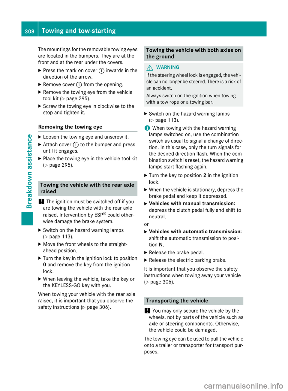
The mountings for the removable towing eyes
are located in the bumpers. They are at the
front and at the rear under the covers.
X Press the mark on cover :inwards in the
direction of the arrow.
X Remove cover :from the opening.
X Remove the towing eye from the vehicle
tool kit (Y page 295).
X Screw the towing eye in clockwise to the
stop and tighten it.
Removing the towing eye X
Loosen the towing eye and unscrew it.
X Attach cover :to the bumper and press
until it engages.
X Place the towing eye in the vehicle tool kit
(Y page 295). Towing the vehicle with the rear axle
raised
! The ignition must be switched off if you
are towing the vehicle with the rear axle
raised. Intervention by ESP ®
could other-
wise damage the brake system.
X Switch on the hazard warning lamps
(Y page 113).
X Move the front wheels to the straight-
ahead position.
X Turn the key in the ignition lock to position
0 and remove the key from the ignition
lock.
X When leaving the vehicle, take the key or
the KEYLESS-GO key with you.
When towing your vehicle with the rear axle
raised, it is important that you observe the
safety instructions (Y page 306). Towing the vehicle with both axles on
the ground G
WARNING
If the steering wheel lock is engaged, the vehi- cle can no longer be steered. There is a risk of
an accident.
Always switch on the ignition when towing
with a tow rope or a towing bar.
X Switch on the hazard warning lamps
(Y page 113).
i When towing with the hazard warning
lamps switched on, use the combination
switch as usual to signal a change of direc- tion. In this case, only the turn signals for
the desired direction flash. When the com- bination switch is reset, the hazard warning lamps start flashing again.
X Turn the key to position 2in the ignition
lock.
X When the vehicle is stationary, depress the
brake pedal and keep it depressed.
X Vehicles with manual transmission:
depress the clutch pedal fully and shift to
neutral.
or
X Vehicles with automatic transmission:
shift the automatic transmission to posi-
tion N.
X Release the brake pedal.
X Release the electric parking brake.
It is important that you observe the safety
instructions when towing away your vehicle
(Y page 306). Transporting the vehicle
! You may only secure the vehicle by the
wheels, not by parts of the vehicle such as
axle or steering components. Otherwise,
the vehicle could be damaged.
The towing eye can be used to pull the vehicle
onto a trailer or transporter for transport pur-
poses. 308
Towing and tow-startingBreakdown assistance