2014 MERCEDES-BENZ SL-CLASS ROADSTER tow bar
[x] Cancel search: tow barPage 20 of 284

Tire pressure
Calling up (on-board computer) .....250
Checking manually ........................249
Display message ............................ 174
Important safety notes ..................250
Maximum ....................................... 249
Notes ............................................. 248
Not reached (TIREFIT) ....................230
Reached (TIREFIT) ..........................230
Recommended ............................... 246
Tire pressure monitoring system
Checking the tire pressure
electronically ................................. 251
Function/notes ............................. 250
General notes ................................ 250
Important safety notes ..................250
Restarting ...................................... 252
Warning lamp ................................. 185
Warning message .......................... 252
Tires
Aspect ratio (definition) .................262
Average weight of the vehicle
occupants (definition) ....................261
Bar (definition) ............................... 261
Changing a wheel .......................... 263
Characteristics .............................. 260
Checking ........................................ 245
Definition of terms .........................261
Direction of rotatio n...................... 263
Display message ............................ 174
Distribution of the vehicle
occupants (definition) ....................263
DOT, Tire Identification Number
(TIN) .............................................. .260
DOT (Department of
Transportation) (definition) ............261
GAWR (Gross Axle Weight Rating)
(definition) ..................................... 261
GVW (Gross Vehicle Weight)
(definition) ..................................... 261
GVWR (Gross Vehicle Weight
Rating) (definition) .........................261
Important safety notes ..................244
Increased vehicle weight due to
optional equipment (definition) ......261
Kilopascal (kPa) (definition) ...........262
Labeling (overview )........................ 257
Load bearing index (definition) ......263 Load index
..................................... 259
Load index (definition) ...................262
Maximum loaded vehicle weight
(definition) ..................................... 262
Maximum load on a tire (definition) 262
Maximum permissible tire
pressure (definition) ....................... 262
Maximum tire loa d......................... 260
Maximum tire load (definition) .......262
MOExtended tires ..........................246
Optional equipment weight
(definition) ..................................... 262
Overview ........................................ 244
PSI (pounds per square inch)
(definition) ..................................... 262
Replacing ....................................... 263
Service life ..................................... 246
Sidewall (definition) .......................262
Speed rating (definition) ................261
Storing ........................................... 264
Structure and characteristics
(definition) ..................................... 261
Temperature .................................. 256
TIN (Tire Identification Number)
(definition) ..................................... 262
Tire bead (definition) ......................262
Tire pressure (definition) ................262
Tire pressures (recommended )...... 261
Tire size (data) ............................... 268
Tire size designation, load-bearing
capacity, speed rating .................... 257
Tire tread ....................................... 245
Tire tread (definition) .....................262
Total load limit (definition) .............263
Traction ......................................... 256
Traction (definition) .......................263
Tread wea r..................................... 256
Uniform Tire Quality Grading
Standards ...................................... 255
Uniform Tire Quality Grading
Standards (definition) ....................261
Unladen weight (definition) ............262
Wear indicator (definition) .............263
Wheel rim (definition) ....................261
see Flat tire
Towing
Important safety guidelines ...........237
Installing the towing eye ................23818
Index
Page 53 of 284

deployment thresholds for lateral
acceleration/deceleration. You will then be
protected by the fastened seat belt.
The head bag on the front-passenger side is
not deployed in the following situations:
R the OCS system detects that the front-
passenger seat is not occupied, and
R the front-passenger seat belt is not
fastened.
The head bag on the front-passenger side will
deploy if the front-passenger seat belt is
fastened, regardless of whether the front-
passenger seat is occupied or not. Roll bar
G
DANGER
If the roll bar has developed a malfunction, it
may not function, e.g. in the event of an
accident. The roll bars may then not protect
the vehicle occupants as intended. This poses
an increased risk of injury or even fatal injury.
Have roll bars checked immediately at a
qualified specialist workshop. G
WARNING
If you place objects or clothing on the roll bar
covers, these could impair roll bar extension.
The roll bars may then not protect the vehicle
occupants as intended. In addition, objects
could endanger the vehicle occupants when
the roll bar is extending. This poses an
increased risk of injury or even fatal injury.
Ensure that the movement area of the roll bar
covers is kept clear. Always stow all objects
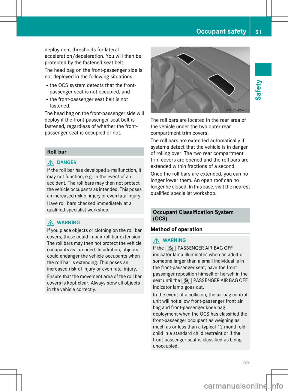
in the vehicle correctly. The roll bars are located in the rear area of
the vehicle under the two outer rear
compartment trim covers.
The roll bars are extended automatically if
systems detect that the vehicle is in danger
of rolling over. The two rear compartment
trim covers are opened and the roll bars are
extended within fractions of a second.
Once the roll bars are extended, you can no
longer lower them. An open roof can no
longer be closed. In this case, visit the nearest
qualified specialist workshop.
Occupant Classification System
(OCS)
Method of operation G
WARNING
If the 4 PASSENGER AIR BAG OFF
indicator lamp illuminates when an adult or
someone larger than a small individual is in
the front-passenger seat, have the front
passenger reposition himself or herself in the
seat until the 4PASSENGER AIR BAG OFF
indicator lamp goes out.
In the event of a collision, the air bag control
unit will not allow front-passenger front air
bag and front-passenger knee bag
deployment when the OCS has classified the
front-passenger occupant as weighing as
much as or less than a typical 12 month old
child in a standard child restraint or if the
front-passenger seat is classified as being
unoccupied. Occupant safety
51Safety
Z
Page 104 of 284

Therefore, do not switch the seat heating on
repeatedly. Driver's and front-passenger seat
The three red indicator lamps in the button
indicate the heating level you have selected.
The system automatically switches down
from level 3to level 2after approximately
eight minutes.
The system automatically switches down
from level 2to level 1after approximately ten
minutes.
The system automatically switches off
approximately 20 minutes after it is set to
level 1.
You can set the distribution of the heated
sections of the seat cushion and backrest
using COMAND. See Digital Operator's
Manual; keyword "Seat balance (seat
heating)".
X Make sure that the SmartKey is in position
1or 2in the ignition lock.
X To switch on: press button:repeatedly
until the desired heating level is set.
X To switch off: press button:repeatedly
until all the indicator lamps go out.
i If the battery voltage is too low, the seat
heating may switch off.
Problems with the seat heating You can find information about this in the
Digital Operator's Manual. Steering wheel
Important safety notes
G
WARNING
You could lose control of your vehicle if you
do the following while driving:
R adjust the driver's seat, head restraint,
steering wheel or mirrors
R fasten the seat belt
There is a risk of an accident.
Adjust the driver's seat, head restraint,
steering wheel and mirror and fasten your
seat belt before starting the engine. G
WARNING
You can no longer steer the vehicle if the
steering wheel lock has been engaged. There
is a risk of an accident.
Always switch off the ignition when towing the
vehicle with a tow cable or a tow bar. Information in the Digital Operator's
Manual
In the Digital Operator's Manual you will find
information on the following topics:
R Adjusting the steering wheel
R EASY-ENTRY/EXIT system Mirrors
In the Digital Operator's Manual you will find
information on the following topics:
R Exterior mirrors
R Automatic anti-glare mirrors
R Parking position for the exterior mirror on
the front-passenger side 102
MirrorsSeats, steering wheel and mirrors
Page 149 of 284

Rear view camera
General notes Rear view camera
:is in the trunk lid handle.
Rear view camera :is an optical parking and
maneuvering aid. It shows the area behind
your vehicle with guide lines in the COMAND
display.
The area behind the vehicle is displayed as a
mirror image, as in the rear view mirror.
i The text of messages shown in the
COMAND display depends on the language
setting. The following are examples of rear
view camera messages in the COMAND
display.
Important safety notes The rear view camera is only an aid. It is not
a replacement for your attention to your
immediate surroundings. You are always
responsible for safe maneuvering and
parking. When maneuvering or parking, make
sure that there are no persons, animals or
objects in the area in which you are
maneuvering.
Under the following circumstances, the rear
view camera will not function, or will function
in a limited manner:
R the tailgate is open
R in heavy rain, snow or fog
R at night or in very dark places
R if the camera is exposed to very bright light R
if the area is lit by fluorescent light or LED
lighting (the display may flicker)
R if there is a sudden change in temperature,
e.g. when driving into a heated garage in
winter
R if the camera lens is dirty or obstructed
R if the rear of your vehicle is damaged. In
this event, have the camera position and
setting checked at a qualified specialist
workshop
The field of vision and other functions of the
rear view camera may be restricted due to
additional accessories on the rear of the
vehicle (e.g. license plate holder, bicycle
rack).
! Objects not at ground level may appear to
be further away than they actually are, e.g.:
R the bumper of a parked vehicle
R the drawbar of a trailer
R the ball coupling of a trailer tow hitch
R the rear section of an HGV
R a slanted post
Use the guidelines only for orientation.
Approach objects no further than the
bottom-most guideline.
The rear view camera may show a distorted
view of obstacles, show them incorrectly or
not at all. The rear view camera does not show
objects in the following positions:
R very close to the rear bumper
R under the rear bumper
R in close range above the handle on the
trunk lid Driving systems
147Driving and parking Z
Page 232 of 284

X
Press on/off switch =on the tire inflation
compressor to I.
The tire inflation compressor is switched
on. The tire is inflated.
i First, tire sealant is pumped into the tire.
The pressure can briefly rise to
approximately 500 kPa (5.0 bar/73 psi).
Do not switch off the tire inflation
compressor during this phase.
X Allow the tire inflation compressor to run
for five minutes. The tire should then have
attained a pressure of at least 180 kPa
(1.8 bar/26 psi).
If a tire pressure of 180 kPa (1.8 ba r/26 psi)
has been attained after five minutes:
(Y page 230).
If a tire pressure of 180 kPa (1.8 ba r/26 psi)
has not been attained after five minutes:
(Y page 230).
i If tire sealant leaks out, allow it to dry. It
can then be removed like a layer of film.
If your clothes are soiled with tire sealant,
have them cleaned with perchloroethylene
at a dry cleaner as soon as possible.
Tire pressure not reached If a tire pressure of 180 kPa
(1.8 ba r/26 psi)
has not been attained after five minutes:
X Switch off the tire inflation compressor.
X Unscrew the filler hose from the valve of
the faulty tire.
X Very slowly drive forwards or reverse
approximately 30 ft (10 m).
X Pump up the tire again.
After a maximum of five minutes the tire
pressure must be at least 180 kPa (1.8 bar/
26 psi). G
WARNING
If the required tire pressure is not reached
after the specified time, the tire is too badly
damaged. The tire sealant cannot repair the
tire in this instance. Damaged tires and a tire
pressure that is too low can significantly impair the vehicle's braking and driving
characteristics. There is a risk of accident.
Do not continue driving. Contact a qualified
specialist workshop.
Tire pressure reached G
WARNING
A tire temporarily sealed with tire sealant
impairs the driving characteristics and is not
suitable for higher speeds. There is a risk of
accident.
You should therefore adapt your driving style
accordingly and drive carefully. Do not exceed
the specified maximum speed with a tire that
has been repaired using tire sealant.
! Residue from the tire sealant may come
out of the filler hose after use. This could
cause stains.
Therefore, place the filler hose in the plastic
bag which contained the TIREFIT kit. H
Environmental note
Have the used tire sealant bottle disposed of
professionally, e.g. at a qualified specialist
workshop.
If a tire pressure of 180 kPa (1.8 ba r/26 psi)
has been achieved after a maximum period of
ten minutes:
X Switch off the tire inflation compressor.
X Unscrew the filler hose from the valve of
the faulty tire.
X Stow the tire sealant bottle and the tire
inflation compressor.
X Pull away immediately.
The maximum speed for a tire sealed with
tire sealant is 50 mph (80 km/h). The upper
part of the TIREFIT sticker must be affixed 230
Flat tireBreakdown assistance
Page 233 of 284

to the instrument cluster in the driver's
field of vision.
X Stop after driving for approximately ten
minutes and check the tire pressure with
the tire inflation compressor.
The tire pressure must now be at least
130 kPa (1.3 bar/19 psi). G
WARNING
If the required tire pressure is not reached
after driving for a short period, the tire is too
badly damaged. The tire sealant cannot repair
the tire in this instance. Damaged tires and a
tire pressure that is too low can significantly
impair the vehicle's braking and driving
characteristics. There is a risk of accident.
Do not continue driving. Contact a qualified
specialist workshop.
X Correct the tire pressure if it is still at least
130 kPa (1.3 bar/19 psi) (for the values,
see the Tire and Loading Information
placard on the driver's side B-pillar or tire
pressure table on the fuel filler flap).
X To increase the tire pressure: switch on
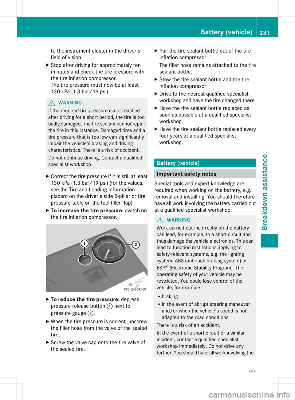
the tire inflation compressor. X
To reduce the tire pressure: depress
pressure release button :next to
pressure gauge ;.
X When the tire pressure is correct, unscrew
the filler hose from the valve of the sealed
tire.
X Screw the valve cap onto the tire valve of
the sealed tire. X
Pull the tire sealant bottle out of the tire
inflation compressor.
The filler hose remains attached to the tire
sealant bottle.
X Stow the tire sealant bottle and the tire
inflation compressor.
X Drive to the nearest qualified specialist
workshop and have the tire changed there.
X Have the tire sealant bottle replaced as
soon as possible at a qualified specialist
workshop.
X Have the tire sealant bottle replaced every
four years at a qualified specialist
workshop. Battery (vehicle)
Important safety notes
Special tools and expert knowledge are
required when working on the battery, e.g.
removal and installing. You should therefore
have all work involving the battery carried out
at a qualified specialist workshop. G
WARNING
Work carried out incorrectly on the battery
can lead, for example, to a short circuit and
thus damage the vehicle electronics. This can
lead to function restrictions applying to
safety-relevant systems, e.g. the lighting
system, ABS (anti-lock braking system) or
ESP ®
(Electronic Stability Program). The
operating safety of your vehicle may be
restricted. You could lose control of the
vehicle, for example:
R braking
R in the event of abrupt steering maneuver
and/or when the vehicle's speed is not
adapted to the road conditions
There is a risk of an accident.
In the event of a short circuit or a similar
incident, contact a qualified specialist
workshop immediately. Do not drive any
further. You should have all work involving the Battery (vehicle)
231Breakdown assistance
Z
Page 239 of 284

Position number
Bidentifies the charged battery of the other vehicle or an equivalent jump-
starting device.
X Press cover :of positive terminal ;down (in the direction of the arrow) and turn it
clockwise. Cover :is held down in the lowered position, which exposes positive
terminal ;.
X Connect positive terminal ;on your vehicle to positive terminal =of donor battery B
using the jumper cable, always begin with positive terminal ;on your own vehicle first.
X Start the engine of the donor vehicle and run it at idling speed.
X Connect negative terminal ?of donor battery Bto ground point Aof your vehicle using
the jumper cable, connecting the jumper cable to battery of other vehicle Bfirst.
X Start the engine.
X Before disconnecting the jumper cables, let the engine run for several minutes.
X First, remove the jumper cables from ground point Aand negative terminal ?, then from
positive clamp ;and positive terminal =. Begin each time at the contacts on your own
vehicle first.
X After removing the jumper cables, press down cover :of positive terminal ;and turn it
counter-clockwise. Cover :returns to its original position. Positive terminal ;is covered
up and thus insulated again.
X Have the battery checked at a qualified specialist workshop.
i Jump-starting is not considered to be a normal operating condition.
i Jumper cables and further information regarding jump-starting can be obtained at any
qualified specialist workshop. Towing and tow-starting
Important safety notes
G
WARNING
If the weight of the vehicle to be towed or tow-
started is greater than the permissible gross
weight of your vehicle:
R the towing eye could detach itself
R the vehicle/trailer combination could
rollover.
There is a risk of an accident.
When towing or tow-starting another vehicle,
its weight should not be greater than the
permissible gross weight of your vehicle. !
If DISTRONIC PLUS or the HOLD function
is activated, the vehicle brakes
automatically in certain situations. To
prevent damage to the vehicle, deactivate
DISTRONIC PLUS and the HOLD function in
the following or other similar situations:
R when towing the vehicle
R in the car wash
! Only secure the tow rope or tow bar at the
towing eyes. Otherwise, the vehicle could
be damaged.
! Do not use the towing eye for recovery,
this could damage the vehicle. If in doubt,
recover the vehicle with a crane.
! When towing, pull away slowly and
smoothly. If the tractive power is too high,
the vehicles could be damaged. Towing and tow-starting
237Breakdown assistance Z
Page 241 of 284

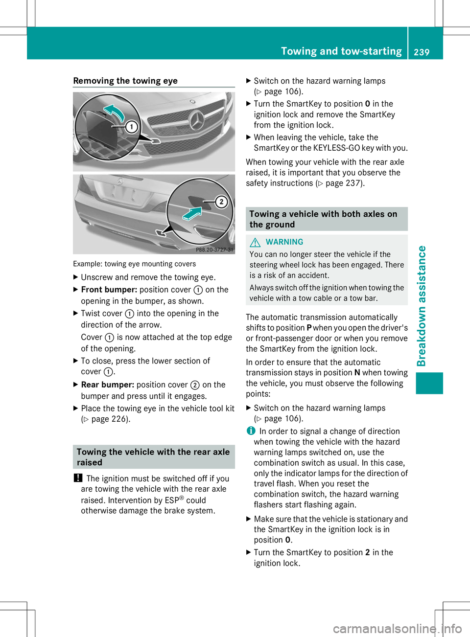
Removing the towing eye
Example: towing eye mounting covers
X
Unscrew and remove the towing eye.
X Front bumper: position cover:on the
opening in the bumper, as shown.
X Twist cover :into the opening in the
direction of the arrow.
Cover :is now attached at the top edge
of the opening.
X To close, press the lower section of
cover :.
X Rear bumper: position cover;on the
bumper and press until it engages.
X Place the towing eye in the vehicle tool kit
(Y page 226). Towing the vehicle with the rear axle
raised
! The ignition must be switched off if you
are towing the vehicle with the rear axle
raised. Intervention by ESP ®
could
otherwise damage the brake system. X
Switch on the hazard warning lamps
(Y page 106).
X Turn the SmartKey to position 0in the
ignition lock and remove the SmartKey
from the ignition lock.
X When leaving the vehicle, take the
SmartKey or the KEYLESS-GO key with you.
When towing your vehicle with the rear axle
raised, it is important that you observe the
safety instructions (Y page 237). Towing a vehicle with both axles on
the ground
G
WARNING
You can no longer steer the vehicle if the
steering wheel lock has been engaged. There
is a risk of an accident.
Always switch off the ignition when towing the
vehicle with a tow cable or a tow bar.
The automatic transmission automatically
shifts to position Pwhen you open the driver's
or front-passenger door or when you remove
the SmartKey from the ignition lock.
In order to ensure that the automatic
transmission stays in position Nwhen towing
the vehicle, you must observe the following
points:
X Switch on the hazard warning lamps
(Y page 106).
i In order to signal a change of direction
when towing the vehicle with the hazard
warning lamps switched on, use the
combination switch as usual. In this case,
only the indicator lamps for the direction of
travel flash. When you reset the
combination switch, the hazard warning
flashers start flashing again.
X Make sure that the vehicle is stationary and
the SmartKey in the ignition lock is in
position 0.
X Turn the SmartKey to position 2in the
ignition lock. Towing and tow-starting
239Breakdown assistance Z