2014 MERCEDES-BENZ S-Class light
[x] Cancel search: lightPage 332 of 434
!
Note that work and repairs on the 115 V
power socket should only be carried out by
qualified specialist personnel.
General notes The 115 V power socket provides an
alternating voltage of 115 V so that small
electronic devices can be connected. These
devices, such as games consoles, chargers
and laptops, must not consume more than a
maximum of 150 watts altogether.
Requirements for operation of these devices:
R the electronic device that you connect has
a suitable connector and conforms to
standards specific to the country you are
in.
R the plug of the electronic device is plugged
correctly into 115 V power socket.
R the maximum wattage of the device to be
connected must not exceed 150 watts.
R the on-board power supply is within a
permissible voltage range.
R the 12 V sockets in the center console in
the front compartment (Y page 328) and in
the trunk are functional (Y page 329).
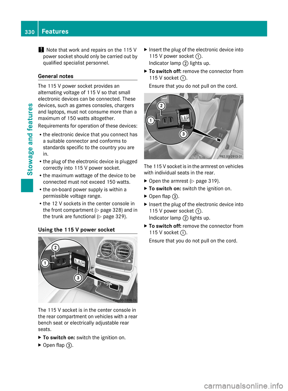
Using the 115 V power socket The 115 V socket is in the center console in
the rear compartment on vehicles with a rear
bench seat or electrically adjustable rear
seats.
X To switch on: switch the ignition on.
X Open flap 0087. X
Insert the plug of the electronic device into
115 V power socket 0043.
Indicator lamp 0044lights up.
X To switch off: remove the connector from
115 V socket 0043.
Ensure that you do not pull on the cord. The 115 V socket is in the armrest on vehicles
with individual seats in the rear.
X Open the armrest (Y page 319).
X To switch on: switch the ignition on.
X Open flap 0087.
X Insert the plug of the electronic device into
115 V power socket 0043.
Indicator lamp 0044lights up.
X To switch off: remove the connector from
115 V socket 0043.
Ensure that you do not pull on the cord. 330
FeaturesStowage and features
Page 333 of 434
Problems with the 115 V power socket
Problem Possible causes/consequences and
0050
0050Solutions The warning lamp on
the 115 V power socket
is not lit. The on-board voltage is too low because the battery is too weak.
X
Start the engine.
or
X Charge the battery (Y page 371).
If the indicator lamp still does not light up:
X Visit a qualified specialist workshop. The temperature of the DC/AC converter is temporarily too high.
X
Remove the electronic device connector from the 115 V socket.
X Let the DC/AC converter cool down.
If the indicator lamp still does not light up after cooling down the
converter:
X Visit a qualified specialist workshop. You have connected an electronic device that has a constant
nominal power of less than 150 watts, but has a very high switch-
on current. This device will not work. If you connect such a device,
the 115 V power socket will not supply it with power.
X Connect a suitable electronic device. Coolbox in the rear compartment
Important safety notes G
WARNING
If you cover the ventilation grille for the
coolbox, it may overheat. There is a risk of fire.
Always make sure that the ventilation grille is
not covered.
The ventilation grille for the coolbox is in the
trunk.
The coolbox can bear a maximum load of
7.7 lb (3.5 kg).
If you want to store a bottle in the upper
compartment of the coolbox, the capacity of
the bottle must not exceed 17 fl. oz. (0.5 l).
Store only plastic bottles in the upper
compartment of the coolbox. Using the coolbox
X
Vehicles with rear seat armrest: fold
down the rear seat armrest.
X Pull handle 0043and fold down cover 0044. Features
331Stowage and features Z
Page 334 of 434
X
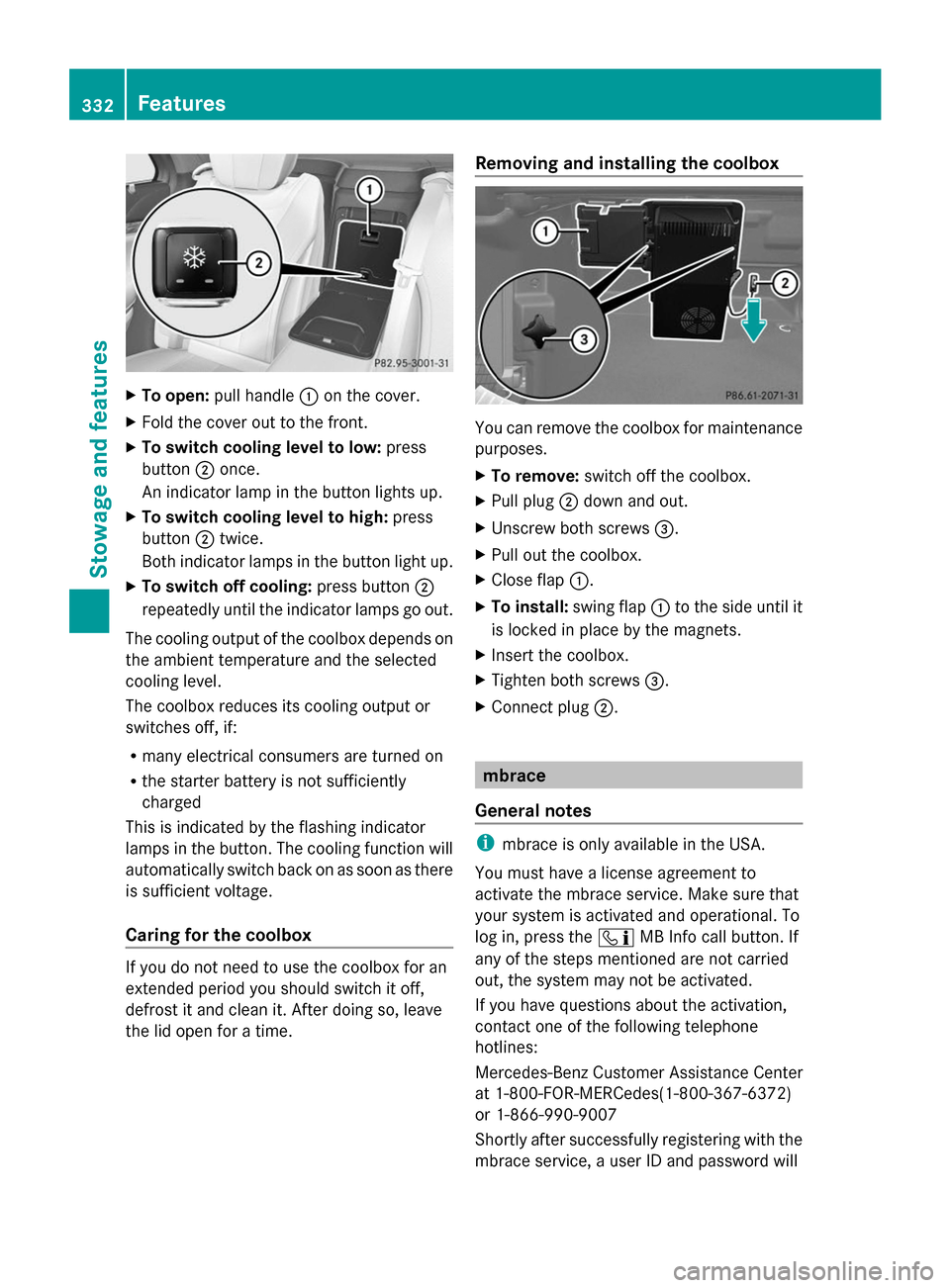
To open: pull handle 0043on the cover.
X Fold the cover out to the front.
X To switch cooling level to low: press
button 0044once.
An indicator lamp in the button lights up.
X To switch cooling level to high: press
button 0044twice.
Both indicator lamps in the button light up.
X To switch off cooling: press button0044
repeatedly until the indicator lamps go out.
The cooling output of the coolbox depends on
the ambient temperature and the selected
cooling level.
The coolbox reduces its cooling output or
switches off, if:
R many electrical consumers are turned on
R the starter battery is not sufficiently
charged
This is indicated by the flashing indicator
lamps in the button. The cooling function will
automatically switch back on as soon as there
is sufficient voltage.
Caring for the coolbox If you do not need to use the coolbox for an
extended period you should switch it off,
defrost it and clean it. After doing so, leave
the lid open for a time. Removing and installing the coolbox
You can remove the coolbox for maintenance
purposes.
X
To remove: switch off the coolbox.
X Pull plug 0044down and out.
X Unscrew both screws 0087.
X Pull out the coolbox.
X Close flap 0043.
X To install: swing flap0043to the side until it
is locked in place by the magnets.
X Insert the coolbox.
X Tighten both screws 0087.
X Connect plug 0044. mbrace
General notes i
mbrace is only available in the USA.
You must have a license agreement to
activate the mbrace service. Make sure that
your system is activated and operational. To
log in, press the 00D9MB Info call button. If
any of the steps mentioned are not carried
out, the system may not be activated.
If you have questions about the activation,
contact one of the following telephone
hotlines:
Mercedes-Benz Customer Assistance Center
at 1-800-FOR-MERCedes(1-800-367-6372)
or 1-866-990-9007
Shortly after successfully registering with the
mbrace service, a user ID and password will 332
FeaturesSto
wage an d features
Page 335 of 434

be sent to you by mail. You can use this
password to log onto the mbrace area under
"Owners Online" at http://
www.mbusa.com .
The system is available if:
R it has been activated and is operational
R the corresponding mobile phone network
is available for transmitting data to the
Customer Center
R a service subscription is available
R the starter battery is sufficiently charged
i Determining the location of the vehicle on
a map is only possible if:
R GPS reception is available.
R the vehicle position can be forwarded to
the Customer Assistance Center.
The mbrace system To adjust the volume during a call, proceed
as follows:
X Press the 0081or0082 button on the
multifunction steering wheel.
or
X Use the volume controller of COMAND.
The system offers various services, e.g:
R Automatic and manual emergency call
R Roadside Assistance call
R MB Info call
You can find information and a description of
all available features under "Owners Online"
at http://www.mbusa.com.
System self-test After you have switched on the ignition, the
system carries out a self-diagnosis. A malfunction in the system has been
detected if one of the following occurs:
R
The indicator lamp in the SOS button does
not come on during the system self-test.
R The indicator lamp in the 0052Roadside
Assistance button does not light up during
self-diagnosis of the system.
R The indicator lamp in the 00D9MB Info call
button does not light up during self-
diagnosis of the system.
R The indicator lamp in one or more of the
following buttons continues to light up red
after the system self-diagnosis:
-SOS button
- 0052 Roadside Assistance call button
- 00D9 MB Info call button
R After the system self-diagnosis, the
Inoperative
Inoperative orService Not Service Not
Activated
Activated message appears in the
multifunction display.
If a malfunction is indicated as outlined
above, the system may not operate as
expected. In the event of an emergency, help
will have to be summoned by other means.
Have the system checked at the nearest
authorized Mercedes-Benz Center or contact
the following service hotlines:
Mercedes-Benz Customer Assistance Center
at 1-800-FOR-MERCedes(1-800-367-6372)
or 1-866-990-9007 Features
333Stowage and features Z
Page 343 of 434
include text message, e-mail or an automated
call.
The area can be determined as either a circle
or a polygon with a maximum of ten corners.
You can specify up to ten areas
simultaneously. Different settings are
possible for each area.
These settings can be called up under
"Owners Online" at http://www.mbusa.com.
Alternatively, you can trigger an MB Info call
and inform the customer service
representative that you wish to activate geo
fencing.
Currently inactive areas can be activated by
text message.
Triggering the vehicle alarm With this function, you can trigger the
vehicle's panic alarm via text message. An
alarm sounds and the exterior lighting
flashes. Depending on the setting, the panic
alarm lasts five or ten seconds. Afterwards,
the alarm switches off. Garage door opener
General notes The HomeLink
®
garage door opener
integrated in the rear-view mirror allows you
to operate up to three different door and gate
systems.
Use the integrated garage door opener only
on garage doors that:
R have safety stop and reverse features and
R meet current U.S. federal safety standards
Once programed, the integrated garage door
opener in the rear-view mirror will assume the
function of the garage door system's remote
control. Please also read the operating
instructions for the garage door system.
When programing a garage door opener, park
the vehicle outside the garage. Do not run the
engine while programing. Certain garage door drives are incompatible
with the integrated garage door opener. If you
have difficulty programing the integrated
garage door opener, contact an authorized
Mercedes-Benz Center.
Alternatively, you can call the following
telephone assistance services:
R
USA: Mercedes-Benz Customer Assistance
Center at 1-800-FOR-MERCedes
R Canada: Customer Service at
1-800-387-0100
R HomeLink ®
hotline 1-800-355-3515 (free
of charge)
More information on HomeLink ®
and/or
compatible products is also available online
at http://www.homelink.com.
Notes on the declaration of conformity
(Y page 26).
USA: FCC ID: CB2HMIHL4
Canada: IC: 279B-HMIHL4
Important safety notes G
WARNING
When you operate or program the garage door
with the integrated garage door opener,
persons in the range of movement of the
garage door can become trapped or struck by
the garage door. There is a risk of injury.
When using the integrated garage door
opener, always make sure that nobody is
within the range of movement of the garage
door. G
WARNING
Combustion engines emit poisonous exhaust
gases such as carbon monoxide. Inhaling
these exhaust gases leads to poisoning. There
is a risk of fatal injury. Therefore never leave
the engine running in enclosed spaces
without sufficient ventilation. Features
341Stowage and features Z
Page 344 of 434
Programing
Programing buttons
Pay attention to the "Important safety notes"
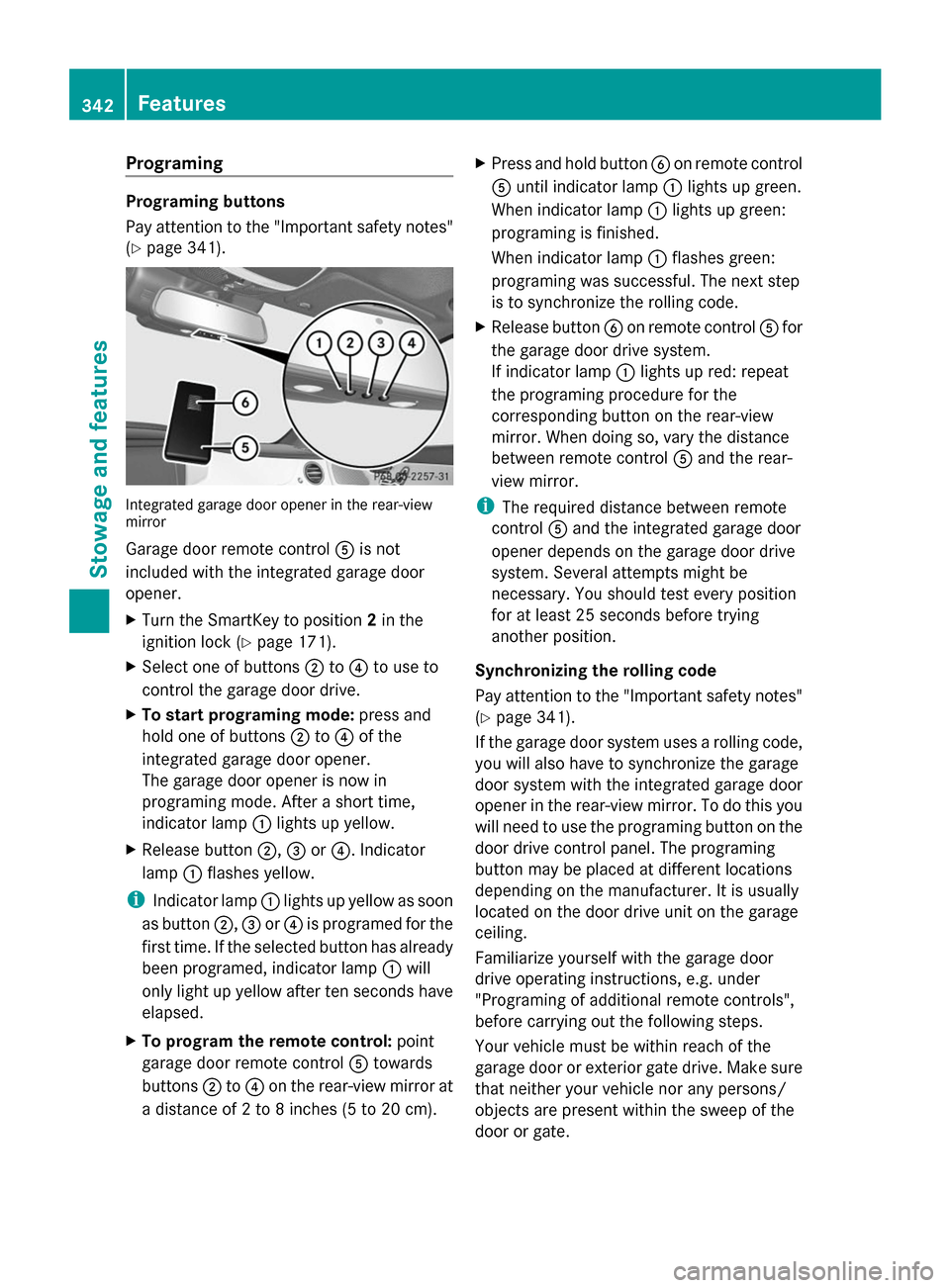
(Y page 341). Integrated garage door opener in the rear-view
mirror
Garage door remote control
0083is not
included with the integrated garage door
opener.
X Turn the SmartKey to position 2in the
ignition lock (Y page 171).
X Select one of buttons 0044to0085 to use to
control the garage door drive.
X To start programing mode: press and
hold one of buttons 0044to0085 of the
integrated garage door opener.
The garage door opener is now in
programing mode. After a short time,
indicator lamp 0043lights up yellow.
X Release button 0044,0087or0085. Indicator
lamp 0043flashes yellow.
i Indicator lamp 0043lights up yellow as soon
as button 0044,0087or0085 is programed for the
first time. If the selected button has already
been programed, indicator lamp 0043will
only light up yellow after ten seconds have
elapsed.
X To program the remote control: point
garage door remote control 0083towards
buttons 0044to0085 on the rear-view mirror at
a distance of 2 to 8 inches (5 to 20 cm). X
Press and hold button 0084on remote control
0083 until indicator lamp 0043lights up green.
When indicator lamp 0043lights up green:
programing is finished.
When indicator lamp 0043flashes green:
programing was successful. The next step
is to synchronize the rolling code.
X Release button 0084on remote control 0083for
the garage door drive system.
If indicator lamp 0043lights up red: repeat
the programing procedure for the
corresponding button on the rear-view
mirror. When doing so, vary the distance
between remote control 0083and the rear-
view mirror.
i The required distance between remote
control 0083and the integrated garage door
opener depends on the garage door drive
system. Several attempts might be
necessary. You should test every position
for at least 25 seconds before trying
another position.
Synchronizing the rolling code
Pay attention to the "Important safety notes"
(Y page 341).
If the garage door system uses a rolling code,
you will also have to synchronize the garage
door system with the integrated garage door
opener in the rear-view mirror. To do this you
will need to use the programing button on the
door drive control panel. The programing
button may be placed at different locations
depending on the manufacturer. It is usually
located on the door drive unit on the garage
ceiling.
Familiarize yourself with the garage door
drive operating instructions, e.g. under
"Programing of additional remote controls",
before carrying out the following steps.
Your vehicle must be within reach of the
garage door or exterior gate drive. Make sure
that neither your vehicle nor any persons/
objects are present within the sweep of the
door or gate. 342
FeaturesStowage and features
Page 345 of 434
X
Turn the SmartKey to position 2in the
ignition lock (Y page 171).
X Get out of the vehicle.
X Press the programing button on the door
drive unit.
i Usually, you now have 30 seconds to
initiate the next step.
X Get into the vehicle.
X Press previously programed button 0044,0087
or 0085 of the integrated garage door opener
until the door closes.
The rolling code synchronization is then
complete.
Notes on programing the remote control
Canadian radio frequency laws require a
"break" (or interruption) of the transmission
signals after broadcasting for a few seconds.
Therefore, these signals may not last long
enough for the integrated garage door
opener. The signal is not recognized during
programing. Comparable with Canadian law,
some U.S. garage door openers also feature
a "break".
Proceed as follows:
R if you live in Canada
R if you have difficulties programing the
garage door opener (regardless of where
you live) when using the programing steps
X Press and hold one of buttons 0044to0085 on
the integrated garage door opener.
After a short time, indicator lamp 0043lights
up yellow.
X Release the button.
Indicator lamp 0043flashes yellow.
X Press button 0084of garage door remote
control 0083for two seconds, then release it
for two seconds.
X Press button 0084again for two seconds.
X Repeat this sequence on button 0084of
remote control 0083until indicator lamp 0043
lights up green.
When indicator lamp 0043lights up green:
programing is finished. When indicator lamp
0043flashes green:
programing was successful. The next step
is to synchronize the rolling code.
X Release button 0084of remote control 0083of
the garage door drive.
If indicator lamp 0043blinks red: repeat the
programing process for the corresponding
button on the rear-view mirror. When doing
so, vary the distance between remote
control 0083and the rear-view mirror.
i The required distance between remote
control 0083and the integrated garage door
opener depends on the garage door drive
system. Several attempts might be
necessary. You should test every position
for at least 25 seconds before trying
another position.
Problems when programing
If you are experiencing problems programing
the integrated garage door opener on the
rear-view mirror, take note of the following
instructions:
R Check the transmitter frequency used by
garage door drive remote control 0083and
whether it is supported. The transmitter
frequency can usually be found on the back
of the garage door drive remote control.
The integrated garage door opener is
compatible with devices that have units
which operate in the frequency range of
280 to 433 MHz.
R Replace the batteries in garage door
remote control 0083. This increases the
likelihood that garage door remote control
0083 will transmit a strong and precise signal
to the integrated garage door opener in the
rear-view mirror.
R When programing, hold remote control 0083
at varying distances and angles from the
button that you are programing. Try various
angles at a distance between 2and
12 inches (5to 30 cm) or at the same angle
but at varying distances. Features
343Stowage and features Z
Page 346 of 434
R
If another remote control for the same
garage door drive is available, repeat the
same programing steps with this remote
control. Before performing these steps,
make sure that new batteries have been
installed in garage door drive remote
control 0083.
R Note that some remote controls only
transmit for a limited amount of time (the
indicator lamp on the remote control goes
out). Press button 0084on remote control
0083 again before transmission ends.
R Align the antenna cable of the garage door
opener unit. This can improve signal
reception/transmission.
Opening/closing the garage door After it has been programed, the integrated
garage door opener performs the function of
the garage door system remote control.
Please also read the operating instructions
for the garage door system.
X Turn the SmartKey to position 2in the
ignition lock (Y page 171).
X Press button 0044,0087or0085 which you have
programed to operate the garage door.
Garage door system with a fixed code:
indicator lamp 0043lights up green.
Garage door system with a rolling code:
indicator lamp 0043flashes green.
i The transmitter will transmit a signal as
long as the button is pressed. The
transmission is halted after a maximum of
ten seconds and indicator lamp 0043lights
up yellow. Press button 0044,0087or0085 again
if necessary.
Clearing the memory Make sure that you clear the memory of the
integrated garage door opener before selling
the vehicle. X
Turn the SmartKey to position 2in the
ignition lock (Y page 171).
X Press and hold buttons 0044and 0085.
The indicator lamp initially lights up yellow
and then green.
X Release buttons 0044and 0085.
The memory of the integrated garage door
opener in the rear-view mirror is cleared. Floormats
G
WARNING
Objects in the driver's footwell can restrict the
pedal travel or obstruct a depressed pedal.
The operating and road safety of the vehicle
is jeopardized. There is a risk of an accident.
Make sure that all objects in the vehicle are
stowed correctly, and that they cannot enter
the driver's footwell. Install the floormats
securely and as specified in order to ensure
sufficient clearance for the pedals. Do not use
loose floormats and do not place floormats on
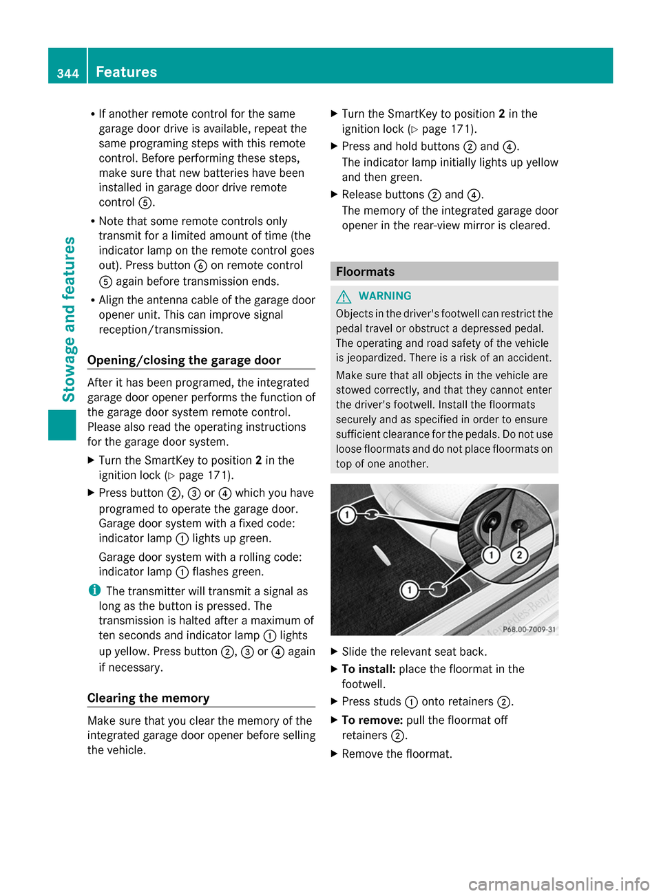
top of one another. X
Slide the relevant seat back.
X To install: place the floormat in the
footwell.
X Press studs 0043onto retainers 0044.
X To remove: pull the floormat off
retainers 0044.
X Remove the floormat. 344
FeaturesStowage and features