2014 MERCEDES-BENZ S-CLASS COUPE door lock
[x] Cancel search: door lockPage 372 of 413

Fitting/removing the towing eye
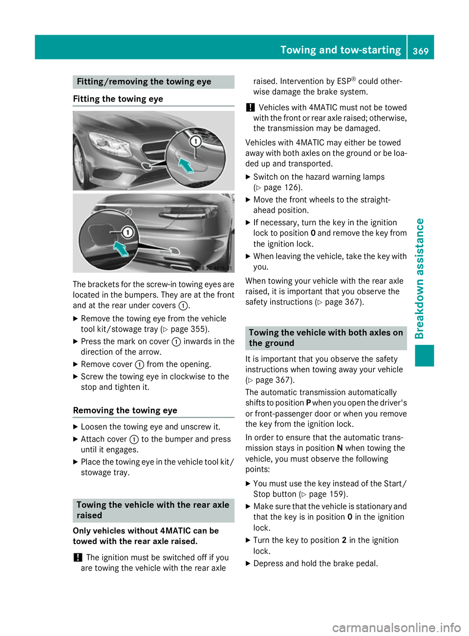
Fitting the towing eye The brackets for the screw-in towing eyes are
located in the bumpers. They are at the front and at the rear under covers :.
X Remove the towing eye from the vehicle
tool kit/stowage tray (Y page 355).
X Press the mark on cover :inwards in the
direction of the arrow.
X Remove cover :from the opening.
X Screw the towing eye in clockwise to the
stop and tighten it.
Removing the towing eye X
Loosen the towing eye and unscrew it.
X Attach cover :to the bumper and press
until it engages.
X Place the towing eye in the vehicle tool kit/
stowage tray. Towing the vehicle with the rear axle
raised
Only vehicles without 4MATIC can be
towed with the rear axle raised.
! The ignition must be switched off if you
are towing the vehicle with the rear axle raised. Intervention by ESP
®
could other-
wise damage the brake system.
! Vehicles with 4MATIC must not be towed
with the front or rear axle raised; otherwise,
the transmission may be damaged.
Vehicles with 4MATIC may either be towed
away with both axles on the ground or be loa- ded up and transported.
X Switch on the hazard warning lamps
(Y page 126).
X Move the front wheels to the straight-
ahead position.
X If necessary, turn the key in the ignition
lock to position 0and remove the key from
the ignition lock.
X When leaving the vehicle, take the key with
you.
When towing your vehicle with the rear axle
raised, it is important that you observe the
safety instructions (Y page 367). Towing the vehicle with both axles on
the ground
It is important that you observe the safety
instructions when towing away your vehicle
(Y page 367).
The automatic transmission automatically
shifts to position Pwhen you open the driver's
or front-passenger door or when you remove the key from the ignition lock.
In order to ensure that the automatic trans-
mission stays in position Nwhen towing the
vehicle, you must observe the following
points:
X You must use the key instead of the Start/
Stop button (Y page 159).
X Make sure that the vehicle is stationary and
that the key is in position 0in the ignition
lock.
X Turn the key to position 2in the ignition
lock.
X Depress and hold the brake pedal. Towing and tow-starting
369Breakdown assistance Z
Page 374 of 413

the colour and fuse rating. The fuse ratings
are listed in the fuse allocation chart.
The fuse allocation chart is on the fuse box in
the boot (Y page 372).
If the newly inserted fuse also blows, have the cause traced and rectified at a qualified spe-
cialist workshop, e.g. a Mercedes-Benz Ser-
vice Centre.
! Only use fuses that have been approved
for Mercedes-Benz vehicles and which
have the correct fuse rating for the system
concerned. Otherwise, components or sys-
tems could be damaged.
The fuses in your vehicle disconnect faulty
circuits. If a fuse blows, all the components on the circuit and their functions will fail. Before replacing a fuse
X Secure the vehicle against rolling away
(Y page 178).
X Switch off all electrical consumers.
X Make sure that the ignition is switched off
(Y page 159).
or
X When using the key, turn the key to position
0 in the ignition lock and remove it
(Y page 159).
All indicator lamps in the instrument cluster
must be off.
The fuses are located in various fuse boxes:
R Fuse box on the driver's side of the dash-
board
R Fuse box in the front-passenger footwell
R Fuse box in the engine compartment on the
left-hand side of the vehicle, when viewed
in the direction of travel
R Fuse box in the boot on the right-hand side
of the vehicle, when viewed in the direction
of travel Dashboard fuse box
! Do not use a pointed object such as a
screwdriver to open the cover in the dash-
board. You could damage the dashboard or
the cover.
! Make sure that no moisture can enter the
fuse box when the cover is open.
! When closing the cover, make sure that it
is lying correctly on the fuse box. Moisture seeping in or dirt could otherwise impair
the operation of the fuses. X
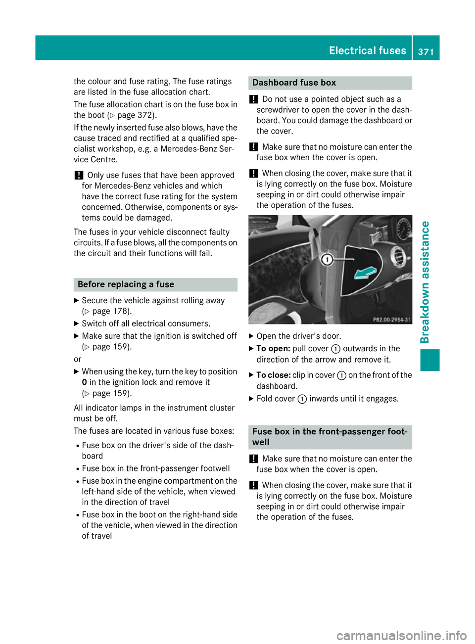
Open the driver's door.
X To open: pull cover :outwards in the
direction of the arrow and remove it.
X To close: clip in cover :on the front of the
dashboard.
X Fold cover :inwards until it engages. Fuse box in the front-passenger foot-
well
! Make sure that no moisture can enter the
fuse box when the cover is open.
! When closing the cover, make sure that it
is lying correctly on the fuse box. Moisture seeping in or dirt could otherwise impair
the operation of the fuses. Electrical fuses
371Breakdown assistance Z
Page 390 of 413

X
Open the driver's door.
The on-board electronics now have status
0. This is the same as the key having been
removed.
X Remove the Start/Stop button from the
ignition lock (Y page 159).
or, if the key is inserted in the ignition lock: X Remove the key from the ignition lock.
X If included in the vehicle equipment,
remove the tyre-change tool kit from the
vehicle.
X Secure the vehicle to prevent it from rolling
away.
i Apart from some country-specific var-
iants, vehicles are not equipped with tyre-
changing tools. Some tools for changing a
wheel are specific to the vehicle. For more information on which tools are required to
perform a wheel change on your vehicle,
consult a qualified specialist workshop.
Necessary wheel-changing tools may
include, for example:
R Jack
R Wheel chock
R Wheel wrench
R Centring pin
Securing the vehicle against rolling
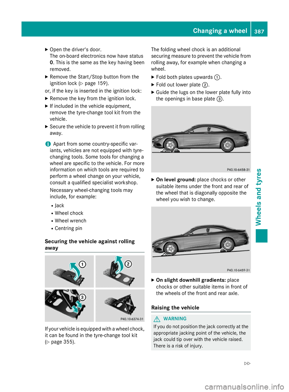
away If your vehicle is equipped with a wheel chock,
it can be found in the tyre-change tool kit
(Y page 355). The folding wheel chock is an additional
securing measure to prevent the vehicle from
rolling away, for example when changing a
wheel.
X Fold both plates upwards :.
X Fold out lower plate ;.
X Guide the lugs on the lower plate fully into
the openings in base plate =. X
On level ground: place chocks or other
suitable items under the front and rear of
the wheel that is diagonally opposite the
wheel you wish to change. X
On slight downhill gradients: place
chocks or other suitable items in front of
the wheels of the front and rear axle.
Raising the vehicle G
WARNING
If you do not position the jack correctly at the appropriate jacking point of the vehicle, the
jack could tip over with the vehicle raised.
There is a risk of injury. Changing a wheel
387Wheels and tyres
Z
Page 391 of 413

Only position the jack at the appropriate jack-
ing point of the vehicle. The base of the jack
must be positioned vertically, directly under
the jacking point of the vehicle.
Observe the following when raising the
vehicle:
R to raise the vehicle, only use the vehicle-
specific jack that has been tested and
approved by Mercedes-Benz. If the jack is
used incorrectly, it could tip over while the vehicle is raised.
R the jack is designed only to raise and hold
the vehicle for a short time while a wheel
is being changed. It is not suitable for per-
forming maintenance work under the vehi- cle.
R avoid changing the wheel on uphill and
downhill slopes.
R before raising the vehicle, secure it from
rolling away by applying the parking brake
and positioning wheel chocks. Do not
release the parking brake while the vehicle
is raised.
R the jack must be placed on a firm, flat and
non-slip surface. On a loose surface, a
large, flat load-bearing underlay must be
used. On a slippery surface, a non-slip
underlay must be used, e.g. rubber mats.
R do not use wooden blocks or similar
objects as a jack underlay. Otherwise, the
jack will not be able to achieve its load-
bearing capacity due to the restricted
height.
R make sure that the distance between the
underside of the tyres and the ground does
not exceed 3 cm.
R never place your hands or feet under the
raised vehicle.
R do not lie under the vehicle.
R do not start the engine when the vehicle is
raised. R
do not open or close a door or the boot lid
when the vehicle is raised.
R make sure that no persons are present in
the vehicle when the vehicle is raised.
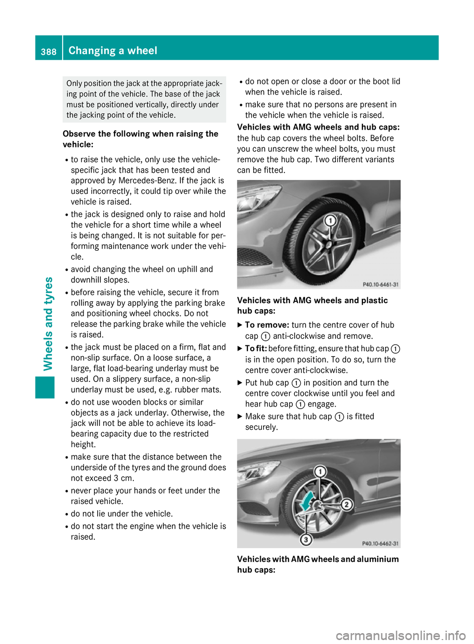
Vehicles with AMG wheels and hub caps:
the hub cap covers the wheel bolts. Before
you can unscrew the wheel bolts, you must
remove the hub cap. Two different variants
can be fitted. Vehicles with AMG wheels and plastic
hub caps:
X To remove: turn the centre cover of hub
cap :anti-clockwise and remove.
X To fit: before fitting, ensure that hub cap :
is in the open position. To do so, turn the
centre cover anti-clockwise.
X Put hub cap :in position and turn the
centre cover clockwise until you feel and
hear hub cap :engage.
X Make sure that hub cap :is fitted
securely. Vehicles with AMG wheels and aluminium
hub caps: 388
Changing a wheelWheels and tyres