2014 MERCEDES-BENZ GLK-CLASS SUV mirror
[x] Cancel search: mirrorPage 196 of 384

; Yellow guide line at a distance of
approximately 13 ft (4.0 m) from the rear
of the vehic")
:
White guide line without turning the
steering wheel, vehicle width including
the exterior mirrors (static)
; Yellow guide line at a distance of
approximately 13 ft (4.0 m) from the rear
of the vehicle
= Red guide line for the vehicle width
including the exterior mirrors, for current
steering wheel angle (dynamic)
? Yellow lane marking tires at current
steering wheel angle (dynamic) A
Yellow guide line at a distance of
approximately 3 ft (1.0 m) from the rear
of the vehicle
B Vehicle center axle (marker assistance)
C Bumper
D Red guide line at a distance of
approximately 12 in (0.30 m) from the
rear of the vehicle
The guide lines are shown when the
transmission is in position R.
The distance specifications only apply to
objects that are at ground level. Additional messages for vehicles with
PARKTRONIC
:
Front warning display
; Additional PARKTRONIC measurement
operational readiness indicator
= Rear warning display
Vehicles with PARKTRONIC: if
PARKTRONIC is operational (Y page 186), an
additional operational readiness indicator will
appear in COMAND display ;. If the
PARKTRONIC warning displays are active or
light up, warning displays :and =are also
active or light up correspondingly in the
COMAND display.
"Reverse parking" function X
Make sure that the rear view camera is
activated and the "Reverse parking"
function is selected; see the separate
operating instructions for the audio
system/COMAND.
The lane and the guide lines are shown. 194
Driving systemsDriving and parking
Page 197 of 384

; Red guide lin")
Backing up straight into a parking space
without turning the steering wheel :
White guide line without turning the
steering wheel, vehicle width including
the exterior mirrors (static)
; Red guide line for the vehicle width
including the exterior mirrors, for current
steering wheel angle (dynamic)
= Yellow guide line at a distance of
approximately 3 ft (1.0 m) fromthe rear
of the vehicle
? Red guide line at a distance of
approximately 12 in (0.30 m) fromthe
rear of the vehicle
X Make sure that the rear view camera is
switched on (Y page 193).
The lane and the guide lines are shown.
X With the help of white guide line :, check
whether the vehicle will fit into the parking
space.
X Using white guide line :as a guide,
carefully back up until you reach the end
position.
Red guide line ?is then at the end of the
parking space. The vehicle is almost
parallel in the parking space. Reverse perpendicular parking with the
steering wheel at an angle Turning the steering wheel
:
Red guide line for the vehicle width
including the exterior mirrors, for current
steering wheel angle (dynamic)
; Parking space marking
X Make sure that the rear view camera is
switched on (Y page 193).
The lane and the guide lines are shown.
X Drive past the parking space and bring the
vehicle to a standstill.
X While the vehicle is at a standstill, turn the
steering wheel in the direction of the
parking space until yellow guide line :
reaches parking space marking ;.
X Keep the steering wheel in that position
and back up carefully. Backing up with the steering wheel turned
:
Red guide line for the vehicle width
including the exterior mirrors, for current
steering wheel angle (dynamic) Driving systems
195Driving and parking Z
Page 199 of 384
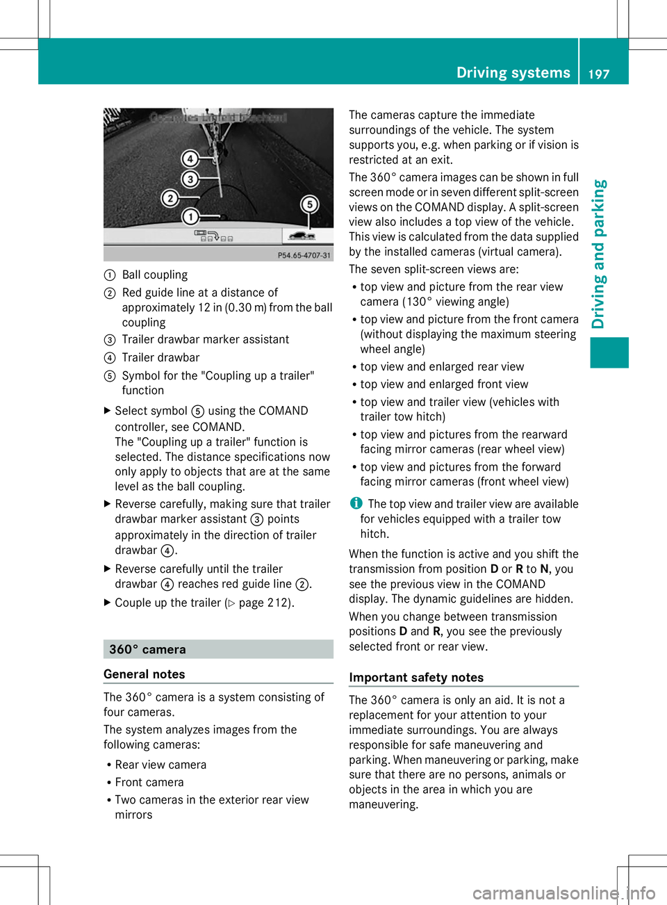
:
Ball coupling
; Red guide line at a distance of
approximately 12 in (0.30 m)from the ball
coupling
= Trailer drawbar marker assistant
? Trailer drawbar
A Symbol for the "Coupling up a trailer"
function
X Select symbol Ausing the COMAND
controller, see COMAND.
The "Coupling up a trailer" function is
selected. The distance specifications now
only apply to objects that are at the same
level as the ball coupling.
X Reverse carefully, making sure that trailer
drawbar marker assistant =points
approximately in the direction of trailer
drawbar ?.
X Reverse carefully until the trailer
drawbar ?reaches red guide line ;.
X Couple up the trailer (Y page 212).360° camera
General notes The 360° camera is a system consisting of
four cameras.
The system analyzes images from the
following cameras:
R Rear view camera
R Front camera
R Two cameras in the exterior rear view
mirrors The cameras capture the immediate
surroundings of the vehicle. The system
supports you, e.g. when parking or if vision is
restricted at an exit.
The 360° camera images can be shown in full
screen mode or in seven different split-screen
views on the COMAND display. A split-screen
view also includes a top view of the vehicle.
This view is calculated from the data supplied
by the installed cameras (virtual camera).
The seven split-screen views are:
R
top view and picture from the rear view
camera (130° viewing angle)
R top view and picture from the front camera
(without displaying the maximum steering
wheel angle)
R top view and enlarged rear view
R top view and enlarged front view
R top view and trailer view (vehicles with
trailer tow hitch)
R top view and pictures from the rearward
facing mirror cameras (rear wheel view)
R top view and pictures from the forward
facing mirror cameras (front wheel view)
i The top view and trailer view are available
for vehicles equipped with a trailer tow
hitch.
When the function is active and you shift the
transmission from position Dor Rto N, you
see the previous view in the COMAND
display. The dynamic guidelines are hidden.
When you change between transmission
positions Dand R, you see the previously
selected front or rear view.
Important safety notes The 360° camera is only an aid. It is not a
replacement for your attention to your
immediate surroundings. You are always
responsible for safe maneuvering and
parking. When maneuvering or parking, make
sure that there are no persons, animals or
objects in the area in which you are
maneuvering. Driving systems
197Driving and parking Z
Page 200 of 384

The 360° camera may show a distorted view
of obstacles, show them incorrectly or not at
all. It cannot show objects in the following
areas:
R under the front bumper
R very close to the front bumper
R very close to the rear bumper
R under the rear bumper
R in close range above the handle on the
trunk lid
R very close to the exterior mirrors
You are always responsible for safety, and
must always pay attention to your
surroundings when parking and
maneuvering. This applies to the areas
behind, in front of and beside the vehicle. You
could otherwise endanger yourself and
others.
The 360° camera will not function or will
function in a limited manner:
R if the doors are open
R if the exterior mirrors are folded in
R the tailgate is open
R in heavy rain, snow or fog
R at night or in very dark places
R if the cameras are exposed to very bright
light
R if the area is lit by fluorescent light or LED
lighting (the display may flicker)
R if you exit a heated garage in winter,
resulting in a rapid change in temperature
R if the camera lenses are dirty or covered
R if the vehicle components in which the
cameras are installed are damaged. In this
event, have the camera position and setting
checked at a qualified specialist workshop.
Do not use the 360° camera in this case. You
can otherwise injure others or cause damage
to objects or the vehicle. Activation conditions The 360° camera image can be displayed if:
R
your vehicle is equipped with a 360°
camera
R COMAND is switched on, see the separate
COMAND operating instructions
R the 360° Camera 360° Camera function is activated
Activating the 360° camera using the
SYS button X
Press and hold the Wbutton for longer
than 2 seconds, see the separate COMAND
operating instructions.
Depending on whether position Dor Ris
engaged, the following is shown:
R full screen display with the image from
the front camera
R full screen display with the image from
the rear camera
Activating the 360° camera with
COMAND X
Press the Wbutton, see the separate
COMAND operating instructions.
X Select System
System by turning cVdthe
COMAND controller and press Wto
confirm.
X Select 360° Camera
360° Camera and pressWto
confirm.
Depending on whether position Dor Ris
engaged, the following is shown:
R a split screen with top view and the
image from the front camera or
R a split screen with top view and the
image from the rear view camera
For further information about the COMAND
controller, see the separate COMAND
operating instructions. 198
Driving systemsDriving and parking
Page 201 of 384

Activating the 360° camera using
reverse gear The 360° camera images can be
automatically displayed by engaging reverse
gear.
X Make sure that the SmartKey is in position
2in the ignition lock.
X Make sure that the Activation by R Activation by R
gear
gear setting is active in COMAND, see the
separate COMAND operating instructions.
X To show the 360° camera image: engage
reverse gear.
The COMAND display shows the area
behind the vehicle in split screen:
R vehicle with guide lines
R top view of the vehicle
Selecting the split-screen and full
screen displays X
To switch between split screen views:
switch to the line with the vehicle icons by
sliding ZVthe COMAND controller.
X Turn cVd the COMAND controller and
select one of the vehicle symbols.
X To switch to full screen mode: select
Full Screen
Full Screen by turningcVdthe
COMAND controller and press Wto
confirm.
Displays in the COMAND display Important safety notes
!
Objects not at ground level may appear to
be further away than they actually are, e.g.:
R the bumper of a parked vehicle
R the drawbar of a trailer
R the ball coupling of a trailer tow hitch
R the rear section of an HGV
R a slanted post
Use the guidelines only for orientation.
Approach objects no further than the
bottom-most guideline. Top view with picture from the rear view
camera
:
Symbol for the split screen setting with
top view and rear view camera image
; Yellow guide line at a distance of
approximately 13 ft (4.0 m) from the rear
of the vehicle
= Yellow guide line for the vehicle width
including the exterior mirrors, for current
steering wheel angle (dynamic)
? Yellow lane marking tires at current
steering wheel angle (dynamic) A
Yellow guide line at a distance of
approximately 3 ft (1.0 m) from the rear
of the vehicle
B Vehicle center axle (marker assistance)
C Red guide line at a distance of
approximately 12 in (0.30 m) from the
rear of the vehicle
D Bumper
The guide lines are shown when the
transmission is in position R.
The distance specifications only apply to
objects that are at ground level. Driving systems
199Driving and parking Z
Page 202 of 384
 from the front
o")
Top view with picture from the front
camera :
Symbol for the split screen setting with
top view and front camera image
; Yellow guide line at a distance of
approximately 13 ft (4.0 m) from the front
of the vehicle
= Yellow guide line for the vehicle width
including the exterior mirrors, for current
steering wheel angle (dynamic)
? Yellow lane marking tires at current
steering wheel angle (dynamic)
A Yellow guide line at a distance of
approximately 3 ft (1.0 m) fromthe front
of the vehicle
B Red guide line at a distance of
approximately 12 in (0.30 m) fromthe
front of the vehicle Top view and enlarged rear view :
Symbol for the split screen setting with
top view and rear view camera image
enlarged
; Red guide line at a distance of
approximately 12 in (0.30 m) fromthe
rear of the vehicle
This view assists you in estimating the
distance to the vehicle behind you.
i This setting can also be selected as an
enlarged front view.
Top view with picture from the mirror
camera :
Symbol for the top view and forward-
facing mirror camera setting
; Yellow guide line for the vehicle width
including the exterior mirrors (right side
of vehicle)
= Yellow guide line for the vehicle width
including the exterior mirrors (left side of
vehicle) 200
Driving systemsDriving an
d parking
Page 204 of 384
 or faster than
112 mph (180 km/h)")
R
if you have adopted a sporty driving style
with high cornering speeds or high rates of
acceleration
R if you are predominantly driving slower
than 50 mph (80 km/h) or faster than
112 mph (180 km/h)
R if you are currently using COMAND or
making a telephone call with it
R if the time has been set incorrectly
R in active driving situations, such as when
you change lanes or change your speed
Warning and display messages in the
multifunction display X
Activate ATTENTION ASSIST using the on-
board computer (Y page 229).
If ATTENTION ASSIST is active, you will be
warned no sooner than 20 minutes after your
journey has begun. You then hear an
intermittent warning tone twice and the
Attention Assist: Drowsiness
Attention Assist: Drowsiness
detected detected message appears in the
multifunction display.
X If necessary, take a break.
X Press the abutton to confirm the
message.
On long journeys, take regular breaks in good
time to allow yourself to rest properly. If you
do not take a break, you will be warned again
after 15 minutes at the earliest. The
precondition for this is that
ATTENTION ASSIST still detects typical
indicators of fatigue or increasing lapses in
concentration.
ATTENTION ASSIST is reset when you
continue your journey and starts assessing
your tiredness again if:
R you switch off the engine.
R you take off your seat belt and open the
driver's door, e.g. for a change of drivers or
to take a break.
The assistance graphic shows the é
symbol when ATTENTION ASSIST is
deactivated (Y page 228). Lane Tracking package
General notes The Lane Tracking package consists of Blind
Spot Assist (Y
page 202) and Lane Keeping
Assist (Y page 204).
Blind Spot Assist General notes
Blind Spot Assist uses a radar sensor system
to monitor the areas on both sides of your
vehicle. It supports you from a speed of
approximately 20 mph
(30 km/h). A warning
display in the exterior mirrors draws your
attention to vehicles detected in the
monitored area. If you then switch on the
corresponding turn signal to change lanes,
you will also receive a visual and audible
collision warning. Blind Spot Assist uses
sensors in the rear bumper for monitoring
purposes.
For Blind Spot Assist to assist you, the radar
sensor system must be operational.
Important safety notes
Blind Spot Assist is only an aid. It may fail to
detect some vehicles and is no substitute for
attentive driving. Always ensure that there is
sufficient distance to the side for other road
users and obstacles. G
WARNING
Blind Spot Assist does not react to:
R vehicles overtaken too closely on the side,
placing them in the blind spot area
R vehicles which approach with a large speed
differential and overtake your vehicle
As a result, Blind Spot Assist may not give
warnings in such situations. There is a risk of
an accident.
Always observe the traffic conditions
carefully, and maintain a safe lateral distance.
i USA only:
This device has been approved by the FCC
as a "Vehicular Radar System". The radar 202
Driving systemsDriving and parking
Page 205 of 384

sensor is intended for use in an automotive
radar system only. Removing, tampering
with, or altering the device will void any
warranties, and is not permitted by the
FCC. Do not tamper with, alter, or use in
any non-approved way.
Any unauthorized modification to this
device could void the user’s authority to
operate the equipment.
Monitoring range of the sensors
In particular, the detection of obstacles can
be impaired if:
R dirt on the sensors or anything else
covering the sensors
R poor visibility, e.g. due to fog, heavy rain,
snow or spray
R narrow vehicles, e.g. motorcycles or
bicycles
R the road has very wide lanes
R the road has narrow lanes
R you are not driving in the middle of the lane
R there are barriers or similar lane borders
Vehicles in the monitoring range are then not
indicated. Blind Spot Assist monitors the area up to
10 ft (3 m) behind your vehicle and directly
next to your vehicle, as shown in the diagram. If the lanes are narrow, vehicles driving in the
lane beyond the lane next to your vehicle may
be indicated, especially if the vehicles are not
driving in the middle of their lane. This may
be the case if there are vehicles driving at the
inner edge of their lanes.
Due to the nature of the system:
R
warnings may be issued in error when
driving close to crash barriers or similar
solid lane borders.
R the warning is canceled when driving for an
extended period next to long vehicles, such
as trucks.
The two radar sensors for Blind Spot Assist
are integrated into the sides of the rear
bumper. Make sure that the bumper is free of
dirt, ice or slush in the vicinity of the sensors.
The sensors must not be covered, for
example by cycle racks or overhanging loads.
Following a severe impact or in the event of
damage to the bumpers, have the function of
the sensors checked at a qualified specialist
workshop. Blind Spot Assist may otherwise
not work properly.
Indicator and warning display
Blind Spot Assist is not active at speeds below
approximately 20 mph (30 km/h). Vehicles in
the monitoring range are then not indicated. :
Yellow indicator lamp/red warning lamp
When Blind Spot Assist is activated, indicator
lamp :in the exterior mirrors lights up
yellow at speeds of up to 20 mph (30 km/h).
At speeds above 20 mph (30 km/h), the Driving systems
203Driving and parking Z