2014 MERCEDES-BENZ G-CLASS SUV clock
[x] Cancel search: clockPage 74 of 272

!
The weather can change abruptly. It could
start to rain or snow. Make sure that the
sliding sunroof is closed when you leave the
vehicle. The vehicle electronics can be
damaged if water enters the vehicle
interior.
i Resonance noises can occur in addition
to the usual airflow noises when the sliding
sunroof is open. They are caused by minor
pressure fluctuations in the vehicle interior.
Change the position of the sliding sunroof
or open a side window slightly to reduce or
eliminate these noises. Opening and closing the sliding
sunroof
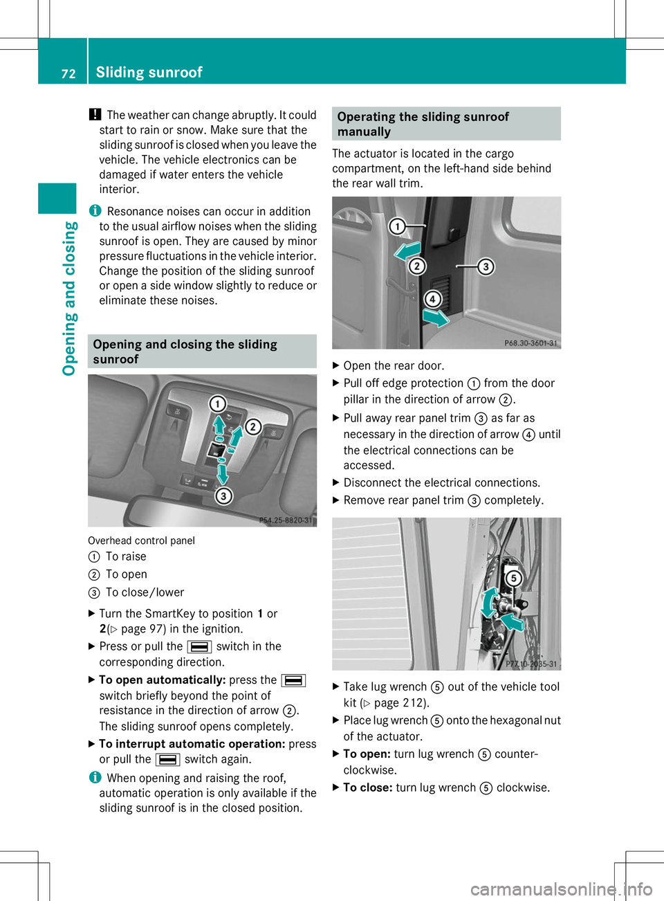
Overhead control panel
:
To raise
; To open
= To close/lower
X Turn the SmartKey to position 1or
2(Y page 97) in the ignition.
X Press or pull the ¡switch in the
corresponding direction.
X To open automatically: press the¡
switch briefly beyond the point of
resistance in the direction of arrow ;.
The sliding sunroof opens completely.
X To interrupt automatic operation: press
or pull the ¡switch again.
i When opening and raising the roof,
automatic operation is only available if the
sliding sunroof is in the closed position. Operating the sliding sunroof
manually
The actuator is located in the cargo
compartment, on the left-hand side behind
the rear wall trim. X
Open the rear door.
X Pull off edge protection :from the door
pillar in the direction of arrow ;.
X Pull away rear panel trim =as far as
necessary in the direction of arrow ?until
the electrical connections can be
accessed.
X Disconnect the electrical connections.
X Remove rear panel trim =completely. X
Take lug wrench Aout of the vehicle tool
kit (Y page 212).
X Place lug wrench Aonto the hexagonal nut
of the actuator.
X To open: turn lug wrench Acounter-
clockwise.
X To close: turn lug wrench Aclockwise. 72
Sliding sunroofOpening and closing
Page 89 of 272

X
Remove dust cover =.
X Push the catch to the side and pull the bulb
holder with the bulb out of housing ;.X
Lightly press bulb ?, turn it counter-
clockwise and pull it out.
X Insert the new bulb and, applying slight
pressure, turn it clockwise until it engages.
X Insert the bulb holder into housing ;.
X Attach dust cover =.
X Insert housing ;.
X Replace and tighten screws :.Windshield wipers
Switching the windshield wipers on/
off G
WARNING
The windshield will no longer be wiped
properly if the wiper blades are worn. This
could prevent you from observing the traffic
conditions, thereby causing an accident. Replace the wiper blades twice a year, ideally
in spring and fall.
Combination switch
1
$ Windshield wipers off
2 Ä Intermittent wipe, low (rain sensor
set to low sensitivity)
3 Å Intermittent wipe, high (rain sensor
set to high sensitivity)
4 ° Continuous wipe, slow
5 ¯ Continuous wipe, fast
B í Single wipe
C î To wipe with washer fluid
X Switch on the ignition.
X Turn the combination switch to the
corresponding position.
In the ÄorÅ position, the appropriate
wiping frequency is set automatically
according to the intensity of the rain. In
the Å position, the rain sensor is more
sensitive than in the Äposition, causing
the windshield wipers to wipe more
frequently. Windshield wipers
87Lights and windshield wipers Z
Page 105 of 272

X
Remove the SmartKey from the ignition
lock.
X Turn the fuel filler cap counterclockwise
and remove it.
X Insert the fuel filler cap into the holder
bracket on the inside of filler flap ?.
Refueling X
Completely insert the filler neck of the fuel
pump nozzle into the tank and refuel.
i Do not add any more fuel after the pump
stops filling for the first time. Otherwise,
fuel may leak out.
Closing X
Replace the fuel filler cap and turn it
clockwise. The fuel filler cap audibly
engages.
X Close the fuel filler flap.
i Close the fuel filler flap before locking the
vehicle. A locking pin otherwise prevents
the fuel filler flap from closing after the
vehicle has been locked. Fuel filler flap emergency release
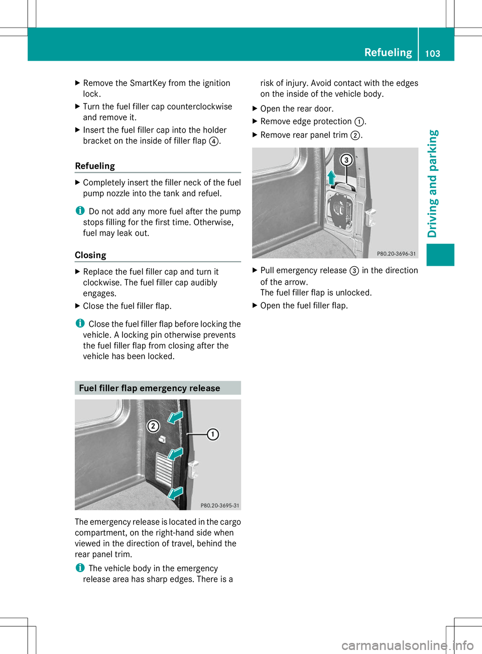
The emergency release is located in the cargo
compartment, on the right-hand side when
viewed in the direction of travel, behind the
rear panel trim.
i The vehicle body in the emergency
release area has sharp edges. There is a risk of injury. Avoid contact with the edges
on the inside of the vehicle body.
X Open the rear door.
X Remove edge protection :.
X Remove rear panel trim ;. X
Pull emergency release =in the direction
of the arrow.
The fuel filler flap is unlocked.
X Open the fuel filler flap. Refueling
103Driving and pa rking Z
Page 180 of 272

The COMAND controller can be:
R
pressed briefly or pressed and held W
R turned clockwise or counter-clockwise
cVd
R slid left or right XVY
R slid forwards or backwards ZVÆ
R slid diagonally aVb
Example of operation In the instructions, operating sequences are
described as follows:
X Press the $button.
Radio mode is activated.
X Select Radio
Radio by sliding VÆand turning
cVd the COMAND controller and press
W to confirm.
X Confirm Station List Station List by pressingW.
The station list appears. Buttons on the COMAND controller
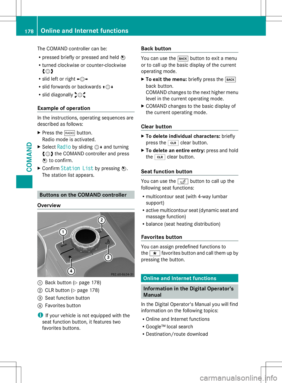
Overview :
Back button (Y page 178)
; CLR button (Y page 178)
= Seat function button
? Favorites button
i If your vehicle is not equipped with the
seat function button, it features two
favorites buttons. Back button You can use the
kbutton to exit a menu
or to call up the basic display of the current
operating mode.
X To exit the menu: briefly press thek
back button.
COMAND changes to the next higher menu
level in the current operating mode.
X COMAND changes to the basic display of
the current operating mode.
Clear button X
To delete individual characters: briefly
press the 2clear button.
X To delete an entire entry: press and hold
the 2 clear button.
Seat function button You can use the
Tbutton to call up the
following seat functions:
R multicontour seat (with 4-way lumbar
support)
R active multicontour seat (dynamic seat and
massage function)
R balance (seat heating distribution)
Favorites button You can assign predefined functions to
the
; favorites button and call them up by
pressing the button. Online and Internet functions
Information in the Digital Operator's
Manual
In the Digital Operator's Manual you will find
information on the following topics:
R Online and Internet functions
R Google™ local search
R Destination/route download 178
Online and Internet functionsCOMAND
Page 205 of 272

engine oils and oil filters tested and
approved in accordance with the
Mercedes-Benz Specifications for Service
Products at any Mercedes-Benz Service
center.
Damage to the engine or exhaust system is
caused by the following:
R using engine oils and oil filters that have
not been specifically approved for the
service system
R replacing engine oil and oil filters after
the interval for replacement specified by
the service system has been exceeded
R using engine oil additives.
! Do not add too much oil. If the oil level is
above the "max" mark on the dipstick, too
much oil has been added. This can lead to
damage to the engine or the catalytic
converter. Have excess oil siphoned off. Example: engine oil cap
X
Turn cap :counter-clockwise and remove
it.
X Add the amount of oil required.
Observe the specifications in the on-board
computer when doing so or fill carefully to the
maximum mark on the oil dipstick.
Further information on engine oil
(Y page 261).
i The difference between the minimum
mark and the maximum mark on the oil
dipstick is approximately 2.1 US qt (2 l).X
Replac e cap:on the filler neck and
tighten clockwise.
Ensure that the cap locks into place
securely. Additional service products
Checking coolant level G
WARNING
The engine cooling system is pressurized,
particularly when the engine is warm. When
opening the cap, you could be scalded by hot
coolant spraying out. There is a risk of injury.
Let the engine cool down before opening the
cap. Wear eye and hand protection when
opening the cap. Open the cap slowly half a
turn to allow pressure to escape. X
Park the vehicle on a level surface.
Only check the coolant level when the
vehicle is on a level surface and the engine
has cooled down.
X Turn the SmartKey to position 2in the
ignition lock (Y page 97).
X Check the coolant temperature display in
the instrument cluster.
The coolant temperature must be below
158 ‡ (70 †).
X Slowly turn cap :half a turn counter-
clockwise to allow excess pressure to
escape. Engine compartment
203Maintenance and care Z
Page 206 of 272

X
Turn cap :further counter-clockwise and
remove it.
If the coolant is at the level of marker bar
= in the filler neck when cold, there is
enough coolant in coolant expansion
tank ;.
If the coolant level is approximately 0.6 in
(1.5 cm) above marker bar =in the filler
neck when warm, there is enough coolant
in expansion tank ;.
X If necessary, add coolant that has been
tested and approved by Mercedes-Benz.
X Replace cap :and turn it clockwise as far
as it will go.
For further information on coolant, see
(Y page 262).
Adding washer fluid to the windshield
washer system/headlamp cleaning
system G
WARNING
Windshield washer concentrate is highly
flammable. If it comes into contact with hot
engine components or the exhaust system it
could ignite. There is a risk of fire and injury.
Make sure that no windshield washer
concentrate is spilled next to the filler neck. Example: washer fluid reservoir
X
To open: pull cap:upwards by the tab.
X Add the premixed washer fluid.
X To close: press cap :onto the filler neck
until it engages. Further information on windshield washer
fluid/antifreeze (Y
page 263).
Brake fluid level !
If you notice that the brake fluid level in
the brake fluid reservoir has fallen to the
MIN mark or less, check the brake system
immediately for leaks. Also check the
thickness of the brake linings. Visit a
qualified specialist workshop immediately.
Do not add brake fluid. This does not
correct the error. Only check the brake fluid level when the
vehicle is on a level surface.
If the brake fluid level is between MIN
mark
:and MAX mark ;on the brake fluid
reservoir, it is correct. Maintenance
Service interval display
Service messages Information on the type of service and service
intervals (see the separate Maintenance
Booklet).
You can obtain further information from an
authorized Mercedes-Benz Center or at
http://www.mbusa.com (USA only).
The ASSYST service interval display informs
you of the next service due date.
If a service due date has been exceeded, you
also hear a warning tone.204
MaintenanceMaintenance and care
Page 219 of 272

disconnected at a qualified specialist
workshop. You can also charge the battery
with a charger recommended by Mercedes-
Benz. Contact a qualified specialist workshop
for further information.
Explosive gases are created during charging
and jump-starting.
For safety reasons, Mercedes-Benz
recommends that you only use batteries
which have been tested and approved for
your vehicle by Mercedes-Benz. These
batteries provide increased impact
protection to prevent vehicle occupants from
suffering acid burns should the battery be
damaged in the event of an accident.
Have the battery condition of charge checked
more frequently if you use the vehicle mainly
for short trips or if you leave it standing idle
for a lengthy period. Consult a qualified
specialist workshop if you wish to leave your
vehicle parked for a long period of time.
i Remove the SmartKey if you park the
vehicle and do not require any electrical
consumers. The vehicle will then use very
little energy, thus conserving battery
power.
i If the power supply has been interrupted,
e.g. due to a discharged battery, you will
have to:
R set the clock. Information on setting the
clock can be found in the Digital
Operator's Manual.
On vehicles with COMAND and a
navigation system, the clock is set
automatically.
R reset the head restraints on the front
seats. Information on adjusting the head
restraints can be found in the Digital
Operator's Manual.
R reset the function for folding the exterior
mirrors in/out automatically, by folding
the mirrors out once (Y page 79). Charging the battery
G
WARNING
During charging and jump-starting, explosive
gases can escape from the battery. There is a
risk of an explosion.
Particularly avoid fire, open flames, creating
sparks and smoking. Ensure there is sufficient
ventilation while charging and jump-starting.
Do not lean over a battery. G
WARNING
Battery acid is caustic. There is a risk of injury.
Avoid contact with the skin, eyes or clothing.
Do not inhale any battery gases. Do not lean
over the battery. Keep children away from
batteries. Wash battery acid immediately with
water and seek medical attention. G
WARNING
A discharged battery can freeze at
temperatures below freezing point. When
jump-starting the vehicle or charging the
battery, gases can escape from the battery.
There is a risk of an explosion.
Allow the frozen battery to thaw out before
charging it or jump-starting.
! Only charge the battery using the jump-
starting connection point.
! Only use battery chargers with a
maximum charging voltage of 14.8 V.
! Only charge the installed battery with a
battery charger which has been tested and
approved by Mercedes-Benz. These battery
chargers allow the battery to be charged
while still installed in the vehicle.
A battery charger unit specially adapted for
Mercedes-Benz vehicles and tested and
approved by Mercedes-Benz is available as an
accessory. Contact an authorized Mercedes-
Benz Center for information and availability.
Charge the battery in accordance with the
operating instructions for the battery
charger. Battery (vehicle)
217Breakdown assistance Z
Page 254 of 272

Pump lever
;
X Assemble the pump lever for the jack. It can
be found with the vehicle tool kit
(Y page 212). X
Turn pressure release screw =clockwise
as far as it will go using notch ;on the
pump lever.
Pressure release screw =is closed.
i Do not turn pressure release screw =by
more than one to two revolutions.
Otherwise, hydraulic fluid could escape. X
Set jack :on solid ground.
X Position jack :on the axle carrier
tube ;of the front or rear axle. Jack :
must always stand vertically, even on
slopes.
Make sure that jack :is correctly
positioned under axle carrier tube ;. The
front or rear axle must sit securely in the
recess of jack :.
X Raise the vehicle by pumping in the
direction of the arrow until the tire is
1.2 in (3 cm) off the ground at the most.
Removing a wheel !
Do not place wheel bolts in sand or on a
dirty surface. The bolt and wheel hub
threads could otherwise be damaged when
you screw them in.
X Unscrew the wheel bolts.
X Remove the wheel.
Mounting a new wheel G
WARNING
Always replace wheel bolts that are damaged
or rusted.
Never oil or grease wheel bolts. This could
cause the bolts to loosen in the wheel hub. G
WARNING
Always replace wheel bolts that are damaged
or rusted.
Never apply oil or grease to wheel bolts.
Damaged wheel hub threads should be
repaired immediately. Do not continue to
drive under these circumstances! Contact an
authorized Mercedes-Benz Center or call
Roadside Assistance.
Incorrect wheel bolts or improperly tightened
wheel bolts can cause the wheel to come off.
This could cause an accident. Make sure to
use the correct wheel bolts. 252
Changing a wheelWheels and tires