2014 MERCEDES-BENZ CLS SHOOTING BRAKE parking brake
[x] Cancel search: parking brakePage 287 of 417
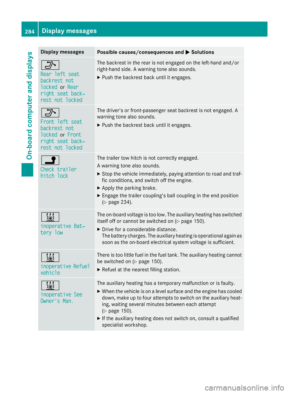
Display messages
Possible causes/consequences and
M
MSolutions _
Rear left seat Rear left seat
backrest not backrest not
locked locked
orRear
Rear
right seat back‐
right seat back‐
rest not locked rest not locked The backrest in the rear is not engaged on the left-hand and/or
right-hand side. A warning tone also sounds.
X Push the backrest back until it engages. _
Front left seat Front left seat
backrest not backrest not
locked locked
orFront
Front
right seat back‐
right seat back‐
rest not locked rest not locked The driver's or front-passenger seat backrest is not engaged. A
warning tone also sounds.
X Push the backrest back until it engages. j
Check trailer Check trailer
hitch lock hitch lock The trailer tow hitch is not correctly engaged.
A warning tone also sounds.
X Stop the vehicle immediately, paying attention to road and traf-
fic conditions, and switch off the engine.
X Apply the parking brake.
X Engage the trailer coupling's ball coupling in the end position
(Y page 234). &
inoperative Bat‐ inoperative Bat‐
tery low tery low The on-board voltage is too low. The auxiliary heating has switched
itself off or cannot be switched on (Y page 150).
X Drive for a considerable distance.
The battery charges. The auxiliary heating is operational again as
soon as the on-board electrical system voltage is sufficient. &
inoperative inoperative
Refuel
Refuel
vehicle
vehicle There is too little fuel in the fuel tank. The auxiliary heating cannot
be switched on (Y page 150).
X Refuel at the nearest filling station. &
inoperative See inoperative See
Owner's Man. Owner's Man. The auxiliary heating has a temporary malfunction or is faulty.
X When the vehicle is on a level surface and the engine has cooled
down, make up to four attempts to switch on the auxiliary heat- ing, waiting several minutes between each attempt
(Y page 150).
X If the auxiliary heating does not switch on, consult a qualified
specialist workshop. 284
Display
messagesOn-board computer and displays
Page 291 of 417
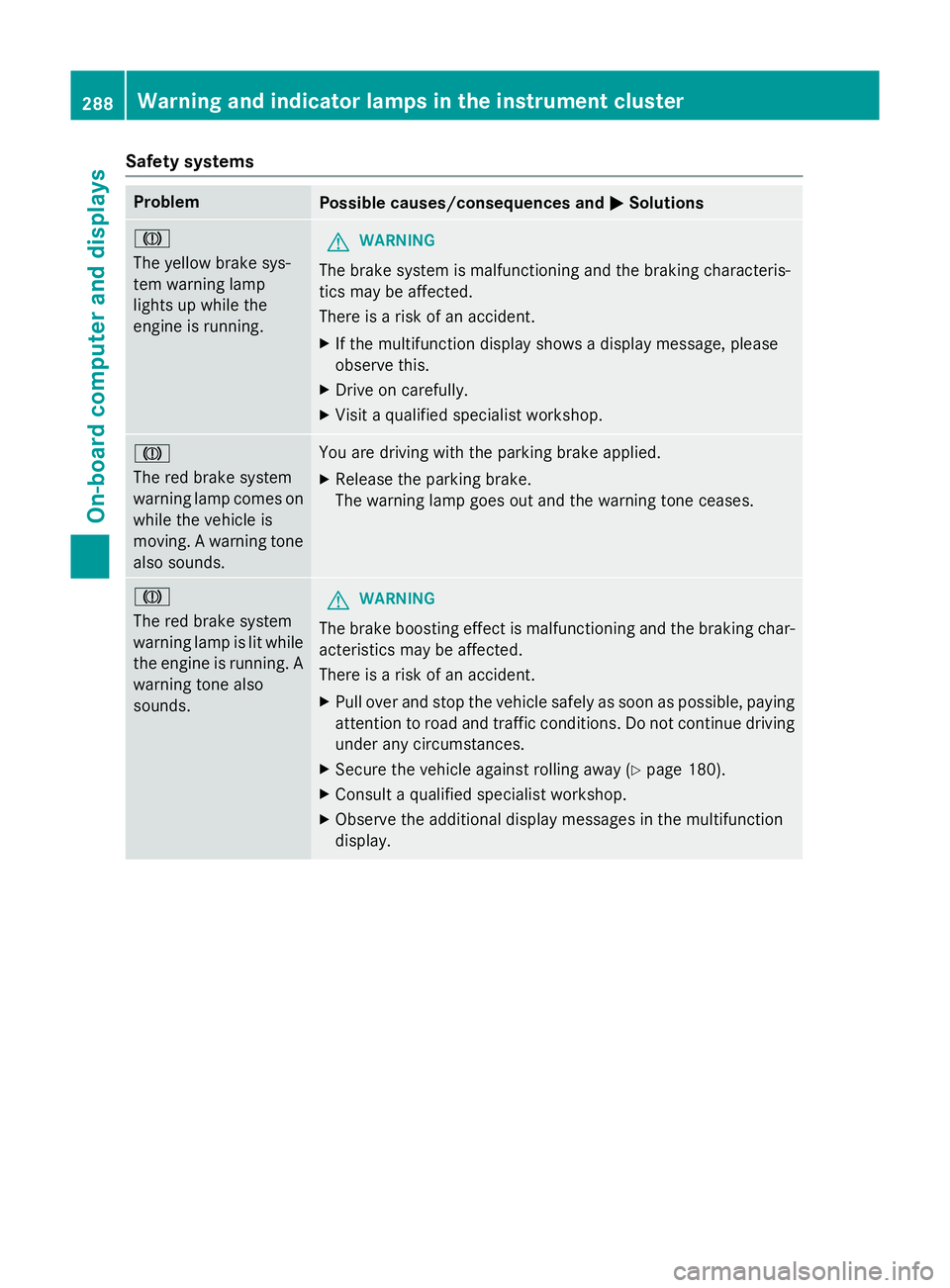
Safety systems
Problem
Possible causes/consequences and
M
MSolutions J
The yellow brake sys-
tem warning lamp
lights up while the
engine is running.
G
WARNING
The brake system is malfunctioning and the braking characteris-
tics may be affected.
There is a risk of an accident.
X If the multifunction display shows a display message, please
observe this.
X Drive on carefully.
X Visit a qualified specialist workshop. J
The red brake system
warning lamp comes on
while the vehicle is
moving. A warning tone
also sounds. You are driving with the parking brake applied.
X Release the parking brake.
The warning lamp goes out and the warning tone ceases. J
The red brake system
warning lamp is lit while
the engine is running. A
warning tone also
sounds. G
WARNING
The brake boosting effect is malfunctioning and the braking char- acteristics may be affected.
There is a risk of an accident.
X Pull over and stop the vehicle safely as soon as possible, paying
attention to road and traffic conditions. Do not continue driving
under any circumstances.
X Secure the vehicle against rolling away (Y page 180).
X Consult a qualified specialist workshop.
X Observe the additional display messages in the multifunction
display. 288
Warning and indicator lamps in the instrument clusterOn-board computer and displays
Page 338 of 417
!
In car washes with a towing mechanism,
make sure that the automatic transmission is in transmission position N, otherwise the
vehicle could be damaged.
R Vehicles with a key:
do not remove the key from the ignition
lock. Do not open the driver's door or
front-passenger door when the engine is
switched off. Otherwise, the automatic
transmission selects park position P
automatically and locks the wheels. You
can prevent this by shifting the auto-
matic transmission to Nbeforehand.
R Vehicles with KEYLESS-GO:
do not open the driver's door or front-
passenger door when the engine is
switched off. Otherwise, the automatic
transmission selects park position P
automatically and locks the wheels.
Observe the following to make sure that the
automatic transmission stays in position N:
X Make sure the vehicle is stationary and the
ignition is switched off.
X Turn the key to position 2(Y page 159) in
the ignition lock.
Use the key instead of the Start/Stop but-
ton on vehicles with KEYLESS-GO.
X Depress and hold the brake pedal.
X Shift the automatic transmission to posi-
tion N.
X Release the brake pedal.
X Release the electric parking brake.
X Switch off the ignition and leave the key in
the ignition lock.
You can wash the vehicle in an automatic car
wash from the very start.
Wash off excess dirt before cleaning the vehi-
cle in an automatic car wash.
After using an automatic car wash, wipe off
wax from the windscreen and the wiper
blades. This will prevent smears and reduce
wiping noises caused by residue on the wind- screen. Washing by hand In some countries, washing by hand is only
allowed at specially equipped washing bays.
Observe the legal requirements for each indi- vidual country.
X Do not use hot water and do not wash the
vehicle in direct sunlight.
X Use a soft sponge to clean.
X Use a mild cleaning agent, such as a car
shampoo approved by Mercedes-Benz.
X Thoroughly hose down the vehicle with a
gentle jet of water.
X Do not point the water jet directly towards
the air inlet.
X Use plenty of water and rinse out the
sponge frequently.
X Rinse the vehicle with clean water and dry
thoroughly with a chamois.
X Do not let the cleaning agent dry on the
paintwork.
When using the vehicle in winter, remove all
traces of road salt deposits carefully and as
soon as possible.
High-pressure cleaning equipment G
WARNING
The water jet of circular-jet nozzles (dirt grind- ers) can cause damage not visible from the
outside to tyres or chassis components. Com-
ponents damaged in this way can unexpect-
edly fail. There is a risk of an accident.
Do not use high-pressure cleaners with circu-
lar-jet nozzles to clean the vehicle. Have dam- aged tyres or chassis components replaced
immediately.
! Always maintain a distance of at least
30 cm between the vehicle and the high-
pressure cleaner nozzle. Information about
the correct distance is available from the
equipment manufacturer.
Move the high-pressure cleaner nozzle
around when cleaning your vehicle. Care
335Maintenance and care Z
Page 359 of 417
R
Jump-starting may only be performed using batteries with a nominal voltage of 12 V.
R Only use jump leads that have a sufficient cross-section and insulated terminal clamps.
R If the battery is fully discharged, leave the battery that is being used to jump-start connected
for a few minutes before attempting to start. This charges the empty battery a little.
R Make sure that the two vehicles do not touch.
Make sure that:
R The jump leads are not damaged.
R Non-insulated parts of the terminal clamps do not come into contact with other metal parts
while the jump leads are connected to the battery.
R The jump leads cannot come into contact with parts which can move when the engine is
running, such as the V-belt pulley or the fan.
X Firmly depress the parking brake.
X Shift the transmission to position P.
X Switch off all electrical consumers, e.g. rear window heating, lighting etc.
X Open the bonnet.
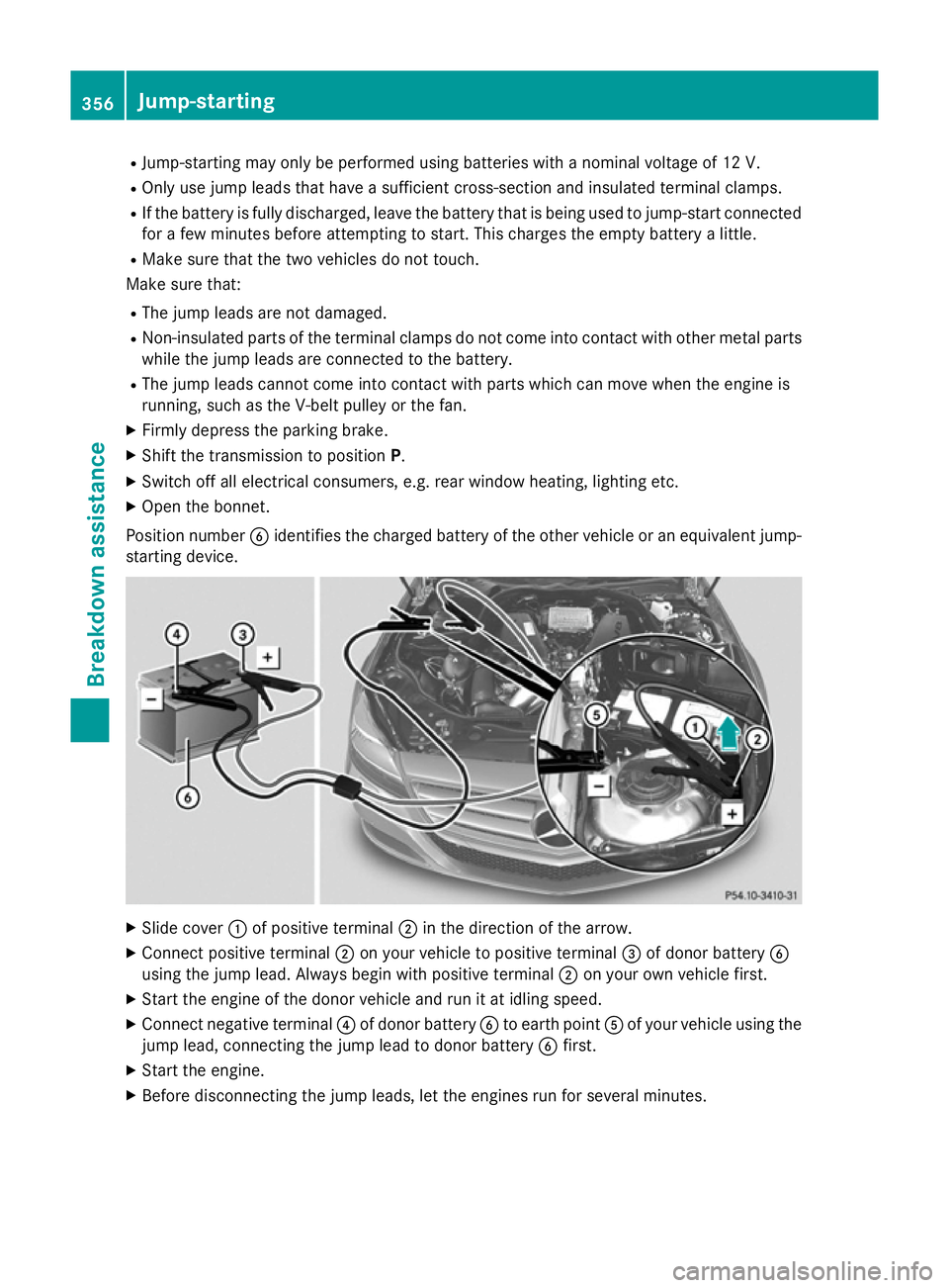
Position number Bidentifies the charged battery of the other vehicle or an equivalent jump-
starting device. X
Slide cover :of positive terminal ;in the direction of the arrow.
X Connect positive terminal ;on your vehicle to positive terminal =of donor battery B
using the jump lead. Always begin with positive terminal ;on your own vehicle first.
X Start the engine of the donor vehicle and run it at idling speed.
X Connect negative terminal ?of donor battery Bto earth point Aof your vehicle using the
jump lead, connecting the jump lead to donor battery Bfirst.
X Start the engine.
X Before disconnecting the jump leads, let the engines run for several minutes. 356
Jump-startingBreakdown assistance
Page 362 of 417
The mountings for the removable towing eyes
are located in the bumpers. They are at the
front and at the rear under the covers.
X Remove the towing eye from the vehicle
tool kit (Y page 345).
X Pull cover :out of the bumper in the
direction of the arrow by inserting your fin-
gers into the recess.
X Press the mark on cover ;inwards in the
direction of the arrow.
X Remove cover ;from the opening.
X Screw the towing eye in clockwise to the
stop and tighten it.
Removing the towing eye X
Loosen the towing eye and unscrew it.
X Position cover :on top of the bumper and
press it in at the bottom until it engages.
X Attach cover ;to the bumper and press
until it engages.
X Place the towing eye in the vehicle tool kit. Towing the vehicle with the rear axle
raised
! The ignition must be switched off if you
are towing the vehicle with the rear axle
raised. Intervention by ESP ®
could other-
wise damage the brake system.
Only possible on vehicles without
4MATIC.
X Switch on the hazard warning lamps
(Y page 126).
X Turn the key in the ignition lock to position
0 and remove the key from the ignition
lock.
X When leaving the vehicle, take the key or
the KEYLESS-GO key with you.
When towing your vehicle with the rear axle
raised, it is important that you observe the
safety instructions (Y page 357). Towing the vehicle with both axles on
the ground
It is important that you observe the safety
instructions when towing away your vehicle
(Y page 357).
The automatic transmission automatically
shifts to position Pwhen you open the driver's
or front-passenger door or when you remove the key from the ignition lock. In order to
ensure that the automatic transmission stays
in position Nwhen towing the vehicle, you
must observe the following points:
X Make sure that the vehicle is stationary and
that the key is in position 0in the ignition
lock.
X Turn the key to position 2in the ignition
lock.
On vehicles with KEYLESS-GO, use the key instead of the Start/Stop button
(Y page 159).
X Depress and hold the brake pedal.
X Shift the automatic transmission to posi-
tion N.
X Release the brake pedal.
X Release the parking brake.
X Switch on the hazard warning lamps
(Y page 126).
X Leave the key in position 2in the ignition
lock.
i When towing with the hazard warning
lamps switched on, use the combination
switch as usual to signal a change of direc- tion. In this case, only the turn signals for
the desired direction flash. When you reset
the combination switch, the hazard warn-
ing lamps start flashing again. Transporting the vehicle
! You may only secure the vehicle by the
wheels, not by parts of the vehicle such as
axle or steering components. Otherwise,
the vehicle could be damaged. Towing and tow-starting
359Breakdown assistance Z
Page 363 of 417
The towing eye can be used to pull the vehicle
onto a trailer or transporter for transporta-
tion.
The towing eyes or trailer tow hitch can be
used to pull the vehicle onto a trailer or trans-
porter if you wish to transport it.
X Turn the key to position 2in the ignition
lock.
X Shift the automatic transmission to posi-
tion N.
As soon as the vehicle is loaded:
X Prevent the vehicle from rolling away by
applying the parking brake.
X Shift the automatic transmission to posi-
tion P.
X Turn the key in the ignition lock to position
0 and remove the key from the ignition
lock.
X Secure the vehicle. Notes for 4MATIC vehicles
! Vehicles with 4MATIC must not be towed
with the front or rear axle raised; otherwise,
the transmission may be damaged.
If the vehicle has transmission damage or
damage to the front or rear axle, have it trans- ported on a transporter or trailer.
In the event of damage to the electrical
system
If the battery is defective, the automatic
transmission will be locked in position P. To
shift the automatic transmission to position
N, you must provide power to the vehicle's
electrical system in the same way as when
jump-starting (Y page 355).
Have the vehicle transported on a transporter
or trailer. Tow-starting (emergency engine
starting)
! Vehicles with automatic transmission
must not be tow-started. The transmission
may otherwise be damaged.
i You can find information on "Jump-start-
ing" under (Y page 355). Electrical fuses
Important safety notes
G
WARNING
If you manipulate, bridge or replace a faulty
fuse with a fuse of a higher amperage, the
electric cables could be overloaded. This may result in a fire. There is a risk of an accident
and injury.
Always replace faulty fuses with specified new fuses of the correct amperage.
! Only use fuses that have been approved
for Mercedes-Benz vehicles and which
have the correct fuse rating for the system concerned. Otherwise, components or sys-
tems could be damaged.
The fuses in your vehicle serve to disconnect
faulty circuits. If a fuse blows, all the compo- nents on the circuit and their functions will
fail.
Blown fuses must be replaced with fuses of
the same rating, which you can recognise by
the colour and fuse rating. The fuse ratings
are listed in the fuse allocation chart.
If the newly inserted fuse also blows, have the
cause traced and rectified at a qualified spe-
cialist workshop, e.g. a Mercedes-Benz Ser-
vice Centre. Before replacing a fuse
Observe the important safety notes
(Y page 360) 360
Electrical fusesBreakdown assistance
Page 377 of 417
Interchanging the front and rear wheels of
differing dimensions can render the general
operating permit invalid.
Observe the instructions and safety notes in
the "Fitting a wheel" section (Y page 374).
The wear patterns on the front and rear tyres differ depending on the operating conditions.Interchange the wheels before a clear wear
pattern has formed on the tyres. Front tyres
typically wear more on the shoulders and the
rear tyres in the centre.
On vehicles that have the same size front and rear wheels, you can interchange the wheels
every 5,000 to 10,000 km depending on the
degree of tyre wear. Ensure that the direction
of rotation is maintained.
Clean the contact surfaces of the wheel and
the brake disc thoroughly every time a wheel
is interchanged. Check the tyre pressure and, if necessary, restart the tyre pressure loss
warning system or the tyre pressure monitor. Direction of rotation
Tyres with a specified direction of rotation
have additional benefits, e.g. if there is a risk of aquaplaning. You will only gain these ben-
efits if the correct direction of rotation is
observed.
An arrow on the sidewall of the tyre indicates
its correct direction of rotation. Storing wheels
Store wheels that are not being used in a cool,
dry and preferably dark place. Protect the
tyres against oil, grease, petrol and diesel. Cleaning the wheels
G
WARNING
The water jet of circular-jet nozzles (dirt grind- ers) can cause damage not visible from the
outside to tyres or chassis components. Com- ponents damaged in this way can unexpect-
edly fail. There is a risk of an accident.
Do not use high-pressure cleaners with circu- lar-jet nozzles to clean the vehicle. Have dam-aged tyres or chassis components replaced
immediately. Fitting a wheel
Preparing the vehicle X
Stop the vehicle on solid, non-slippery and
level ground.
X Apply the parking brake.
X Move the front wheels to the straight-
ahead position.
X Shift the transmission to position P.
X Vehicles with AIRMATIC: make sure that
"normal" vehicle level is selected
(Y page 202).
X Switch off the engine.
X Vehicles without KEYLESS-GO: remove
the key from the ignition lock.
X Vehicles with KEYLESS-GO: open the
driver's door.
The on-board electronics now have status
0. This is the same as the key having been
removed.
X Vehicles with KEYLESS-GO: remove the
Start/Stop button from the ignition lock
(Y page 159).
X If included in the vehicle equipment,
remove the tyre-change tool kit from the
vehicle (Y page 345).
X Secure the vehicle to prevent it from rolling
away.
i Apart from some country-specific var-
iants, vehicles are not equipped with tyre-
changing tools. Some tools for changing a
wheel are specific to the vehicle. For more information on which tools are required to
perform a wheel change on your vehicle,
consult a qualified specialist workshop. 374
Changing a wheelWheels and tyres
Page 379 of 417

R
before raising the vehicle, secure it from
rolling away by applying the parking brake
and positioning wheel chocks. Never
release the parking brake while the vehicle
is raised.
R the jack must be placed on a firm, flat and
non-slip surface. On a loose surface, a
large, flat load-bearing underlay must be
used. On a slippery surface, a non-slip
underlay must be used, e.g. rubber mats.
R do not use wooden blocks or similar
objects as a jack underlay. Otherwise, the
jack will not be able to achieve its load-
bearing capacity due to the restricted
height.
R make sure that the distance between the
underside of the tyres and the ground does
not exceed 3 cm.
R never place your hands or feet under the
raised vehicle.
R do not lie under the vehicle.
R do not start the engine when the vehicle is
raised.
R do not open or close a door or the boot lid/
tailgate when the vehicle is raised.
R make sure that no persons are present in
the vehicle when the vehicle is raised. X
Using wheel wrench :, loosen the bolts on
the wheel you wish to change by about one full turn. Do not unscrew the bolts com-
pletely. Jacking points (example: CLS Coupé)
X
Position jack =at jacking point ;. Example
X Make sure that the base of the jack is posi-
tioned vertically under the jacking point.
X Turn crank ?clockwise until jack =sits
completely on jacking point ;and the
base of the jack lies evenly on the ground.
X Turn crank ?until the tyre is raised a max-
imum of 3 cm off the ground. 376
Changing a wheelWheels and tyres