2014 MERCEDES-BENZ CLS COUPE change time
[x] Cancel search: change timePage 259 of 417
Heating
Auxiliary heating departure time
G
DANGER
If the exhaust pipe is blocked or sufficient
ventilation is not possible, toxic exhaust
fumes can enter the vehicle, especially car-
bon monoxide. This is the case, e.g. in
enclosed spaces, or if the vehicle is stuck in
snow. There is a risk of fatal injuries.
You should switch off the auxiliary heating in
enclosed spaces which do not have an extrac- tion system, e.g. a garage. If the vehicle is
stuck in snow and you must leave the auxiliary
heating running, keep the exhaust pipe and
the area around the vehicle clear of snow. To guarantee a sufficient supply of fresh air, open
a window on the side of the vehicle away from the wind. G
WARNING
When the auxiliary heating is switched on,
parts of the vehicle can become very hot.
Flammable materials such as leaves, grass or twigs may ignite if they come into contact
with:
R hot parts of the exhaust system
R the exhaust gas itself
There is a risk of fire.
When the auxiliary heating is switched on,
make sure that:
R no flammable materials come into contact
with hot vehicle components
R the exhaust gas can escape from the
exhaust pipe unhindered
R the exhaust gas does not come into contact
with flammable materials.
! Operating the auxiliary heating/ventila-
tion draws on the vehicle battery. After you
have heated or ventilated the vehicle a
maximum of two times, drive for a longer
distance.
Only vehicles with auxiliary heating have this
function (Y page 150). In the
Heating
Heating submenu, you can select a
stored departure time or change a departure
time.
The auxiliary heating timer function calcu-
lates the switch-on time according to the out-
side temperature so that the vehicle is pre-
heated by the departure time. When the
departure time is reached, the auxiliary heat- ing continues to heat for a further five
minutes and then switches off. The auxiliary
heating adopts the THERMATIC or
THERMOTRONIC temperature setting.
You can switch off the auxiliary heating by
using the remote control or the auxiliary heat- ing button on the centre console.
i Switch the auxiliary heating on regularly
once a month for about ten minutes.
Selecting the departure time or deactivat-
ing a selected departure time
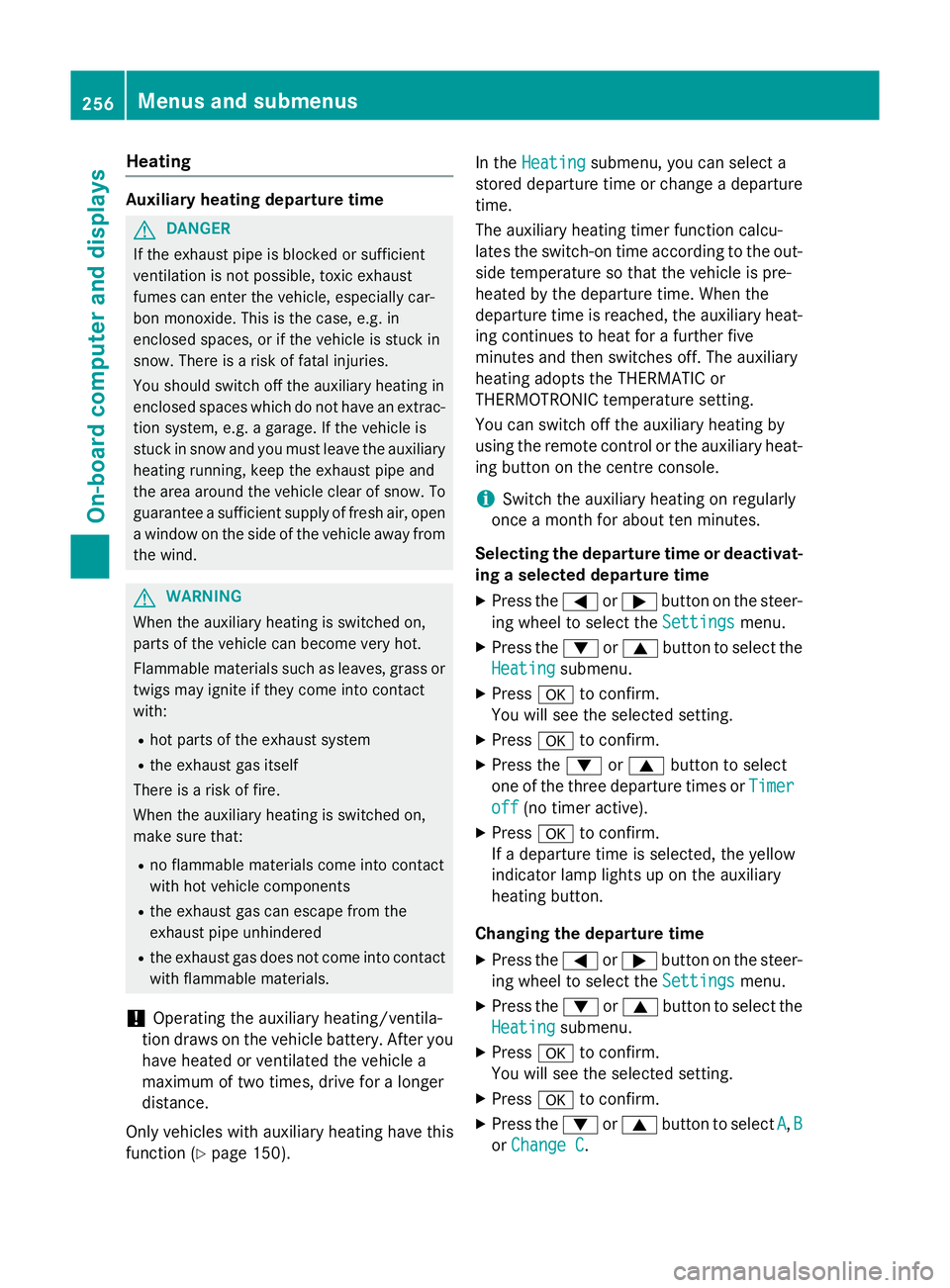
X Press the =or; button on the steer-
ing wheel to select the Settings
Settings menu.
X Press the :or9 button to select the
Heating Heating submenu.
X Press ato confirm.
You will see the selected setting.
X Press ato confirm.
X Press the :or9 button to select
one of the three departure times or Timer
Timer
off
off (no timer active).
X Press ato confirm.
If a departure time is selected, the yellow
indicator lamp lights up on the auxiliary
heating button.
Changing the departure time
X Press the =or; button on the steer-
ing wheel to select the Settings Settingsmenu.
X Press the :or9 button to select the
Heating
Heating submenu.
X Press ato confirm.
You will see the selected setting.
X Press ato confirm.
X Press the :or9 button to select A
A,B
B
or Change C
Change C. 256
Menus and submenusOn-board computer and displays
Page 260 of 417
X
Press ato confirm.
You can now change the departure time.
X Press the =or; button to select the
display to be changed: hours, minutes.
X Press the :or9 button to set the
selected display.
X Press the abutton to store the entry.
The yellow indicator lamp on the auxiliary
heating button lights up.
Comfort Activating/deactivating the EASY-
ENTRY/EXIT feature
G
WARNING
When the EASY-ENTRY/EXIT feature adjusts
the steering wheel, you and other vehicle
occupants – particularly children – could
become trapped. There is a risk of injury.
While the EASY-ENTRY/EXIT feature is mak-
ing adjustments, make sure that no one has
any body parts in the sweep of the steering
wheel.
If someone is trapped:
R press one of the memory function position
buttons, or
R move the switch for steering wheel adjust-
ment in the opposite direction to that in
which the steering wheel is moving.
The adjustment process is stopped.
X Press the =or; button on the steer-
ing wheel to select the Settings
Settings menu.
X Press the :or9 button to select the
Convenience
Convenience submenu.
X Press ato confirm.
X Press the :or9 button to select the
Easy Entry/Exit: Easy Entry/Exit: function.
If the Easy Entry/Exit
Easy Entry/Exit function is activa-
ted, the vehicle steering wheel is displayed
in orange in the multifunction display.
X Press the abutton to save the setting.
Further information on the EASY-ENTRY/EXIT feature (Y page 115). Switching belt adjustment on/off
X Press the =or; button on the steer-
ing wheel to select the Settings
Settings menu.
X Press the :or9 button to select the
Convenience
Convenience submenu.
X Press ato confirm.
X Press the :or9 button to select the
Belt adjustment
Belt adjustment function.
If the Belt adjustment
Belt adjustment function is activa-
ted, the vehicle seat belt is shown in orange
in the multifunction display.
X Press the abutton to save the setting.
For further information on belt adjustment,
see (Y page 47).
Switching the fold-in mirrors when lock-
ing function on/off
This function is only available on vehicles with
a memory function (Y page 119).
When you switch on the Auto. fold in
Auto. fold in
function, the exterior mirrors are folded in
when the vehicle is locked. When you unlock
the vehicle and then open a door, the exterior mirrors fold out again.
X Press the =or; button on the steer-
ing wheel to select the Settings Settingsmenu.
X Press the :or9 button to select the
Convenience
Convenience submenu.
X Press ato confirm.
X Press the :or9 button to select the
Auto. fold in
Auto. fold in function.
If the Auto.
Auto. fold
foldin
infunction is switched
on, the vehicle's exterior mirror is displayed
in orange in the multifunction display.
X Press the abutton to save the setting. Menus and submenus
257On-board computer and displays Z
Page 336 of 417
Maintaining the time-dependent service
schedule:
X Note down the service due date displayed
in the multifunction display before discon-
necting the battery.
or X After reconnecting the battery, subtract
the battery disconnection periods from the service date shown on the display.
Hiding service messages X
Press the aor% button on the steer-
ing wheel.
Displaying service messages X
Switch the ignition on.
X Press the =or; button on the steer-
ing wheel to select the Service
Service menu.
X Press the 9or: button to select the
ASSYST PLUS
ASSYST PLUS submenu and confirm by
pressing the abutton.
The service due date appears in the multi-
function display.
Information about Service Resetting the ASSYST PLUS service inter-
val display
! If the ASSYST PLUS service interval dis-
play has been inadvertently reset, this set-
ting can be corrected at a qualified special-
ist workshop.
Have service work carried out as described in the Service Booklet. This may otherwise
lead to increased wear and damage to the
major assemblies or the vehicle.
A qualified specialist workshop, e.g. a
Mercedes-Benz Service Centre, will reset the ASSYST PLUS service interval display after
the service work has been carried out. You
can also obtain further information on main-
tenance work, for example. Special service requirements
The prescribed service interval is based on
normal operation of the vehicle. Service work
will need to be performed more often if the
vehicle is operated under arduous conditions or increased loads, for example:
R regular city driving with frequent intermedi-
ate stops
R if the vehicle is primarily used to travel
short distances
R for frequent operation in mountainous ter-
rain or on poor road surfaces
R if the engine is often left idling for long peri-
ods
In these or similar operating conditions, have,
for example, the air filter, engine oil and oil
filter changed more frequently. The tyres
must be checked more frequently if the vehi-
cle is operated under increased loads. Fur-
ther information can be obtained at a quali-
fied specialist workshop, e.g. a Mercedes-
Benz Service Centre.
Driving abroad
An extensive Mercedes-Benz Service network is also available in other countries. You can
obtain further information from any
Mercedes-Benz Service Centre. AdBlue
®
service indicator
i For BlueTEC vehicles only.
To function properly, BlueTEC exhaust gas
aftertreatment must be operated with the
reducing agent AdBlue ®
. AdBlue ®
is topped
up as part of the service. Under normal oper-
ating conditions, a full tank of AdBlue ®
should
last until the next service due date.
Depending on how and where the vehicle is
used, there may be an increase in the
AdBlue ®
consumption, resulting in the next
service due date being brought forward.
Certain display messages show that AdBlue ®
must be topped up, e.g.: Service
333Maintenance and care Z
Page 352 of 417
R
Immediately change out of clothing which
has come into contact with tyre sealant.
R If an allergic reaction occurs, seek medical
attention immediately.
! Do not operate the tyre inflation com-
pressor for longer than eight minutes at a
time without a break. It may otherwise
overheat.
The tyre inflation compressor can be oper-
ated again once it has cooled down.
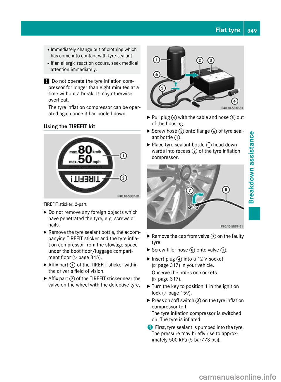
Using the TIREFIT kit TIREFIT sticker, 2-part
X Do not remove any foreign objects which
have penetrated the tyre, e.g. screws or
nails.
X Remove the tyre sealant bottle, the accom-
panying TIREFIT sticker and the tyre infla-
tion compressor from the stowage space
under the boot floor/luggage compart-
ment floor (Y page 345).
X Affix part :of the TIREFIT sticker within
the driver's field of vision.
X Affix part ;of the TIREFIT sticker near the
valve on the wheel with the defective tyre. X
Pull plug ?with the cable and hose Aout
of the housing.
X Screw hose Aonto flange Bof tyre seal-
ant bottle :.
X Place tyre sealant bottle :head down-
wards into recess ;of the tyre inflation
compressor. X
Remove the cap from valve Con the faulty
tyre.
X Screw filler hose Donto valve C.
X Insert plug ?into a 12 V socket
(Y page 317) in your vehicle.
Observe the notes on sockets
(Y page 317).
X Turn the key to position 1in the ignition
lock (Y page 159).
X Press on/off switch =on the tyre inflation
compressor to I.
The tyre inflation compressor is switched
on. The tyre is inflated.
i First, tyre sealant is pumped into the tyre.
The pressure may briefly rise to approx-
imately 500 kPa (5 bar/73 psi). Flat tyre
349Breakdown assistance Z
Page 372 of 417
10 kPa (0.1 bar/1.5 psi) per 10 †. Take this
into account when checking the pressure of
warm tyres. Only correct the tyre pressure if it
is too low for the current operating condi-
tions.
Driving with tyre pressure that is too high or
too low can:
R shorten the service life of the tyres
R cause increased tyre damage
R have a negative effect on handling charac-
teristics and thus driving safety (e.g. aqua-
planing)
i The tyre pressure values given for low
loads are minimum values which offer you
good ride comfort characteristics.
However, you can also use the values given for higher loads. These are permissible and
will not adversely affect the running of the
vehicle.
For speeds up to 210 km/h (does not
apply to AMG vehicles): for speeds up to
210 km/h, the values given on the tyre pres- sure information label (fuel filler flap) may be
reduced by 20 kPa (0.2 bar/3 psi) without a
reduction in safety.
This improves the ride comfort of your vehi-
cle; however, fuel consumption may increase
slightly. Tyre pressure loss warning system
General notes While the vehicle is in motion, the tyre pres-
sure loss warning system monitors the set
tyre pressure using the rotational speed of
the wheels. This enables the system to detect significant pressure loss in a tyre. If the speed
of rotation of a wheel changes as a result of a loss of pressure, a corresponding warning
message will appear in the multifunction dis- play.
You can recognise the tyre pressure loss
warning by the Run Flat Indicator
Run Flat Indicator
active Restart with OK active Restart with OK message whichappears in the
Serv.
Serv.menu of the multifunc-
tion display. Information on the message dis- play can be found in the "Restarting the tyre
pressure loss warning system" section
(Y page 369).
Important safety notes The tyre pressure warning system does not
warn you of an incorrectly set tyre pressure.
Observe the notes on the recommended tyre
pressure (Y page 367).
The tyre pressure loss warning does not
replace the need to regularly check the tyre
pressures. An even loss of pressure on sev-
eral tyres at the same time cannot be detec-
ted by the tyre pressure loss warning system.
The tyre pressure monitor is not able to warn you of a sudden loss of pressure, e.g. if the
tyre is penetrated by a foreign object. In the
event of a sudden loss of pressure, bring the
vehicle to a halt by braking carefully. Avoid
abrupt steering manoeuvres.
The function of the tyre pressure loss warning
system is limited or delayed if:
R snow chains are fitted to your vehicle's
tyres
R road conditions are wintry
R you are driving on sand or gravel
R you adopt a very sporty driving style (cor-
nering at high speeds or driving with high
rates of acceleration)
R you are towing a very heavy or large trailer
R you are driving with a heavy load (in the
vehicle or on the roof)
Restarting the tyre pressure loss warn-
ing system Restart the tyre pressure loss warning system
if you have:
R changed the tyre pressure
R changed the wheels or tyres
R fitted new wheels or tyres
X Before restarting, make sure that the tyre
pressures are set properly on all four tyres Tyre pressure
369Wheels and tyres Z
Page 375 of 417
Warning messages of the tyre pressure
monitor If the tyre pressure monitor detects a pres-
sure loss in one or more tyres, a warning mes-
sage is shown in the multifunction display and the yellow tyre pressure monitor warning
lamp comes on.
R If the Please correct tyre pressure
Please correct tyre pressure
message appears in the multifunction dis-
play, the tyre pressure in at least one tyre is too low and must be corrected at the next
opportunity.
R If the Check tyre(s) Check tyre(s) message appears in
the multifunction display, the tyre pressure
in one or more tyres has dropped signifi-
cantly and the tyres must be checked.
R If the Warning tyre defect
Warning tyre defect message
appears in the multifunction display, the
tyre pressure in one or more tyres has drop-
ped suddenly and the tyres must be
checked.
Observe the instructions and safety notes in
the display messages in the "Tyres" section
(Y page 280).
i If the wheel positions on the vehicle are
interchanged, the tyre pressures may be
displayed for the wrong positions for a
short time. After a few minutes of driving,
this is rectified and the tyre pressures are
displayed for the correct positions.
Restarting the tyre pressure monitor When you restart the tyre pressure monitor,
all existing warning messages are deleted and
the warning lamps go out. The monitor uses
the currently set tyre pressures as the refer-
ence values for monitoring. In most cases, the tyre pressure monitor will automatically
detect the new reference values after you
have changed the tyre pressure. However,
you can also define reference values man-
ually as described here. The tyre pressure
monitor then monitors the new tyre pressure
values. X
Using the table on the inside of the fuel filler
flap, ensure that the tyre pressure is set
correctly in all four tyres for the current
operating conditions.
Also observe the notes in the section on
tyre pressures (Y page 367).
X Make sure that the key is in position 2in the
ignition lock.
X Press the =or; button on the steer-
ing wheel to select the Service Servicemenu.
X Press the 9or: button to select
Tyre pressure
Tyre pressure.
X Press the abutton.
The multifunction display shows the cur-
rent tyre pressure for the individual tyres or
the Tyre pressures will be dis‐ Tyre pressures will be dis‐
played
played after
aftera
afew
few minutes
minutes of
ofdriv‐
driv‐
ing
ing message.
X Press the :button.
The Use current pressures as new Use current pressures as new
reference values reference values message appears in
the multifunction display.
If you wish to confirm the restart: X Press the abutton.
The Tyre press. monitor restarted
Tyre press. monitor restarted
message appears in the multifunction dis-
play.
After you have driven for a few minutes, the system checks whether the current tyre
pressures are within the specified range.
The new tyre pressures are then accepted
as reference values and monitored.
If you wish to cancel the restart:
X Press the %button.
The tyre pressure values stored at the last
restart will continue to be monitored. 372
Tyre pressureWheels and tyres
Page 377 of 417
Interchanging the front and rear wheels of
differing dimensions can render the general
operating permit invalid.
Observe the instructions and safety notes in
the "Fitting a wheel" section (Y page 374).
The wear patterns on the front and rear tyres differ depending on the operating conditions.Interchange the wheels before a clear wear
pattern has formed on the tyres. Front tyres
typically wear more on the shoulders and the
rear tyres in the centre.
On vehicles that have the same size front and rear wheels, you can interchange the wheels
every 5,000 to 10,000 km depending on the
degree of tyre wear. Ensure that the direction
of rotation is maintained.
Clean the contact surfaces of the wheel and
the brake disc thoroughly every time a wheel
is interchanged. Check the tyre pressure and, if necessary, restart the tyre pressure loss
warning system or the tyre pressure monitor. Direction of rotation
Tyres with a specified direction of rotation
have additional benefits, e.g. if there is a risk of aquaplaning. You will only gain these ben-
efits if the correct direction of rotation is
observed.
An arrow on the sidewall of the tyre indicates
its correct direction of rotation. Storing wheels
Store wheels that are not being used in a cool,
dry and preferably dark place. Protect the
tyres against oil, grease, petrol and diesel. Cleaning the wheels
G
WARNING
The water jet of circular-jet nozzles (dirt grind- ers) can cause damage not visible from the
outside to tyres or chassis components. Com- ponents damaged in this way can unexpect-
edly fail. There is a risk of an accident.
Do not use high-pressure cleaners with circu- lar-jet nozzles to clean the vehicle. Have dam-aged tyres or chassis components replaced
immediately. Fitting a wheel
Preparing the vehicle X
Stop the vehicle on solid, non-slippery and
level ground.
X Apply the parking brake.
X Move the front wheels to the straight-
ahead position.
X Shift the transmission to position P.
X Vehicles with AIRMATIC: make sure that
"normal" vehicle level is selected
(Y page 202).
X Switch off the engine.
X Vehicles without KEYLESS-GO: remove
the key from the ignition lock.
X Vehicles with KEYLESS-GO: open the
driver's door.
The on-board electronics now have status
0. This is the same as the key having been
removed.
X Vehicles with KEYLESS-GO: remove the
Start/Stop button from the ignition lock
(Y page 159).
X If included in the vehicle equipment,
remove the tyre-change tool kit from the
vehicle (Y page 345).
X Secure the vehicle to prevent it from rolling
away.
i Apart from some country-specific var-
iants, vehicles are not equipped with tyre-
changing tools. Some tools for changing a
wheel are specific to the vehicle. For more information on which tools are required to
perform a wheel change on your vehicle,
consult a qualified specialist workshop. 374
Changing a wheelWheels and tyres
Page 378 of 417
Necessary wheel-changing tools may
include, for example:
R jack
R wheel chock
R wheel wrench
Securing the vehicle against rolling
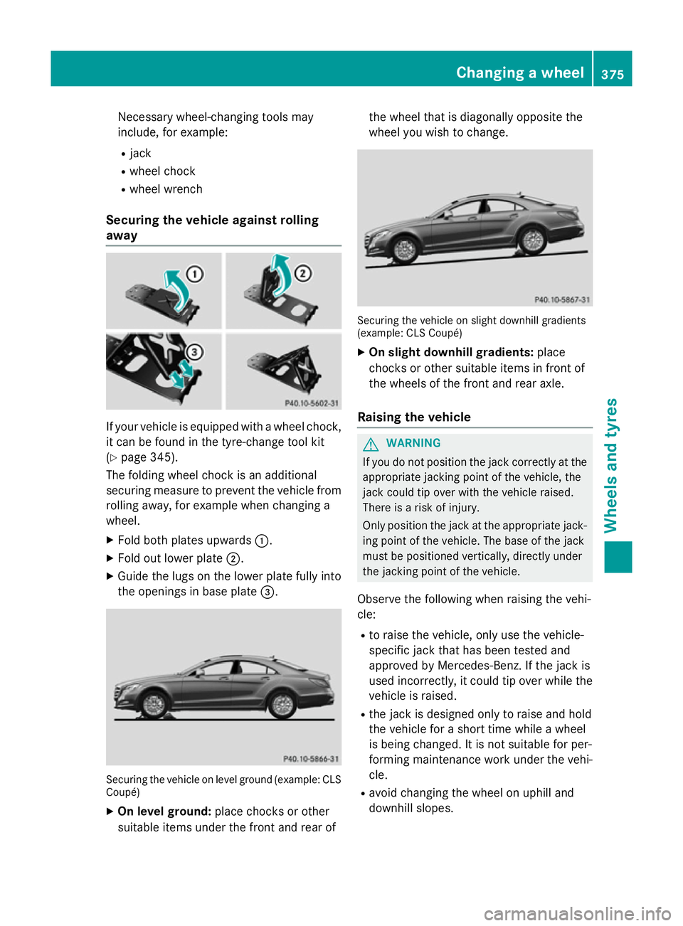
away If your vehicle is equipped with a wheel chock,
it can be found in the tyre-change tool kit
(Y page 345).
The folding wheel chock is an additional
securing measure to prevent the vehicle from rolling away, for example when changing a
wheel.
X Fold both plates upwards :.
X Fold out lower plate ;.
X Guide the lugs on the lower plate fully into
the openings in base plate =.Securing the vehicle on level ground (example: CLS
Coupé)
X On level ground: place chocks or other
suitable items under the front and rear of the wheel that is diagonally opposite the
wheel you wish to change.
Securing the vehicle on slight downhill gradients
(example: CLS Coupé)
X On slight downhill gradients: place
chocks or other suitable items in front of
the wheels of the front and rear axle.
Raising the vehicle G
WARNING
If you do not position the jack correctly at the appropriate jacking point of the vehicle, the
jack could tip over with the vehicle raised.
There is a risk of injury.
Only position the jack at the appropriate jack-
ing point of the vehicle. The base of the jack
must be positioned vertically, directly under
the jacking point of the vehicle.
Observe the following when raising the vehi-
cle: R to raise the vehicle, only use the vehicle-
specific jack that has been tested and
approved by Mercedes-Benz. If the jack is
used incorrectly, it could tip over while the vehicle is raised.
R the jack is designed only to raise and hold
the vehicle for a short time while a wheel
is being changed. It is not suitable for per-
forming maintenance work under the vehi-
cle.
R avoid changing the wheel on uphill and
downhill slopes. Changing a wheel
375Wheels and tyres Z