2014 MERCEDES-BENZ CLS COUPE ignition
[x] Cancel search: ignitionPage 352 of 417
R
Immediately change out of clothing which
has come into contact with tyre sealant.
R If an allergic reaction occurs, seek medical
attention immediately.
! Do not operate the tyre inflation com-
pressor for longer than eight minutes at a
time without a break. It may otherwise
overheat.
The tyre inflation compressor can be oper-
ated again once it has cooled down.
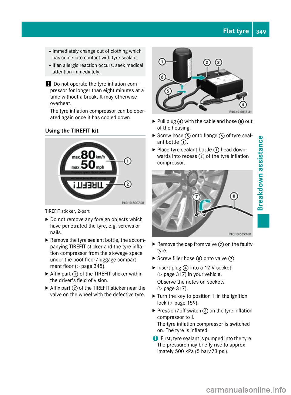
Using the TIREFIT kit TIREFIT sticker, 2-part
X Do not remove any foreign objects which
have penetrated the tyre, e.g. screws or
nails.
X Remove the tyre sealant bottle, the accom-
panying TIREFIT sticker and the tyre infla-
tion compressor from the stowage space
under the boot floor/luggage compart-
ment floor (Y page 345).
X Affix part :of the TIREFIT sticker within
the driver's field of vision.
X Affix part ;of the TIREFIT sticker near the
valve on the wheel with the defective tyre. X
Pull plug ?with the cable and hose Aout
of the housing.
X Screw hose Aonto flange Bof tyre seal-
ant bottle :.
X Place tyre sealant bottle :head down-
wards into recess ;of the tyre inflation
compressor. X
Remove the cap from valve Con the faulty
tyre.
X Screw filler hose Donto valve C.
X Insert plug ?into a 12 V socket
(Y page 317) in your vehicle.
Observe the notes on sockets
(Y page 317).
X Turn the key to position 1in the ignition
lock (Y page 159).
X Press on/off switch =on the tyre inflation
compressor to I.
The tyre inflation compressor is switched
on. The tyre is inflated.
i First, tyre sealant is pumped into the tyre.
The pressure may briefly rise to approx-
imately 500 kPa (5 bar/73 psi). Flat tyre
349Breakdown assistance Z
Page 355 of 417
Before handling the battery, touch the vehicle
body to remove any existing electrostatic
build-up.
The highly flammable gas mixture is created
while the battery is charging and when jump- starting.
Always make sure that neither you nor the
battery is electrostatically charged. Electro-
static charge is created, for example:
R by wearing synthetic fibre clothing
R due to friction between clothing and the
seat
R when you pull or push the battery across
carpet or other synthetic materials
R when you rub the battery with a cloth G
WARNING
During the charging process, a battery produ- ces hydrogen gas. If a short circuit occurs or
sparks are created, the hydrogen gas can
ignite. There is a risk of an explosion.
R Make sure that the positive terminal of a
connected battery does not come into con- tact with vehicle parts.
R Never place metal objects or tools on a bat-
tery.
R It is important that you observe the descri-
bed order of the battery terminals when
connecting and disconnecting a battery.
R When jump-starting, make sure that the
battery poles with identical polarity are
connected.
R It is particularly important to observe the
described order when connecting and dis-
connecting the jump leads.
R Never connect or disconnect the battery
terminals while the engine is running. G
WARNING
Battery acid is caustic. There is a risk of injury. Avoid contact with the skin, eyes or clothing.
Do not inhale any battery gases. Do not lean
over the battery. Keep children away from batteries. Wash battery acid immediately with
water and seek medical attention. H
Environmental note Batteries contain pollutants.
It is illegal to dispose of them
with the household rubbish.
They must be collected sep-
arately and disposed of in anenvironmentally responsible
recycling system. Dispose of batteries in an
environmentally responsible
manner. Take discharged
batteries to a qualified spe-
cialist workshop or to a col-
lection point for used batter-
ies.
! Have the battery checked regularly at a
qualified specialist workshop.
Observe the service intervals in the Service
Booklet or contact a qualified specialist
workshop for more information.
! You should have all work involving the
battery carried out at a qualified specialist
workshop. In the exceptional case that it is
necessary for you to disconnect the battery yourself, make sure that:
R you switch off the engine and remove the
key. On vehicles with KEYLESS-GO,
ensure that the ignition is switched off.
Check that all the indicator lamps in the
instrument cluster are off. Otherwise,
electronic components, such as the
alternator, may be damaged.
R you first remove the negative terminal
clamp and then the positive terminal
clamp. Never swap the terminal clamps.
Otherwise, the vehicle's electronic sys-
tem may be damaged.
R the transmission is locked in position P
after disconnecting the battery. The vehi-
cle is secured against rolling away. You
can then no longer move the vehicle. 352
Battery (vehicle)Breakdown assistance
Page 361 of 417
!
Do not use the towing eye for recovery,
this could damage the vehicle. If in doubt,
recover the vehicle with a crane.
! When towing, pull away slowly and
smoothly. If the tractive power is too high,
the vehicles could be damaged.
! To tow vehicles with KEYLESS-GO, use
the key instead of the Start/Stop button.
The automatic transmission may otherwise switch to position Pwhen you open the
driver's or front-passenger door which
could damage the transmission.
! You may tow the vehicle for a maximum of
50km. A towing speed of 50 km/h must not be exceeded.
For towing distances over 50 km, the entire
vehicle must be lifted up and transported.
! If you tow or tow-start another vehicle, its
weight must not exceed the maximum per- missible gross vehicle weight of your vehi-
cle.
Observe the legal requirements for the rele-
vant countries when towing.
It is better to have the vehicle transported
than to have it towed.
If the vehicle has suffered transmission dam-
age, have it transported on a transporter or
trailer.
The automatic transmission must be in posi-
tion Nwhen the vehicle is being towed.
The battery must be connected and charged. Otherwise, you:
R cannot turn the key in the ignition lock to
position 2
R cannot shift the automatic transmission to
position N
i Deactivate the automatic locking feature
before the vehicle is towed away
(Y page 90). You could otherwise be locked
out when pushing or towing the vehicle.
i Deactivate tow-away protection before
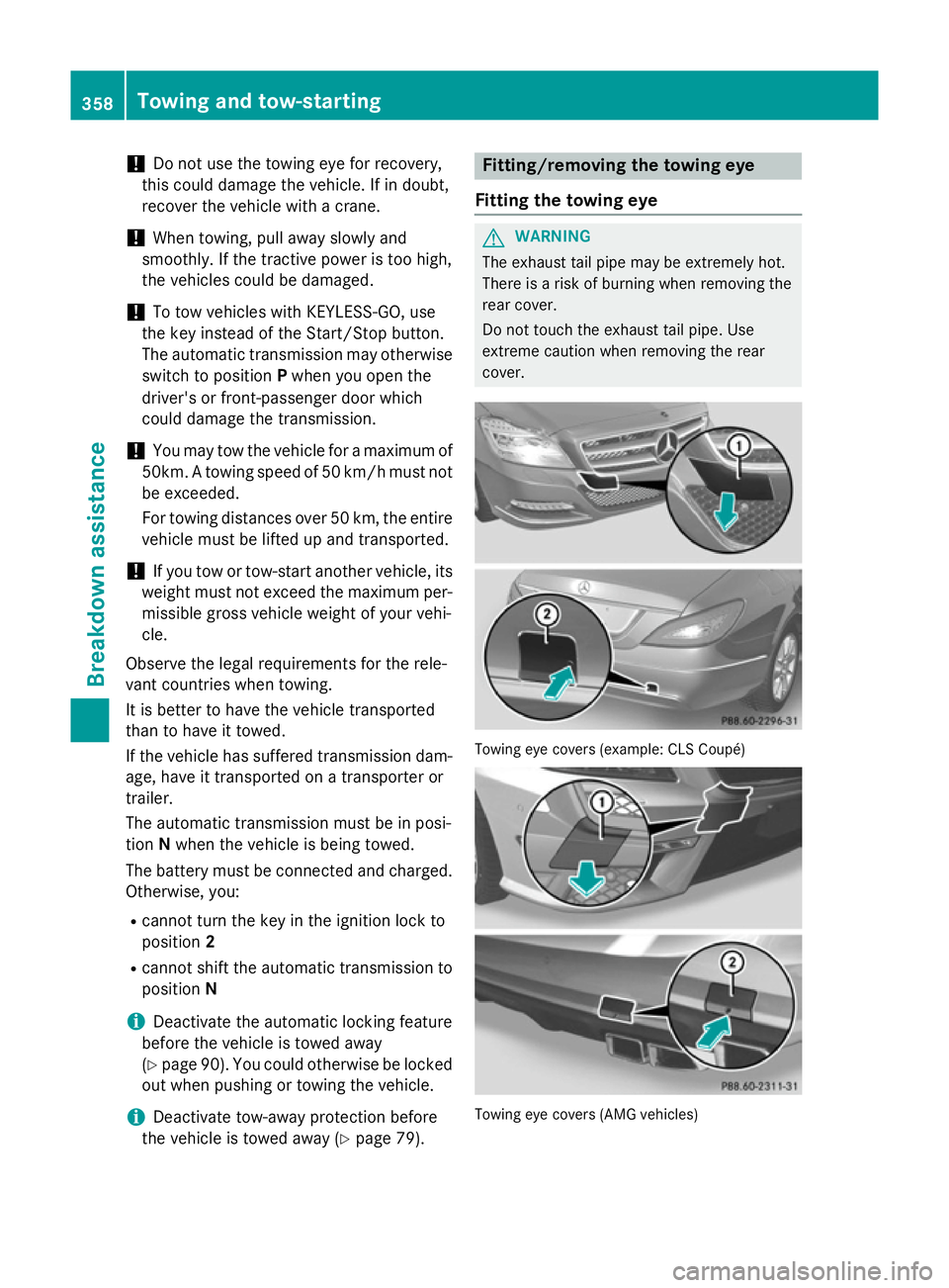
the vehicle is towed away (Y page 79). Fitting/removing the towing eye
Fitting the towing eye G
WARNING
The exhaust tail pipe may be extremely hot.
There is a risk of burning when removing the
rear cover.
Do not touch the exhaust tail pipe. Use
extreme caution when removing the rear
cover. Towing eye covers (example: CLS Coupé)
Towing eye covers (AMG vehicles)358
Towing and tow-startingBreakdown assistance
Page 362 of 417
The mountings for the removable towing eyes
are located in the bumpers. They are at the
front and at the rear under the covers.
X Remove the towing eye from the vehicle
tool kit (Y page 345).
X Pull cover :out of the bumper in the
direction of the arrow by inserting your fin-
gers into the recess.
X Press the mark on cover ;inwards in the
direction of the arrow.
X Remove cover ;from the opening.
X Screw the towing eye in clockwise to the
stop and tighten it.
Removing the towing eye X
Loosen the towing eye and unscrew it.
X Position cover :on top of the bumper and
press it in at the bottom until it engages.
X Attach cover ;to the bumper and press
until it engages.
X Place the towing eye in the vehicle tool kit. Towing the vehicle with the rear axle
raised
! The ignition must be switched off if you
are towing the vehicle with the rear axle
raised. Intervention by ESP ®
could other-
wise damage the brake system.
Only possible on vehicles without
4MATIC.
X Switch on the hazard warning lamps
(Y page 126).
X Turn the key in the ignition lock to position
0 and remove the key from the ignition
lock.
X When leaving the vehicle, take the key or
the KEYLESS-GO key with you.
When towing your vehicle with the rear axle
raised, it is important that you observe the
safety instructions (Y page 357). Towing the vehicle with both axles on
the ground
It is important that you observe the safety
instructions when towing away your vehicle
(Y page 357).
The automatic transmission automatically
shifts to position Pwhen you open the driver's
or front-passenger door or when you remove the key from the ignition lock. In order to
ensure that the automatic transmission stays
in position Nwhen towing the vehicle, you
must observe the following points:
X Make sure that the vehicle is stationary and
that the key is in position 0in the ignition
lock.
X Turn the key to position 2in the ignition
lock.
On vehicles with KEYLESS-GO, use the key instead of the Start/Stop button
(Y page 159).
X Depress and hold the brake pedal.
X Shift the automatic transmission to posi-
tion N.
X Release the brake pedal.
X Release the parking brake.
X Switch on the hazard warning lamps
(Y page 126).
X Leave the key in position 2in the ignition
lock.
i When towing with the hazard warning
lamps switched on, use the combination
switch as usual to signal a change of direc- tion. In this case, only the turn signals for
the desired direction flash. When you reset
the combination switch, the hazard warn-
ing lamps start flashing again. Transporting the vehicle
! You may only secure the vehicle by the
wheels, not by parts of the vehicle such as
axle or steering components. Otherwise,
the vehicle could be damaged. Towing and tow-starting
359Breakdown assistance Z
Page 363 of 417
The towing eye can be used to pull the vehicle
onto a trailer or transporter for transporta-
tion.
The towing eyes or trailer tow hitch can be
used to pull the vehicle onto a trailer or trans-
porter if you wish to transport it.
X Turn the key to position 2in the ignition
lock.
X Shift the automatic transmission to posi-
tion N.
As soon as the vehicle is loaded:
X Prevent the vehicle from rolling away by
applying the parking brake.
X Shift the automatic transmission to posi-
tion P.
X Turn the key in the ignition lock to position
0 and remove the key from the ignition
lock.
X Secure the vehicle. Notes for 4MATIC vehicles
! Vehicles with 4MATIC must not be towed
with the front or rear axle raised; otherwise,
the transmission may be damaged.
If the vehicle has transmission damage or
damage to the front or rear axle, have it trans- ported on a transporter or trailer.
In the event of damage to the electrical
system
If the battery is defective, the automatic
transmission will be locked in position P. To
shift the automatic transmission to position
N, you must provide power to the vehicle's
electrical system in the same way as when
jump-starting (Y page 355).
Have the vehicle transported on a transporter
or trailer. Tow-starting (emergency engine
starting)
! Vehicles with automatic transmission
must not be tow-started. The transmission
may otherwise be damaged.
i You can find information on "Jump-start-
ing" under (Y page 355). Electrical fuses
Important safety notes
G
WARNING
If you manipulate, bridge or replace a faulty
fuse with a fuse of a higher amperage, the
electric cables could be overloaded. This may result in a fire. There is a risk of an accident
and injury.
Always replace faulty fuses with specified new fuses of the correct amperage.
! Only use fuses that have been approved
for Mercedes-Benz vehicles and which
have the correct fuse rating for the system concerned. Otherwise, components or sys-
tems could be damaged.
The fuses in your vehicle serve to disconnect
faulty circuits. If a fuse blows, all the compo- nents on the circuit and their functions will
fail.
Blown fuses must be replaced with fuses of
the same rating, which you can recognise by
the colour and fuse rating. The fuse ratings
are listed in the fuse allocation chart.
If the newly inserted fuse also blows, have the
cause traced and rectified at a qualified spe-
cialist workshop, e.g. a Mercedes-Benz Ser-
vice Centre. Before replacing a fuse
Observe the important safety notes
(Y page 360) 360
Electrical fusesBreakdown assistance
Page 364 of 417

X
Secure the vehicle against rolling away
(Y page 180).
X Switch off all electrical consumers.
X Turn the key to position 0in the ignition
lock and remove it (Y page 159).
or
X On vehicles with KEYLESS-GO, make sure
the ignition is switched off (Y page 159).
All indicator lamps in the instrument cluster
must be off.
The fuses are located in various fuse boxes:
R fuse box in the engine compartment on the
left-hand side of the vehicle, when viewed
in the direction of travel
R CLS Coupé: fuse box located in the boot on
the right-hand side when viewed in the
direction of travel
R CLS Shooting Brake: fuse box located in
the luggage compartment on the right-
hand side when viewed in the direction of
travel
CLS Coupé: the fuse allocation chart is loca-
ted in the vehicle tool kit in the stowage com-
partment under the boot floor (Y page 345).
CLS Shooting Brake: the fuse allocation
chart is located in the vehicle tool kit in the
stowage compartment under the luggage
compartment floor (Y page 345).Fuse box in the engine compartment
Observe the important safety notes
(Y page 360) G
WARNING
When the bonnet is open, and the windscreen wipers are set in motion, you can be injured by
the wiper linkage. There is a risk of injury.
Always switch off the windscreen wipers and
the ignition before opening the bonnet.
! Make sure that no moisture can enter the
fuse box when the cover is open. !
When closing the cover, make sure that it
is lying correctly on the fuse box. Moisture
seeping in or dirt could otherwise impair
the operation of the fuses.
X Make sure that the windscreen wipers are
switched off.
X Open the bonnet. X
Remove any existing moisture from the
fuse box using a dry cloth.
X To open: take lines ;out of the guides.
X Move lines ;to one side. Route the lines
behind connection =to do this.
X Open retaining clamps :.
X Remove the fuse box cover forwards.
X To close: check whether the rubber seal is
seated correctly in the cover.
X Insert the cover at the rear of the fuse box
into the retainer.
X Fold down cover and close clamps :.
X Secure lines ;in the guides.
X Close the bonnet. Fuse box in the boot (CLS Coupé)
Observe the important safety notes
(Y page 360)
! Make sure that no moisture can enter the
fuse box when the cover is open.
! When closing the cover, make sure that it
is lying correctly on the fuse box. Moisture seeping in or dirt could otherwise impair
the operation of the fuses. Electrical fuses
361Breakdown assistance Z
Page 373 of 417
for the respective operating conditions.
The recommended tyre pressures can be
found in the tyre pressure table on the fuel
filler flap.
The tyre pressure loss warning system can only give reliable warnings if you have set
the correct tyre pressure. If an incorrect
tyre pressure is set, these incorrect values
will be monitored.
X Observe the notes in the section on tyre
pressures (Y page 367).
X Make sure that the key is in position 2in the
ignition lock (Y page 159).
X Press the =or; button on the steer-
ing wheel to select the Serv.
Serv. menu.
X Press the 9or: button on the steer-
ing wheel to select the Tyre pressure
Tyre pressure
menu.
X Press the abutton.
The Run Flat Indicator active
Run Flat Indicator active
Restart Restart with
withOK
OKmessage appears in the
multifunction display.
If you wish to confirm the restart: X Press the abutton.
The Tyre press. now OK?
Tyre press. now OK? message
appears in the multifunction display.
X Press the 9or: button to select
Yes
Yes.
X Press the abutton.
The Run Flat Indicator restarted
Run Flat Indicator restarted
message appears in the multifunction dis-
play.
After a teach-in period, the tyre pressure
loss warning system will monitor the set
tyre pressures of all four tyres.
If you wish to cancel the restart:
X Press the %button.
or
X When the Tyre
Tyre press. press. now
nowOK?
OK?message
appears, press the 9or: button to
select Cancel
Cancel .
X Press the abutton.
The tyre pressure values stored at the last
restart will continue to be monitored. Tyre pressure monitor
General notes If a tyre pressure monitor system is fitted, the
vehicle's wheels have sensors fitted that
monitor the tyre pressures in all four tyres.
The tyre pressure monitor warns you if the
pressure drops in one or more of the tyres.
The tyre pressure monitor only functions if
the corresponding sensors are fitted to all
wheels.
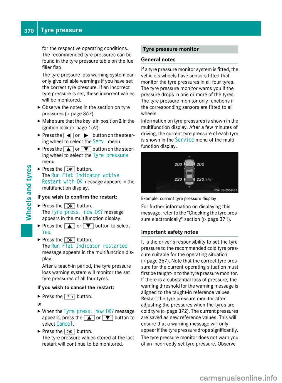
Information on tyre pressures is shown in the multifunction display. After a few minutes of
driving, the current tyre pressure of each tyre
is shown in the Service Servicemenu of the multi-
function display. Example: current tyre pressure display
For further information on displaying this
message, refer to the "Checking the tyre pres-
sure electronically" section (Y page 371).
Important safety notes It is the driver's responsibility to set the tyre
pressure to the recommended cold tyre pres-
sure suitable for the operating situation
(Y page 367). Note that the correct tyre pres-
sure for the current operating situation must
first be taught-in to the tyre pressure monitor. If there is a substantial loss of pressure, the
warning threshold for the warning message isaligned to the taught-in reference values.
Restart the tyre pressure monitor after
adjusting the pressures when the tyres are
cold tyre (Y page 372). The current pressures
are saved as new reference values. This will
ensure that a warning message will only
appear if the tyre pressure drops significantly.
The tyre pressure monitor does not warn you
of an incorrectly set tyre pressure. Observe 370
Tyre pressureWheels and tyres
Page 374 of 417
the notes on the recommended tyre pressure
(Y page 367).
The tyre pressure monitor is not able to warn you of a sudden loss of pressure, e.g. if the
tyre is punctured by a foreign object. In the
event of a sudden loss of pressure, bring the
vehicle to a halt by braking carefully. Avoid
abrupt steering manoeuvres.
The tyre pressure monitor has a yellow warn-
ing lamp in the instrument cluster for indicat-
ing a pressure loss or malfunction. Depending on how the warning lamp flashes or lights up,
a tyre pressure that is too low or a malfunc-
tion in the tyre pressure monitor is indicated:
R if the warning lamp is lit continuously, the
tyre pressure on one or more tyres is sig-
nificantly too low. The tyre pressure moni-
tor is not malfunctioning.
R if the warning lamp flashes for around a
minute and then remains lit constantly, the
tyre pressure monitor is malfunctioning.
i In addition to the warning lamp, a mes-
sage appears in the multifunction display.
Further information can be found at
(Y page 280).
If the tyre pressure monitor is malfunctioning,
it may take more than ten minutes for the tyre pressure warning lamp to inform you of the
malfunction by flashing for approximately one
minute and then remaining lit. When the fault
has been rectified, the tyre pressure warning lamp goes out after you have driven for a few
minutes.
The tyre pressure values indicated by the on- board computer may differ from those meas-
ured at a filling station using a pressure
gauge. The tyre pressures shown by the on-
board computer refer to those measured at
sea level. At high altitudes, the tyre pressure
values indicated by a pressure gauge are
higher than those shown by the on-board
computer. In this case, do not reduce the tyre
pressures.
The operation of the tyre pressure monitor
can be affected by interference from radio transmitting equipment (e.g. radio head-
phones, two-way radios) that may be being
operated in or near the vehicle.
Checking the tyre pressure electroni-
cally X
Make sure that the key is in position 2in the
ignition lock (Y page 159).
X Press the =or; button on the steer-
ing wheel to select the Service
Service menu.
X Press the 9or: button to select
Tyre pressure Tyre pressure.
X Press the abutton.
The current tyre pressure for each wheel
will be displayed in the multifunction dis-
play.
If the vehicle has been parked for over
20 minutes, the Tyre Tyrepressures
pressures will
willbe
be
displayed after a few minutes of
displayed after a few minutes of
driving driving message appears.
After a teach-in period, the tyre pressure
monitor automatically detects new wheels or new sensors. As long as a clear allocation of
the tyre pressure values to the individual
wheels is not possible, the Tyre pressure Tyre pressure
monitor active monitor active display message is shown
instead of the tyre pressure display. The tyre
pressures are already being monitored.
i If an emergency spare wheel is fitted, for
a few minutes the system may continue to
show the tyre pressure of the wheel that
has been removed. If this occurs, note that the value displayed for the position where
the spare wheel is fitted is not the same asthe current tyre pressure of the emergencyspare wheel. Tyre pressure
371Wheels and tyres Z