2014 MERCEDES-BENZ C-CLASS ESTATE key battery
[x] Cancel search: key batteryPage 196 of 489
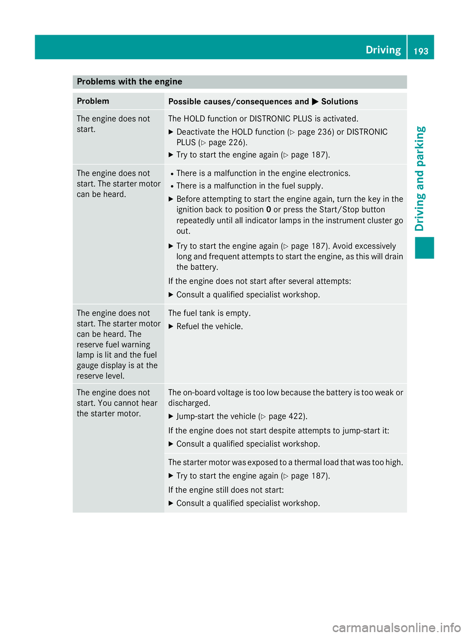
Problems with the engine
Problem
Possible causes/consequences and
M
MSolutions The engine does not
start. The HOLD function or DISTRONIC PLUS is activated.
X Deactivate the HOLD function (Y page 236) or DISTRONIC
PLUS (Y page 226).
X Try to start the engine again (Y page 187).The engine does not
start. The starter motor
can be heard. R
There is a malfunction in the engine electronics.
R There is a malfunction in the fuel supply.
X Before attempting to start the engine again, turn the key in the
ignition back to position 0or press the Start/Stop button
repeatedly until all indicator lamps in the instrument cluster go
out.
X Try to start the engine again (Y page 187). Avoid excessively
long and frequent attempts to start the engine, as this will drain
the battery.
If the engine does not start after several attempts: X Consult a qualified specialist workshop. The engine does not
start. The starter motor
can be heard. The
reserve fuel warning
lamp is lit and the fuel
gauge display is at the
reserve level. The fuel tank is empty.
X Refuel the vehicle. The engine does not
start. You cannot hear
the starter motor. The on-board voltage is too low because the battery is too weak or
discharged.
X Jump-start the vehicle (Y page 422).
If the engine does not start despite attempts to jump-start it:
X Consult a qualified specialist workshop. The starter motor was exposed to a thermal load that was too high.
X Try to start the engine again (Y page 187).
If the engine still does not start: X Consult a qualified specialist workshop. Driving
193Driving and parking Z
Page 211 of 489
Problem
Possible causes/consequences and
M
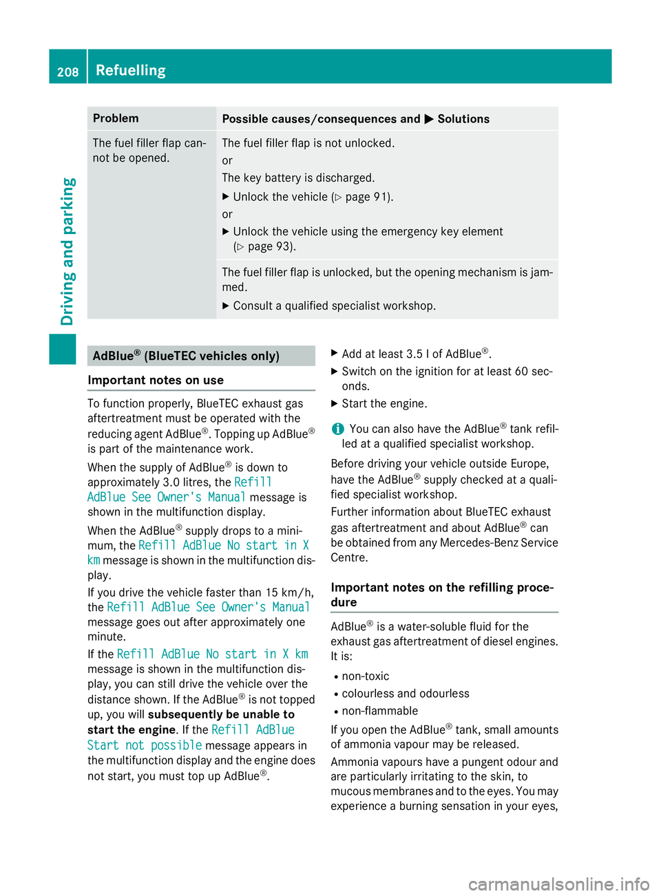
MSolutions The fuel filler flap can-
not be opened. The fuel filler flap is not unlocked.
or
The key battery is discharged.
X Unlock the vehicle (Y page 91).
or
X Unlock the vehicle using the emergency key element
(Y page 93). The fuel filler flap is unlocked, but the opening mechanism is jam-
med.
X Consult a qualified specialist workshop. AdBlue
®
(BlueTEC vehicles only)
Important notes on use To function properly, BlueTEC exhaust gas
aftertreatment must be operated with the
reducing agent AdBlue ®
. Topping up AdBlue ®
is part of the maintenance work.
When the supply of AdBlue ®
is down to
approximately 3.0 litres, the Refill
Refill
AdBlue See Owner's Manual AdBlue See Owner's Manual message is
shown in the multifunction display.
When the AdBlue ®
supply drops to a mini-
mum, the Refill
Refill AdBlue
AdBlueNo
No start
start in
inX
X
km
km message is shown in the multifunction dis-
play.
If you drive the vehicle faster than 15 km/h,
the Refill AdBlue See Owner's Manual Refill AdBlue See Owner's Manual
message goes out after approximately one
minute.
If the Refill AdBlue No start in X km Refill AdBlue No start in X km
message is shown in the multifunction dis-
play, you can still drive the vehicle over the
distance shown. If the AdBlue ®
is not topped
up, you will subsequently be unable to
start the engine. If the Refill AdBlue
Refill AdBlue
Start not possible
Start not possible message appears in
the multifunction display and the engine does
not start, you must top up AdBlue ®
. X
Add at least 3.5 l of AdBlue ®
.
X Switch on the ignition for at least 60 sec-
onds.
X Start the engine.
i You can also have the AdBlue ®
tank refil-
led at a qualified specialist workshop.
Before driving your vehicle outside Europe,
have the AdBlue ®
supply checked at a quali-
fied specialist workshop.
Further information about BlueTEC exhaust
gas aftertreatment and about AdBlue ®
can
be obtained from any Mercedes-Benz Service Centre.
Important notes on the refilling proce-
dure AdBlue
®
is a water-soluble fluid for the
exhaust gas aftertreatment of diesel engines. It is:
R non-toxic
R colourless and odourless
R non-flammable
If you open the AdBlue ®
tank, small amounts
of ammonia vapour may be released.
Ammonia vapours have a pungent odour and
are particularly irritating to the skin, to
mucous membranes and to the eyes. You may experience a burning sensation in your eyes, 208
RefuellingDriving and parking
Page 280 of 489
?
High-voltage battery
A Energy flow
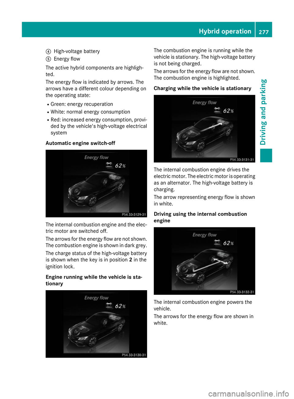
The active hybrid components are highligh-
ted.
The energy flow is indicated by arrows. The
arrows have a different colour depending on
the operating state:
R Green: energy recuperation
R White: normal energy consumption
R Red: increased energy consumption, provi-
ded by the vehicle's high-voltage electrical
system
Automatic engine switch-off The internal combustion engine and the elec-
tric motor are switched off.
The arrows for the energy flow are not shown.
The combustion engine is shown in dark grey.
The charge status of the high-voltage battery is shown when the key is in position 2in the
ignition lock.
Engine running while the vehicle is sta-
tionary The combustion engine is running while the
vehicle is stationary. The high-voltage battery
is not being charged.
The arrows for the energy flow are not shown. The combustion engine is highlighted.
Charging while the vehicle is stationary The internal combustion engine drives the
electric motor. The electric motor is operating
as an alternator. The high-voltage battery is
charging.
The arrow representing energy flow is shown in white.
Driving using the internal combustion
engine The internal combustion engine powers the
vehicle.
The arrows for the energy flow are shown in
white. Hybrid operation
277Driving and parking Z
Page 293 of 489
X
Press the ball coupling in the direction of
the arrow until it engages audibly behind
the bumper.
The indicator lamp on the release knob
goes out and the message in the multifunc-
tion display disappears. Trailer power supply
! You can connect accessories with a
power rating of up to 240 W to the perma-
nent power supply and with a power rating of up to 180 W to the power supply that is
switched on via the ignition lock.
The trailer battery may not be charged from the power supply.
When it leaves the factory, your vehicle's
trailer socket is equipped with a permanent
power supply and a power supply that is
switched on via the ignition lock.
The permanent power supply is supplied via
trailer socket pin 9.
The power supply that is switched on via the
ignition lock is supplied via trailer socket pin
10.
The trailer's permanent power supply is
switched off in the event of low vehicle supply
voltage and after six hours at the latest.
You can find more information about fitting
the trailer electrics at a qualified specialist
workshop.
X To switch the connected power supply
on or off: turn the key in the ignition lock to
position 2or 0respectively (Y page 185). Bulb failure indicator for LED lamps
If LED lamps are fitted in the trailer, an error
message may appear in the multifunction dis-
play even if there is no fault. The reason for
the error message may be that the current
has fallen below the minimum of 50 mA.
To ensure reliable operation of the bulb failure indicator, each LED chain in the trailer lighting
must be guaranteed a minimum current of
50 mA. Trailer with 7-pin connector
General notes Trailer with 7-pin connector:
you can con-
nect to the 13-pin socket on the ball coupling
using an adapter or, if necessary, an adapter
cable. Both can be obtained at a qualified
specialist workshop.
Fitting the adapter !
Make sure that there is sufficient cable
play so that the cable cannot become
detached when cornering.
! Remove the installed adapter cable
before folding in the ball coupling. Other-
wise, damage may occur to the rear
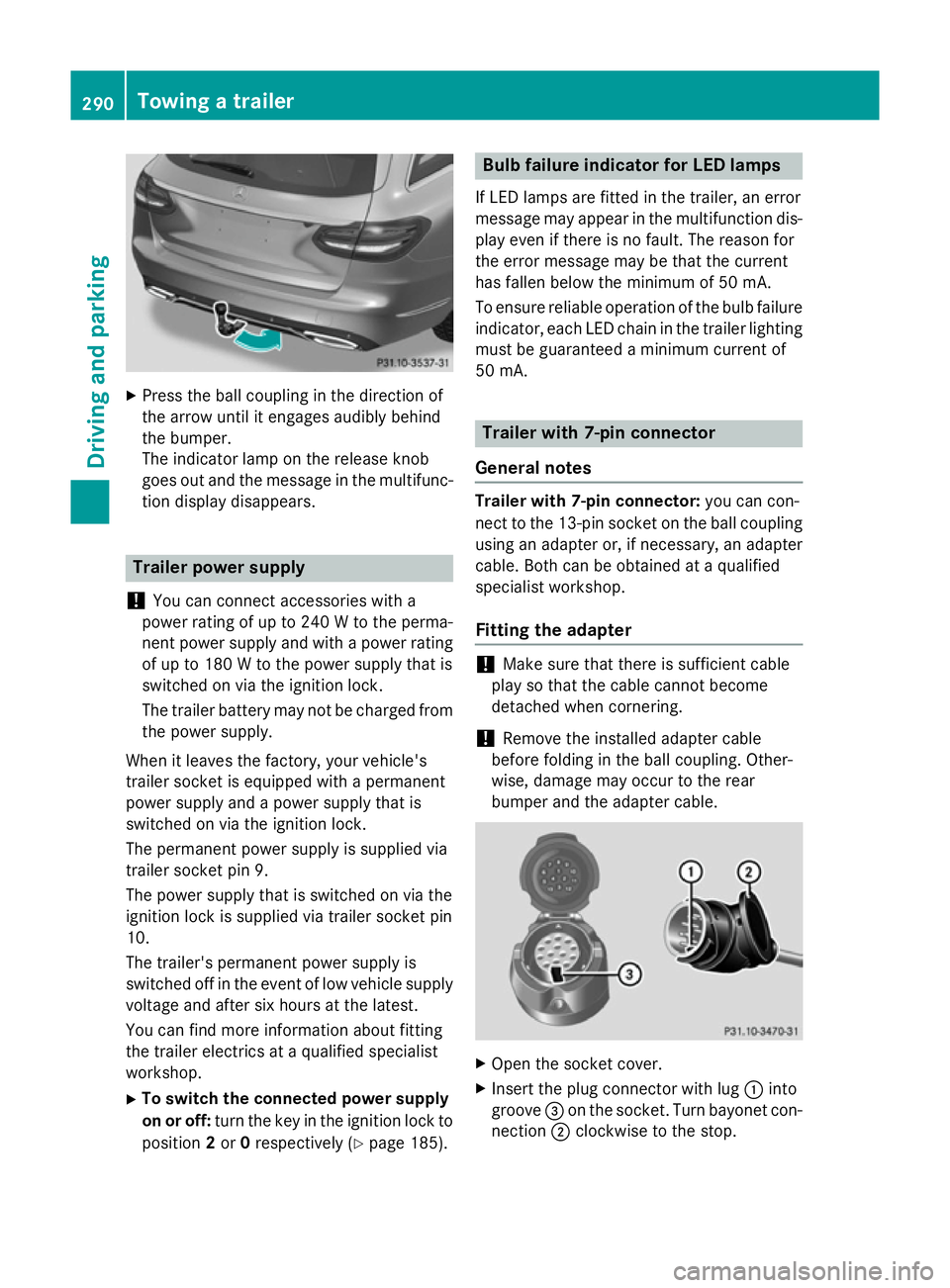
bumper and the adapter cable. X
Open the socket cover.
X Insert the plug connector with lug :into
groove =on the socket. Turn bayonet con-
nection ;clockwise to the stop. 290
Towing a trailerDriving and parking
Page 353 of 489
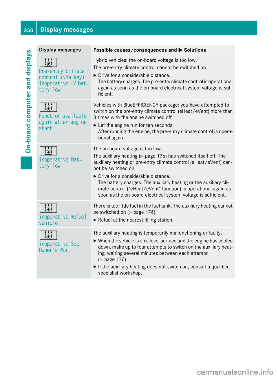
Display messages
Possible causes/consequences and
M
MSolutions &
Pre-entry climate Pre-entry climate
control (via key) control (via key)
inoperative inoperative
HV
HVbat‐
bat‐
tery low
tery low Hybrid vehicles: the on-board voltage is too low.
The pre-entry climate control cannot be switched on.
X Drive for a considerable distance.
The battery charges. The pre-entry climate control is operational
again as soon as the on-board electrical system voltage is suf-
ficient. &
Function Function
available
available
again
again after
afterengine
engine
start
start Vehicles with BlueEFFICIENCY package: you have attempted to
switch on the pre-entry climate control (eHeat/eVent) more than
3 times with the engine switched off.
X Let the engine run for ten seconds.
After running the engine, the pre-entry climate control is opera- tional again. &
inoperative Bat‐ inoperative Bat‐
tery low tery low The on-board voltage is too low.
The auxiliary heating (Y
page 176) has switched itself off. The
auxiliary heating or pre-entry climate control (eHeat/eVent) can-
not be switched on.
X Drive for a considerable distance.
The battery charges. The auxiliary heating or the auxiliary cli-
mate control ("eHeat/eVent" function) is operational again as
soon as the on-board electrical system voltage is sufficient. &
inoperative inoperative
Refuel
Refuel
vehicle
vehicle There is too little fuel in the fuel tank. The auxiliary heating cannot
be switched on (Y page 176).
X Refuel at the nearest filling station. &
inoperative See inoperative See
Owner's Man. Owner's Man. The auxiliary heating is temporarily malfunctioning or faulty.
X When the vehicle is on a level surface and the engine has cooled
down, make up to four attempts to switch on the auxiliary heat- ing, waiting several minutes between each attempt
(Y page 176).
X If the auxiliary heating does not switch on, consult a qualified
specialist workshop. 350
Display
messagesOn-board computer and displays
Page 355 of 489
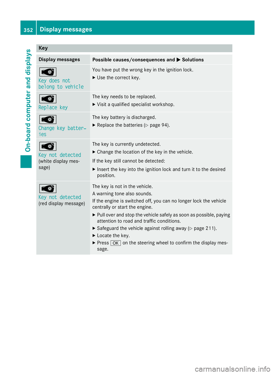
Key
Display messages
Possible causes/consequences and
M
MSolutions Â
Key does not Key does not
belong to vehicle belong to vehicle You have put the wrong key in the ignition lock.
X Use the correct key. Â
Replace key Replace key The key needs to be replaced.
X Visit a qualified specialist workshop. Â
Change key batter‐ Change key batter‐
ies ies The key battery is discharged.
X Replace the batteries (Y page 94).Â
Key not detected Key not detected
(white display mes-
sage) The key is currently undetected.
X Change the location of the key in the vehicle.
If the key still cannot be detected: X Insert the key into the ignition lock and turn it to the desired
position. Â
Key not detected Key not detected
(red display message) The key is not in the vehicle.
A warning tone also sounds.
If the engine is switched off, you can no longer lock the vehicle
centrally or start the engine.
X Pull over and stop the vehicle safely as soon as possible, paying
attention to road and traffic conditions.
X Safeguard the vehicle against rolling away (Y page 211).
X Locate the key.
X Press aon the steering wheel to confirm the display mes-
sage. 352
Display
messagesOn-board computer and displays
Page 388 of 489
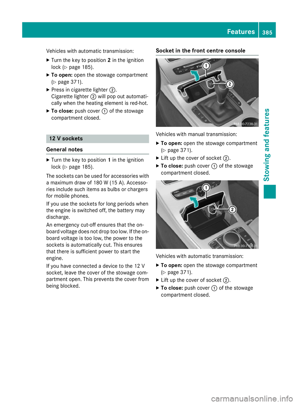
Vehicles with automatic transmission:
X
Turn the key to position 2in the ignition
lock (Y page 185).
X To open: open the stowage compartment
(Y page 371).
X Press in cigarette lighter ;.
Cigarette lighter ;will pop out automati-
cally when the heating element is red-hot.
X To close: push cover :of the stowage
compartment closed. 12 V sockets
General notes X
Turn the key to position 1in the ignition
lock (Y page 185).
The sockets can be used for accessories with a maximum draw of 180 W(15 A). Accesso-
ries include such items as bulbs or chargers
for mobile phones.
If you use the sockets for long periods when
the engine is switched off, the battery may
discharge.
An emergency cut-off ensures that the on-
board voltage does not drop too low. If the on-
board voltage is too low, the power to the
sockets is automatically cut. This ensures
that there is sufficient power to start the
engine.
If you have connected a device to the 12 V
socket, leave the cover of the stowage com-
partment open. This prevents the cover from
being blocked. Socket in the front cent
re console Vehicles with manual transmission:
X
To open: open the stowage compartment
(Y page 371).
X Lift up the cover of socket ;.
X To close: push cover :of the stowage
compartment closed. Vehicles with automatic transmission:
X
To open: open the stowage compartment
(Y page 371).
X Lift up the cover of socket ;.
X To close: push cover :of the stowage
compartment closed. Features
385Stowing an d features Z
Page 405 of 489
blades. This will prevent smears and reduce
wiping noises caused by residue on the wind-
screen.
Washing by hand In some countries, washing by hand is only
allowed at specially equipped washing bays.
Observe the legal requirements for each indi-
vidual country.
X Do not use hot water and do not wash the
vehicle in direct sunlight.
X Use a soft sponge to clean.
X Use a mild cleaning agent, such as a car
shampoo approved by Mercedes-Benz.
X Thoroughly hose down the vehicle with a
gentle jet of water.
X Do not point the water jet directly towards
the air inlet.
X Use plenty of water and rinse out the
sponge frequently.
X Rinse the vehicle with clean water and dry
thoroughly with a chamois.
X Do not let the cleaning agent dry on the
paintwork.
When using the vehicle in winter, remove all
traces of road salt deposits carefully and as
soon as possible.
High-pressure cleaning equipment G
WARNING
The water jet of circular-jet nozzles (dirt grind- ers) can cause damage not visible from the
outside to tyres or chassis components. Com-
ponents damaged in this way can unexpect-
edly fail. There is a risk of an accident.
Do not use high-pressure cleaners with circu-
lar-jet nozzles to clean the vehicle. Have dam- aged tyres or chassis components replaced
immediately.
! Always maintain a distance of at least
30 cm between the vehicle and the high-
pressure cleaner nozzle. Information about the correct distance is available from the
equipment manufacturer.
Move the high-pressure cleaner nozzle
around when cleaning your vehicle.
Do not aim directly at any of the following:
R tyres
R door gaps, roof gaps, joints etc.
R electrical components
R battery
R connectors
R lights
R seals
R trim elements
R ventilation slots
Damaged seals or electrical components
can lead to leaks or failures.
! If the key is within the rear detection
range of KEYLESS-GO, the following situa-
tions, for example, could lead to the boot lid opening unintentionally:
R using a car wash
R using a high-pressure cleaner
Make sure that the key is at least 3 m away
from the vehicle.
Cleaning the paintwork !
Do not affix:
R stickers
R films
R magnetic plates or similar items
to painted surfaces. You could otherwise
damage the paintwork.
Scratches, corrosive deposits, areas affected by corrosion and damage caused by inade-
quate care cannot always be completely
repaired. In such cases, visit a qualified spe-
cialist workshop.
X Remove impurities immediately, where
possible, whilst avoiding rubbing too hard.
X Soak insect remains with insect remover
and rinse off the treated areas afterwards. 402
CareMaintenance and care