2014 MERCEDES-BENZ C-CLASS ESTATE lock
[x] Cancel search: lockPage 445 of 489
Vehicles with an emergency spare wheel:
in the event of a flat tyre, the emergency
spare wheel is fitted according to the descrip-
tion under "Fitting a wheel" (Y page 442).Interchanging the wheels
G
WARNING
Interchanging the front and rear wheels may
severely impair the driving characteristics if
the wheels or tyres have different dimensions. The wheel brakes or suspension components may also be damaged. There is a risk of acci-
dent.
Interchange front and rear wheels only if the
wheels and tyres are of the same dimensions.
! On vehicles fitted with a tyre pressure
monitor, electronic components are loca-
ted in the wheel.
Tyre-fitting tools should not be applied in
the area of the valve, as this could damage
the electronic components.
Only have tyres changed at a qualified spe- cialist workshop.
Interchanging the front and rear wheels of
differing dimensions can render the general
operating permit invalid.
Observe the instructions and safety notes in
the "Fitting a wheel" section (Y page 442).
The wear patterns on the front and rear tyres differ depending on the operating conditions.Interchange the wheels before a clear wear
pattern has formed on the tyres. Front tyres
typically wear more on the shoulders and the
rear tyres in the centre.
On vehicles that have the same size front and
rear wheels, you can interchange the wheels
every 5,000 to 10,000 km depending on the
degree of tyre wear. Ensure the direction of
rotation is maintained.
Clean the contact surfaces of the wheel and
the brake disc thoroughly every time a wheel is interchanged. Check the tyre pressure and,
if necessary, restart the tyre pressure loss warning system (Y
page 441)or the tyre pres-
sure monitor (Y page 439). Direction of rotation
Tyres with a specified direction of rotation
have additional benefits, e.g. if there is a risk of aquaplaning. You will only gain these ben-
efits if the correct direction of rotation is
observed.
An arrow on the sidewall of the tyre indicates
its correct direction of rotation. Storing wheels
Store wheels in a cool, dry and preferably
dark place if they are not being used. Protect
the tyres against oil, grease, petrol and diesel. Fitting a wheel
Preparing the vehicle X
Stop the vehicle on solid, non-slippery and
level ground.
X Apply the electric parking brake manually.
X Move the front wheels to the straight-
ahead position.
X Vehicles with manual transmission:
depress the clutch pedal fully and engage
first or reverse gear.
X Vehicles with automatic transmission:
shift the transmission to position P.
X Make sure that in vehicles with AIRMATIC,
the vehicle level is set to "Normal"
(Y page 238).
X Switch off the engine.
X Vehicles without KEYLESS-GO: remove
the key from the ignition lock.
X Vehicles with KEYLESS-GO start-func-
tion or KEYLESS-GO: open the driver's
door.
The on-board electronics now have status
0. This is the same as the key having been removed. 442
Changing a wheelWheels and tyres
Page 446 of 489
X
Vehicles with KEYLESS-GO start-func-
tion or KEYLESS-GO: remove the Start/
Stop button from the ignition lock
(Y page 185).
X If included in the vehicle equipment,
remove the tyre-change tool kit from the
vehicle.
X Secure the vehicle to prevent it from rolling
away.
i Apart from some country-specific var-
iants, vehicles are not equipped with tyre-
changing tools. Some tools for changing a
wheel are specific to the vehicle. For more information on which tools are required to
perform a wheel change on your vehicle,
consult a qualified specialist workshop.
Necessary wheel-changing tools may
include, for example:
R jack
R wheel chock
R wheel wrench
R centring pin
Safeguarding the vehicle against rolling
away If your vehicle is equipped with a wheel chock,
it can be found in the tyre-change tool kit
(Y page 411).
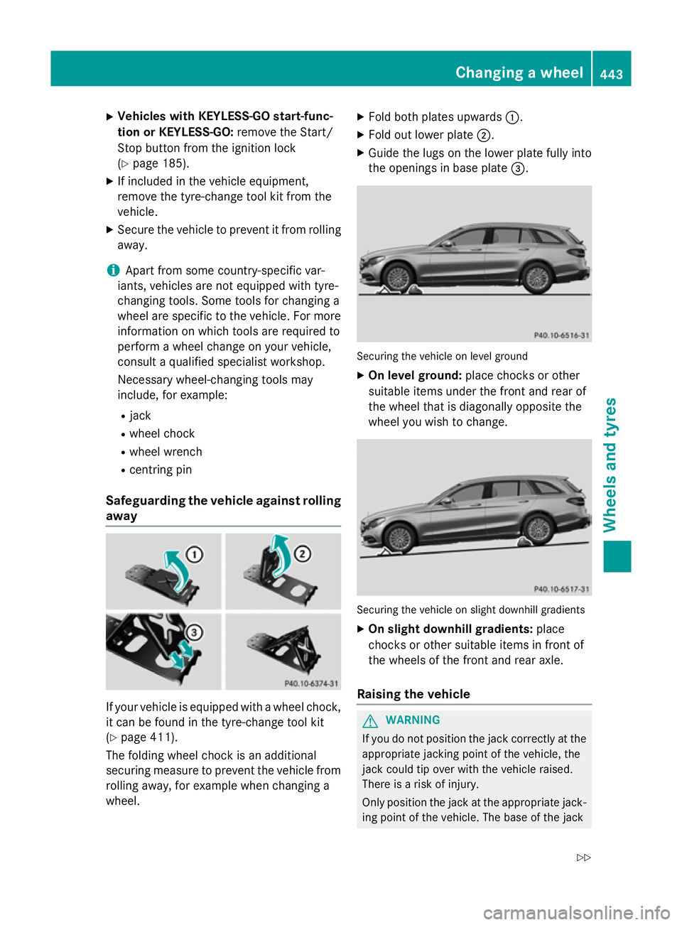
The folding wheel chock is an additional
securing measure to prevent the vehicle from
rolling away, for example when changing a
wheel. X
Fold both plates upwards :.
X Fold out lower plate ;.
X Guide the lugs on the lower plate fully into
the openings in base plate =. Securing the vehicle on level ground
X On level ground: place chocks or other
suitable items under the front and rear of
the wheel that is diagonally opposite the
wheel you wish to change. Securing the vehicle on slight downhill gradients
X On slight downhill gradients: place
chocks or other suitable items in front of
the wheels of the front and rear axle.
Raising the vehicle G
WARNING
If you do not position the jack correctly at the appropriate jacking point of the vehicle, the
jack could tip over with the vehicle raised.
There is a risk of injury.
Only position the jack at the appropriate jack-
ing point of the vehicle. The base of the jack Changing a wheel
443Wheels and tyres
Z
Page 447 of 489
must be positioned vertically, directly under
the jacking point of the vehicle.
Observe the following when raising the
vehicle: R to raise the vehicle, only use the vehicle-
specific jack that has been tested and
approved by Mercedes-Benz. If the jack is
used incorrectly, it could tip over while the vehicle is raised.
R the jack is designed only to raise and hold
the vehicle for a short time while a wheel
is being changed. It is not suitable for per-
forming maintenance work under the vehi- cle.
R avoid changing the wheel on uphill and
downhill slopes.
R before raising the vehicle, secure it from
rolling away by applying the parking brake
and positioning wheel chocks. Do not
release the parking brake while the vehicle
is raised.
R the jack must be placed on a firm, flat and
non-slip surface. On a loose surface, a
large, flat load-bearing underlay must be
used. On a slippery surface, a non-slip
underlay must be used, e.g. rubber mats.
R do not use wooden blocks or similar
objects as a jack underlay. Otherwise, the
jack will not be able to achieve its load-
bearing capacity due to the restricted
height.
R make sure that the distance between the
underside of the tyres and the ground does not exceed 3 cm.
R never place your hands or feet under the
raised vehicle.
R do not lie under the vehicle.
R do not start the engine when the vehicle is
raised.
R do not open or close a door or the tailgate
while the vehicle is raised.
R make sure that no persons are present in
the vehicle when the vehicle is raised. Vehicles with steel wheels and wheel
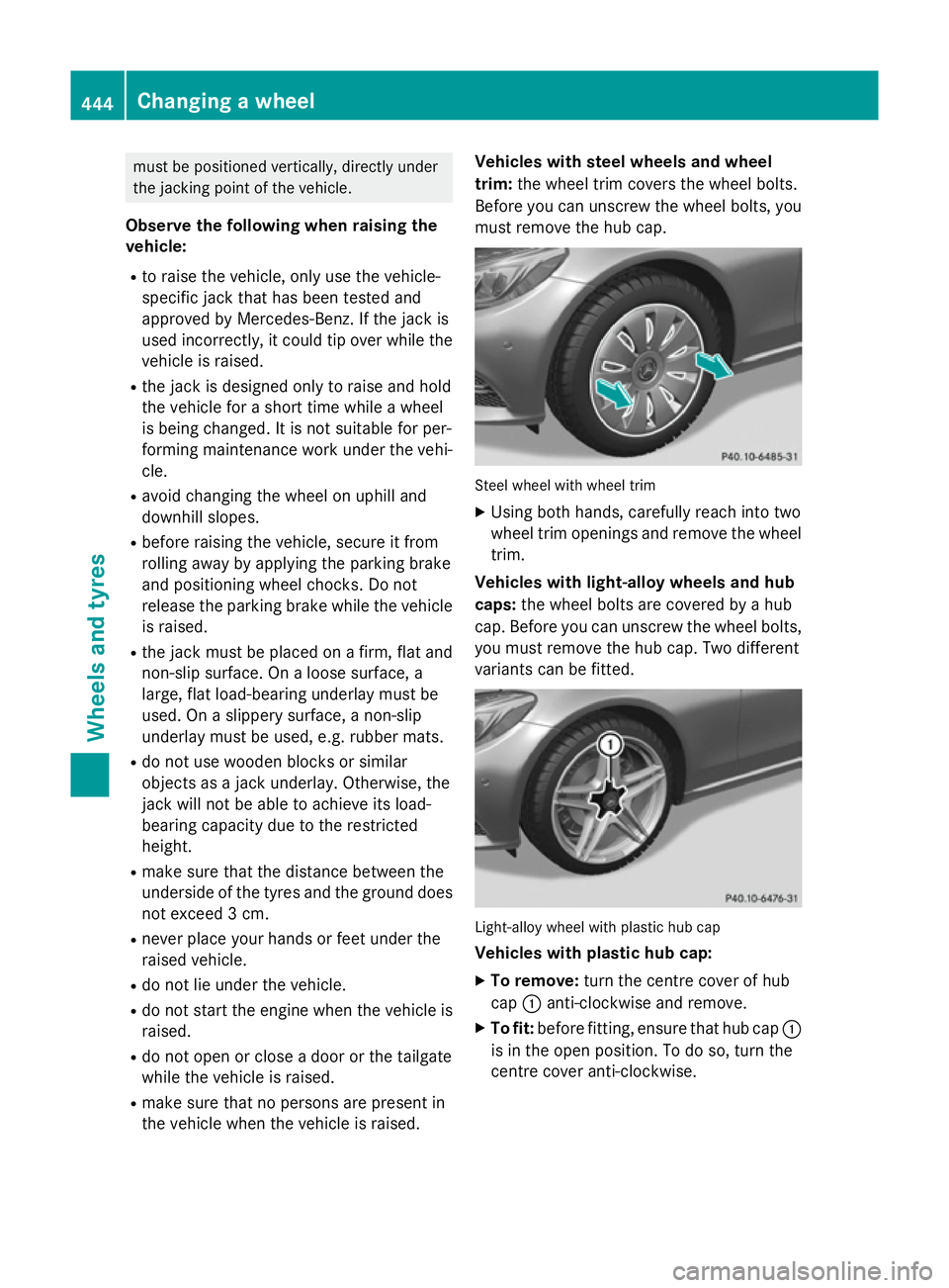
trim:
the wheel trim covers the wheel bolts.
Before you can unscrew the wheel bolts, you must remove the hub cap. Steel wheel with wheel trim
X
Using both hands, carefully reach into two
wheel trim openings and remove the wheel trim.
Vehicles with light-alloy wheels and hub
caps: the wheel bolts are covered by a hub
cap. Before you can unscrew the wheel bolts, you must remove the hub cap. Two different
variants can be fitted. Light-alloy wheel with plastic hub cap
Vehicles with plastic hub cap:
X To remove: turn the centre cover of hub
cap :anti-clockwise and remove.
X To fit: before fitting, ensure that hub cap :
is in the open position. To do so, turn the
centre cover anti-clockwise. 444
Changing a wheelWheels and tyres
Page 448 of 489
X
Put hub cap :in position and turn the
centre cover clockwise until you feel and
hear hub cap :engage.
X Make sure that hub cap :is fitted
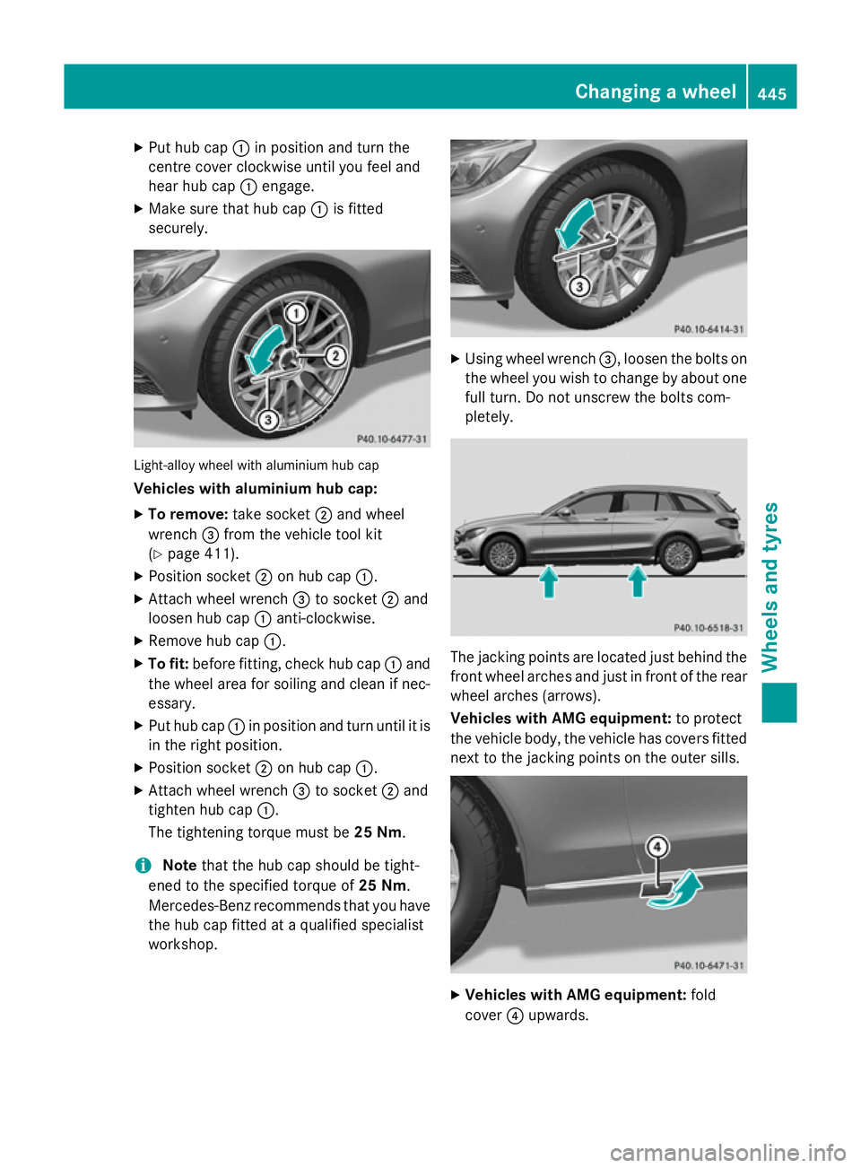
securely. Light-alloy wheel with aluminium hub cap
Vehicles with aluminium hub cap:
X To remove: take socket;and wheel
wrench =from the vehicle tool kit
(Y page 411).
X Position socket ;on hub cap :.
X Attach wheel wrench =to socket ;and
loosen hub cap :anti-clockwise.
X Remove hub cap :.
X To fit: before fitting, check hub cap :and
the wheel area for soiling and clean if nec-
essary.
X Put hub cap :in position and turn until it is
in the right position.
X Position socket ;on hub cap :.
X Attach wheel wrench =to socket ;and
tighten hub cap :.
The tightening torque must be 25 Nm.
i Note
that the hub cap should be tight-
ened to the specified torque of 25 Nm.
Mercedes-Benz recommends that you have the hub cap fitted at a qualified specialist
workshop. X
Using wheel wrench =, loosen the bolts on
the wheel you wish to change by about one full turn. Do not unscrew the bolts com-
pletely. The jacking points are located just behind the
front wheel arches and just in front of the rear wheel arches (arrows).
Vehicles with AMG equipment: to protect
the vehicle body, the vehicle has covers fitted next to the jacking points on the outer sills. X
Vehicles with AMG equipment: fold
cover ?upwards. Changing a wheel
445Wheels and tyres Z
Page 449 of 489
X
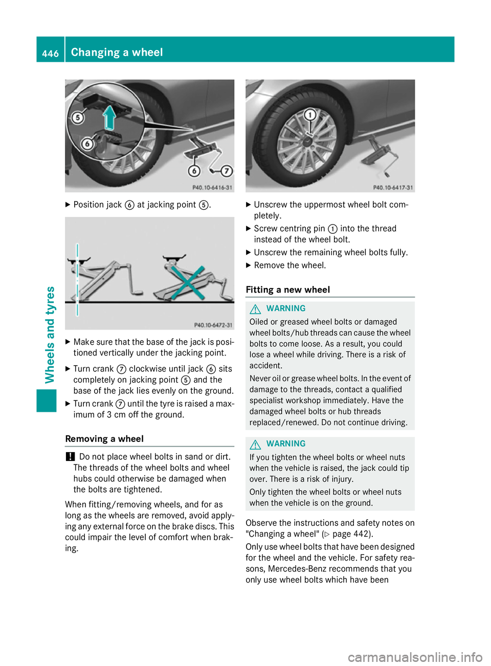
Position jack Bat jacking point A. X
Make sure that the base of the jack is posi-
tioned vertically under the jacking point.
X Turn crank Cclockwise until jack Bsits
completely on jacking point Aand the
base of the jack lies evenly on the ground.
X Turn crank Cuntil the tyre is raised a max-
imum of 3 cm off the ground.
Removing a wheel !
Do not place wheel bolts in sand or dirt.
The threads of the wheel bolts and wheel
hubs could otherwise be damaged when
the bolts are tightened.
When fitting/removing wheels, and for as
long as the wheels are removed, avoid apply- ing any external force on the brake discs. This
could impair the level of comfort when brak-
ing. X
Unscrew the uppermost wheel bolt com-
pletely.
X Screw centring pin :into the thread
instead of the wheel bolt.
X Unscrew the remaining wheel bolts fully.
X Remove the wheel.
Fitting a new wheel G
WARNING
Oiled or greased wheel bolts or damaged
wheel bolts/hub threads can cause the wheel bolts to come loose. As a result, you could
lose a wheel while driving. There is a risk of
accident.
Never oil or grease wheel bolts. In the event ofdamage to the threads, contact a qualified
specialist workshop immediately. Have the
damaged wheel bolts or hub threads
replaced/renewed. Do not continue driving. G
WARNING
If you tighten the wheel bolts or wheel nuts
when the vehicle is raised, the jack could tip
over. There is a risk of injury.
Only tighten the wheel bolts or wheel nuts
when the vehicle is on the ground.
Observe the instructions and safety notes on "Changing a wheel" (Y page 442).
Only use wheel bolts that have been designed
for the wheel and the vehicle. For safety rea-
sons, Mercedes-Benz recommends that you
only use wheel bolts which have been 446
Changing a wheelWheels and tyres
Page 450 of 489
approved for Mercedes-Benz vehicles and the
respective wheel. X
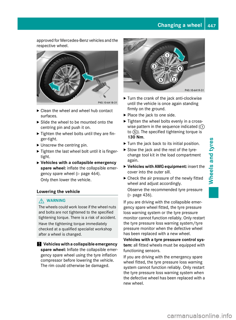
Clean the wheel and wheel hub contact
surfaces.
X Slide the wheel to be mounted onto the
centring pin and push it on.
X Tighten the wheel bolts until they are fin-
ger-tight.
X Unscrew the centring pin.
X Tighten the last wheel bolt until it is finger-
tight.
X Vehicles with a collapsible emergency
spare wheel: inflate the collapsible emer-
gency spare wheel (Y page 464).
Only then lower the vehicle.
Lowering the vehicle G
WARNING
The wheels could work loose if the wheel nuts and bolts are not tightened to the specified
tightening torque. There is a risk of accident.
Have the tightening torque immediately
checked at a qualified specialist workshop
after a wheel is changed.
! Vehicles with a collapsible emergency
spare wheel: Inflate the collapsible emer-
gency spare wheel using the tyre inflation
compressor before lowering the vehicle.
The rim could otherwise be damaged. X
Turn the crank of the jack anti-clockwise
until the vehicle is once again standing
firmly on the ground.
X Place the jack to one side.
X Tighten the wheel bolts evenly in a cross-
wise pattern in the sequence indicated ( :
to A). The specified tightening torque is
130 Nm.
X Turn the jack back to its initial position.
X Stow the jack and the rest of the tyre-
change tool kit in the load compartment
again.
X Vehicles with AMG equipment: insert the
cover into the outer sill.
X Check the air pressure of the newly fitted
wheel and adjust accordingly.
Observe the recommended tyre pressure
(Y page 436).
If you are driving with the collapsible emer-
gency spare wheel fitted, the tyre pressure
loss warning system or the tyre pressure
monitor cannot function reliably. Only restart
the tyre pressure loss warning system/tyre
pressure monitor when the defective wheel
has been replaced with a new wheel.
Vehicles with a tyre pressure control sys-
tem: all fitted wheels must be equipped with
functioning sensors.
If you are driving with the emergency spare
wheel fitted, the tyre pressure loss warning
system cannot function reliably. Only restart
the tyre pressure loss warning system when
the defective wheel has been replaced with a
new wheel. Changing a wheel
447Wheels and tyres Z
Page 467 of 489
Inflating the collapsible emergency
spare wheel
! Inflate the collapsible emergency spare
wheel using the tyre inflation compressor
before lowering the vehicle. The wheel rim
could otherwise be damaged.
! Do not operate the tyre inflation com-
pressor for longer than eight minutes at a
time without a break. It may otherwise
overheat.
The tyre inflation compressor can be oper-
ated again once it has cooled down. X
Mount the collapsible emergency spare
wheel as described (Y page 441).
The collapsible emergency spare wheel
must be mounted before it is inflated.
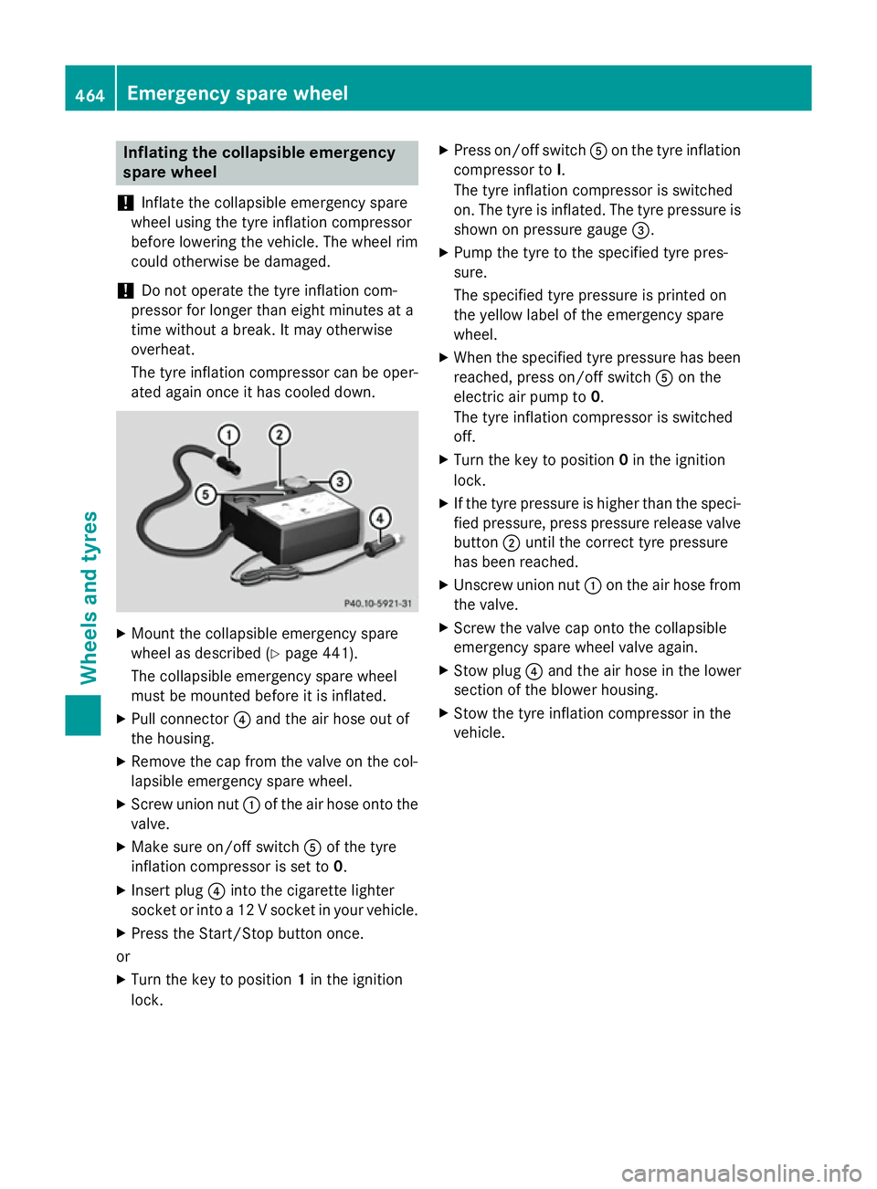
X Pull connector ?and the air hose out of
the housing.
X Remove the cap from the valve on the col-
lapsible emergency spare wheel.
X Screw union nut :of the air hose onto the
valve.
X Make sure on/off switch Aof the tyre
inflation compressor is set to 0.
X Insert plug ?into the cigarette lighter
socket or into a 12 V socket in your vehicle.
X Press the Start/Stop button once.
or X Turn the key to position 1in the ignition
lock. X
Press on/off switch Aon the tyre inflation
compressor to I.
The tyre inflation compressor is switched
on. The tyre is inflated. The tyre pressure is shown on pressure gauge =.
X Pump the tyre to the specified tyre pres-
sure.
The specified tyre pressure is printed on
the yellow label of the emergency spare
wheel.
X When the specified tyre pressure has been
reached, press on/off switch Aon the
electric air pump to 0.
The tyre inflation compressor is switched
off.
X Turn the key to position 0in the ignition
lock.
X If the tyre pressure is higher than the speci-
fied pressure, press pressure release valve
button ;until the correct tyre pressure
has been reached.
X Unscrew union nut :on the air hose from
the valve.
X Screw the valve cap onto the collapsible
emergency spare wheel valve again.
X Stow plug ?and the air hose in the lower
section of the blower housing.
X Stow the tyre inflation compressor in the
vehicle. 464
Emergency spare wheelWheels and ty
res
Page 480 of 489
Further information on coolants can be
found in the Mercedes-Benz Specifications for Service Products, MB Specifications for Service Products 310.1, e.g. on the Inter-
net at http://bevo.mercedes-benz.com.
Or contact a qualified specialist workshop.
! Always use a suitable coolant mixture,
even in countries where high temperatures prevail.
Otherwise, the engine cooling system is not
sufficiently protected from corrosion and
overheating.
i Have the coolant regularly replaced at a
qualified specialist workshop and the
replacement confirmed in the Service
Booklet.
The coolant is a mixture of water and anti-
freeze/corrosion inhibitor. It is responsible
for the following:
R anti-corrosion protection
R antifreeze protection
R raising the boiling point
If antifreeze/corrosion inhibitor is present in
the correct concentration, the boiling point of
the coolant during operation will be approx-
imately 130 †.
The antifreeze/corrosion inhibitor concentra- tion in the engine cooling system should:
R be at least 50%. This will protect the engine
cooling system against freezing down to
approximately -37 †.
R not exceed 55% (antifreeze protection
down to -45 †). Heat will otherwise not be
dissipated as effectively.
Mercedes-Benz recommends an antifreeze/
corrosion inhibitor concentrate in accord-
ance with
MB Specifications for Service Products 310.1
.
The coolant is checked at every maintenance interval at a qualified specialist workshop.
i When the vehicle is first delivered, it is fil-
led with a coolant mixture that ensures adequate antifreeze and corrosion protec-
tion.
i The coolant is checked at every mainte-
nance interval at a qualified specialist
workshop. Windscreen and headlamp cleaning
system
Important safety notes G
WARNING
If windscreen washer concentrate comes into contact with hot components of the engine or
the exhaust system, it can ignite. There is a
risk of fire and injury.
Make sure the windscreen washer concen-
trate does not come into contact with the filler neck.
! Only use washer fluid that is suitable for
plastic lamp lenses, e.g. MB SummerFit or
MB WinterFit. Unsuitable washer fluid
could damage the plastic lenses of the
headlamps.
! Do not use distilled or de-ionised water in
the washer fluid reservoir. Otherwise, the
level sensor may be damaged.
! Only the washer fluids SummerFit and
WinterFit can be mixed. Otherwise, the
spraying nozzles could become blocked.
At temperatures above freezing: X Fill the washer fluid reservoir with a mixture
of water and washer fluid, e.g. MB Sum-
merFit.
Mix 1 part MB SummerFit to 100 parts water.
At temperatures below freezing:
X Fill the washer fluid reservoir with a mixture
of water and washer fluid, e.g. MB Winter-
Fit.
For the correct mixing ratio refer to the
information on the antifreeze reservoir. Service products and capacities
477Technical data Z