2014 MERCEDES-BENZ C-CLASS ESTATE warning light
[x] Cancel search: warning lightPage 274 of 489
G
WARNING
A lane-correcting brake application cannot
always bring the vehicle back into the original lane. There is a risk of an accident.
Always steer, brake or accelerate yourself,
especially if Active Lane Keeping Assist warns
you or makes a lane-correcting brake appli-
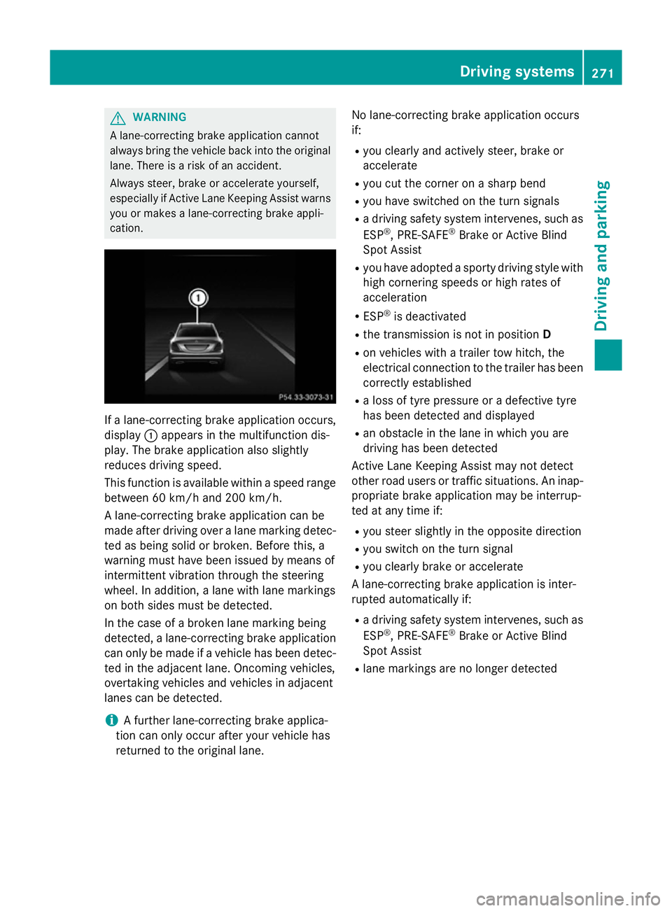
cation. If a lane-correcting brake application occurs,
display :appears in the multifunction dis-
play. The brake application also slightly
reduces driving speed.
This function is available within a speed range
between 60 km/h and 200 km/h.
A lane-correcting brake application can be
made after driving over a lane marking detec- ted as being solid or broken. Before this, a
warning must have been issued by means of
intermittent vibration through the steering
wheel. In addition, a lane with lane markings
on both sides must be detected.
In the case of a broken lane marking being
detected, a lane-correcting brake application can only be made if a vehicle has been detec-
ted in the adjacent lane. Oncoming vehicles,
overtaking vehicles and vehicles in adjacent
lanes can be detected.
i A further lane-correcting brake applica-
tion can only occur after your vehicle has
returned to the original lane. No lane-correcting brake application occurs
if:
R you clearly and actively steer, brake or
accelerate
R you cut the corner on a sharp bend
R you have switched on the turn signals
R a driving safety system intervenes, such as
ESP ®
, PRE-SAFE ®
Brake or Active Blind
Spot Assist
R you have adopted a sporty driving style with
high cornering speeds or high rates of
acceleration
R ESP ®
is deactivated
R the transmission is not in position D
R on vehicles with a trailer tow hitch, the
electrical connection to the trailer has been
correctly established
R a loss of tyre pressure or a defective tyre
has been detected and displayed
R an obstacle in the lane in which you are
driving has been detected
Active Lane Keeping Assist may not detect
other road users or traffic situations. An inap- propriate brake application may be interrup-
ted at any time if:
R you steer slightly in the opposite direction
R you switch on the turn signal
R you clearly brake or accelerate
A lane-correcting brake application is inter-
rupted automatically if:
R a driving safety system intervenes, such as
ESP ®
, PRE-SAFE ®
Brake or Active Blind
Spot Assist
R lane markings are no longer detected Driving systems
271Driving and parking Z
Page 275 of 489
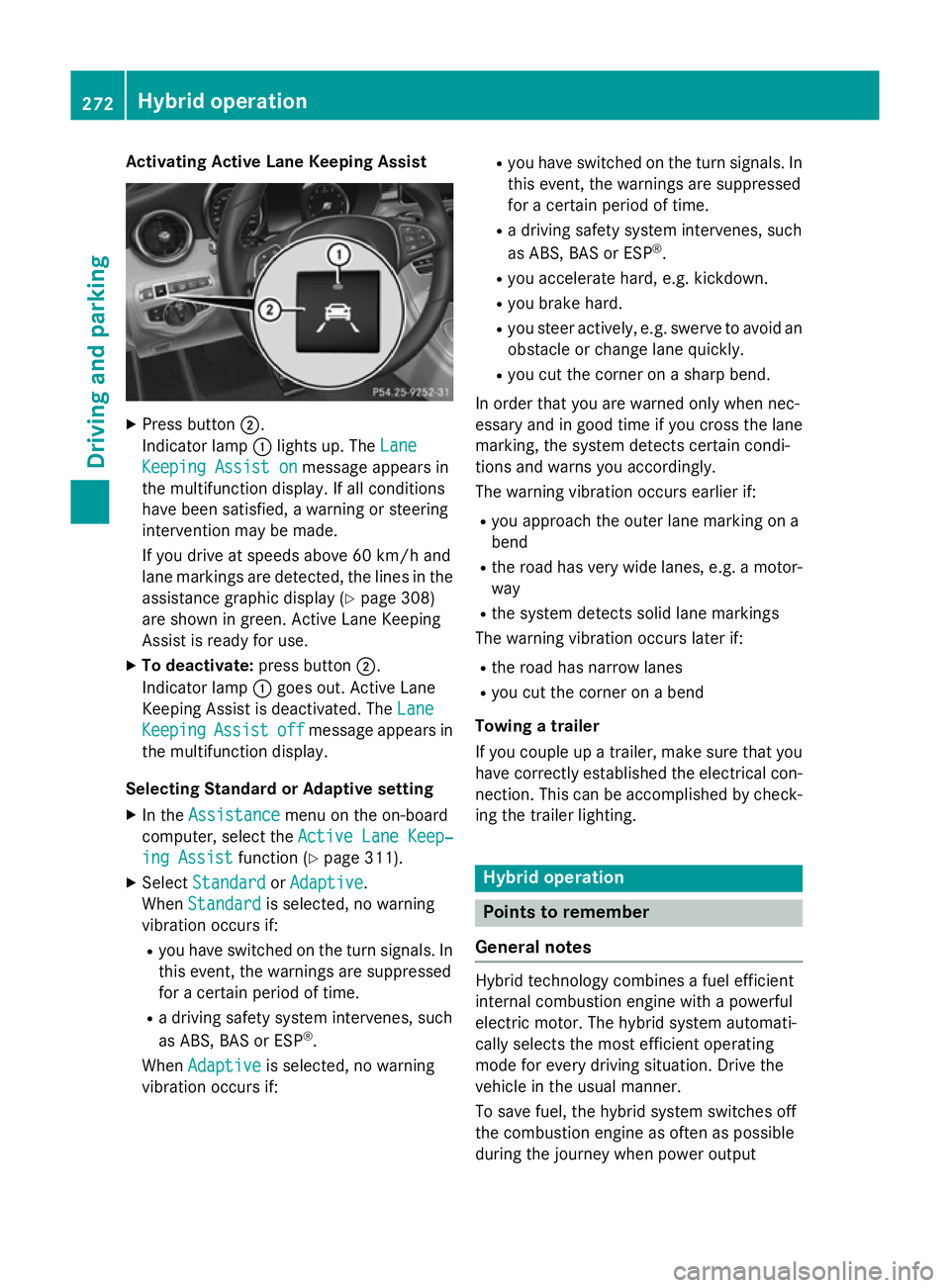
Activating Active Lane Keeping Assist
X
Press button ;.
Indicator lamp :lights up. The Lane
Lane
Keeping Assist on
Keeping Assist on message appears in
the multifunction display. If all conditions
have been satisfied, a warning or steering
intervention may be made.
If you drive at speeds above 60 km/h and
lane markings are detected, the lines in the assistance graphic display (Y page 308)
are shown in green. Active Lane Keeping
Assist is ready for use.
X To deactivate: press button;.
Indicator lamp :goes out. Active Lane
Keeping Assist is deactivated. The Lane Lane
Keeping
Keeping Assist
Assistoff
offmessage appears in
the multifunction display.
Selecting Standard or Adaptive setting X In the Assistance
Assistance menu on the on-board
computer, select the Active Lane Keep‐
Active Lane Keep‐
ing Assist
ing Assist function (Ypage 311).
X Select Standard
Standard orAdaptive
Adaptive.
When Standard
Standard is selected, no warning
vibration occurs if:
R you have switched on the turn signals. In
this event, the warnings are suppressed
for a certain period of time.
R a driving safety system intervenes, such
as ABS, BAS or ESP ®
.
When Adaptive
Adaptive is selected, no warning
vibration occurs if: R
you have switched on the turn signals. In
this event, the warnings are suppressed
for a certain period of time.
R a driving safety system intervenes, such
as ABS, BAS or ESP ®
.
R you accelerate hard, e.g. kickdown.
R you brake hard.
R you steer actively, e.g. swerve to avoid an
obstacle or change lane quickly.
R you cut the corner on a sharp bend.
In order that you are warned only when nec-
essary and in good time if you cross the lane marking, the system detects certain condi-
tions and warns you accordingly.
The warning vibration occurs earlier if:
R you approach the outer lane marking on a
bend
R the road has very wide lanes, e.g. a motor-
way
R the system detects solid lane markings
The warning vibration occurs later if:
R the road has narrow lanes
R you cut the corner on a bend
Towing a trailer
If you couple up a trailer, make sure that you have correctly established the electrical con- nection. This can be accomplished by check-
ing the trailer lighting. Hybrid operation
Points to remember
General notes Hybrid technology combines a fuel efficient
internal combustion engine with a powerful
electric motor. The hybrid system automati-
cally selects the most efficient operating
mode for every driving situation. Drive the
vehicle in the usual manner.
To save fuel, the hybrid system switches off
the combustion engine as often as possible
during the journey when power output 272
Hybrid operationDriving and pa
rking
Page 288 of 489
Problems with hybrid operation
Internal combustion engine Problem
Possible causes/consequences and
M
MSolutions You cannot start the
internal combustion
engine. The multifunc-
tion display shows no
display messages. The
READY indicator in the
multifunction display is
off. For example, the self-diagnosis is not yet complete or the hybrid
system is malfunctioning.
X Switch off the ignition and turn it back on.
X Try to start the internal combustion engine again.
If the internal combustion engine still does not start: X Consult a qualified specialist workshop. You wish to pull away,
but the ECO start/stop
function does not start
the internal combus-
tion engine. The READY
indicator in the multi-
function display is off. The ECO start/stop function has failed. The warning and indicator
lamps in the instrument cluster light up.
X Move the transmission selector lever to P.
X Switch off the ignition and turn it back on.
X Start the engine. The hybrid system is malfunctioning.
X Consult a qualified specialist workshop. Hybrid system
Problem
Possible causes/consequences and
M MSolutions The hybrid system was
deactivated automati-
cally. You have been in an accident.
The hybrid system remains deactivated if:
R the internal combustion engine cannot be restarted after a few
seconds.
R the red SRS warning lamp 6in the instrument cluster is lit.
X Consult a qualified specialist workshop. The hybrid system was
deactivated automati-
cally. The multifunction
display also shows a
display message. An electrical short circuit has occurred in the hybrid system or an
electrical connection has been disconnected.
X Observe the additional display messages in the multifunction
display (Y page 316).
X Consult a qualified specialist workshop. Hybrid operation
285Driving and parking Z
Page 291 of 489
level. When driving in mountainous areas,
note that the power output of the engine,
and consequently the vehicle's gradient-
climbing capability, decrease with increas-
ing altitude. Folding out the ball coupling
G
WARNING
If the ball coupling is not correctly engaged,
the trailer can detach. There is a risk of an
accident.
Always engage the ball coupling as described. G
WARNING
If you release the ball coupling or it does not
engage correctly when folding in, it will swing out. Within pivoting range of the ball coupling,
there is an increased risk of an accident and
injury.
Only release the ball coupling if the pivoting
range is unobstructed. Always make sure that the ball coupling engages when folding in.
Before you can tow a trailer with your vehicle, you must fold out the ball coupling.
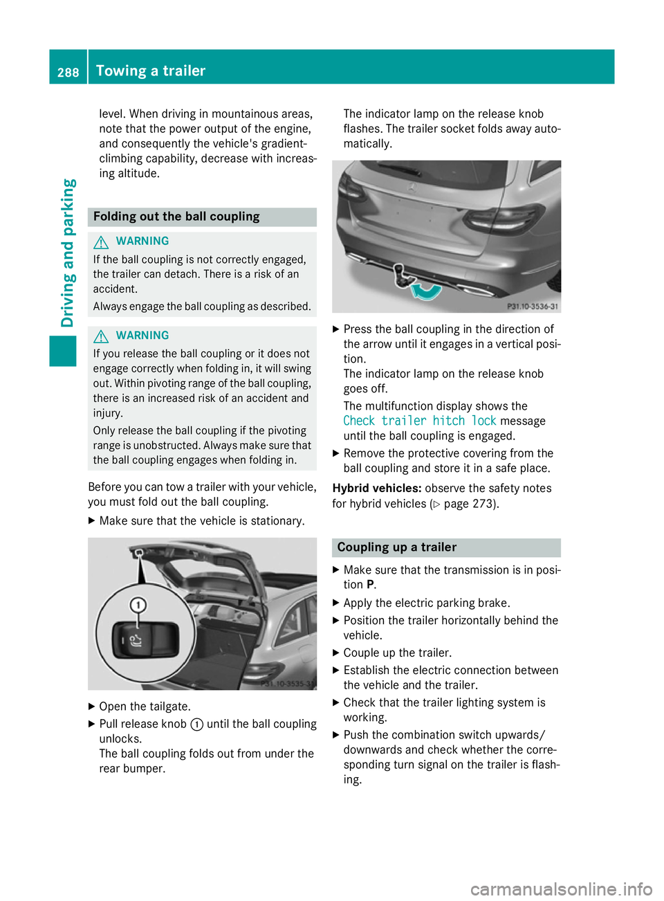
X Make sure that the vehicle is stationary. X
Open the tailgate.
X Pull release knob :until the ball coupling
unlocks.
The ball coupling folds out from under the
rear bumper. The indicator lamp on the release knob
flashes. The trailer socket folds away auto- matically. X
Press the ball coupling in the direction of
the arrow until it engages in a vertical posi-
tion.
The indicator lamp on the release knob
goes off.
The multifunction display shows the
Check trailer hitch lock Check trailer hitch lock message
until the ball coupling is engaged.
X Remove the protective covering from the
ball coupling and store it in a safe place.
Hybrid vehicles: observe the safety notes
for hybrid vehicles (Y page 273). Coupling up a trailer
X Make sure that the transmission is in posi-
tion P.
X Apply the electric parking brake.
X Position the trailer horizontally behind the
vehicle.
X Couple up the trailer.
X Establish the electric connection between
the vehicle and the trailer.
X Check that the trailer lighting system is
working.
X Push the combination switch upwards/
downwards and check whether the corre-
sponding turn signal on the trailer is flash-
ing. 288
Towing a trailerDriving and parking
Page 292 of 489
A connected trailer is only recognised when
the electrical connection is established
correctly and when the lighting system is
working properly. The functioning of other
systems, e.g. ESP ®
, PARKTRONIC, Active
Parking Assist, Active Blind Spot Assist or
Lane Keeping Assist also depends on this. Uncoupling a trailer
G
WARNING
If you uncouple a trailer with an engaged over- run brake, you could trap your hand between
the vehicle and the trailer drawbar. This poses a risk of injury.
Do not uncouple a trailer with an engaged
overrun brake. G
WARNING
Vehicles with level control:
If you disconnect the trailer cable, the vehicle is lowered. This can cause you or others to
become trapped between the vehicle body
and tyres, or underneath the vehicle. This
poses a risk of injury.
Make sure that no-one is in the immediate
vicinity of the wheel arch or underneath the
vehicle when disconnecting the trailer cable.
! Do not disconnect a trailer with an
engaged overrun brake. Otherwise, your
vehicle could be damaged by the rebound- ing of the overrun brake.
! Remove the installed adapter cable
before folding in the ball coupling. Other-
wise, damage may occur to the rear
bumper and the adapter cable.
X Make sure that the transmission is in posi-
tion P.
X Apply the electric parking brake.
X Secure the trailer against rolling away.
X Remove the trailer cable and decouple the
trailer. Folding in the ball coupling
G
WARNING
If you release the ball coupling or it does not
engage correctly when folding in, it will swing out. Within pivoting range of the ball coupling,
there is an increased risk of an accident and
injury.
Only release the ball coupling if the pivoting
range is unobstructed. Always make sure that the ball coupling engages when folding in.
Fold the ball coupling back in if you are not
using the trailer tow hitch. X Make sure that the vehicle is stationary and
the trailer cables are disconnected.
X Place the protective covering on the ball
coupling.
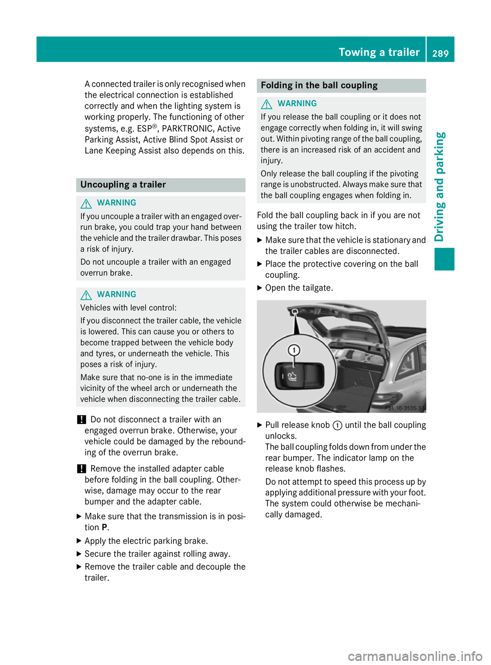
X Open the tailgate. X
Pull release knob :until the ball coupling
unlocks.
The ball coupling folds down from under the rear bumper. The indicator lamp on the
release knob flashes.
Do not attempt to speed this process up by
applying additional pressure with your foot. The system could otherwise be mechani-
cally damaged. Towing a trailer
289Driving and parking Z
Page 297 of 489
Useful information
i This Owner's Manual describes all mod-
els, series and optional equipment for your
vehicle that were available at the time of
going to press. National variations are pos- sible. Note that your vehicle may not be
equipped with all of the functions descri-
bed. This is also the case for systems and
functions relevant to safety.
i Read the information on qualified special-
ist workshops: (Y page 27). Important safety notes
G
WARNING
Operating the integrated information systems and communications equipment in the vehicle
while driving will distract you from traffic con-
ditions. You could then lose control of the
vehicle. There is a risk of an accident.
Only operate these devices if road traffic con-
ditions permit. If you are unsure about the
surrounding conditions, pull over to a safe
location and make entries only while the vehi-
cle is stationary.
You must observe the legal requirements for
the country in which you are currently driving when operating the on-board computer. G
WARNING
If the instrument cluster has failed or mal-
functioned, you may not recognise function
restrictions relevant to safety. The operating
safety of your vehicle may be impaired. There is a risk of an accident.
Drive on carefully. Have the vehicle checked
at a qualified specialist workshop immedi-
ately.
The on-board computer only shows messages
or warnings from certain systems in the mul- tifunction display. You should therefore make
sure your vehicle is operating safely at all
times. If the operating safety of your vehicle is
impaired, park the vehicle safely as soon as
possible. Contact a qualified specialist work-
shop.
For an overview, see the instrument cluster
illustration (Y
page 34). Displays and operation
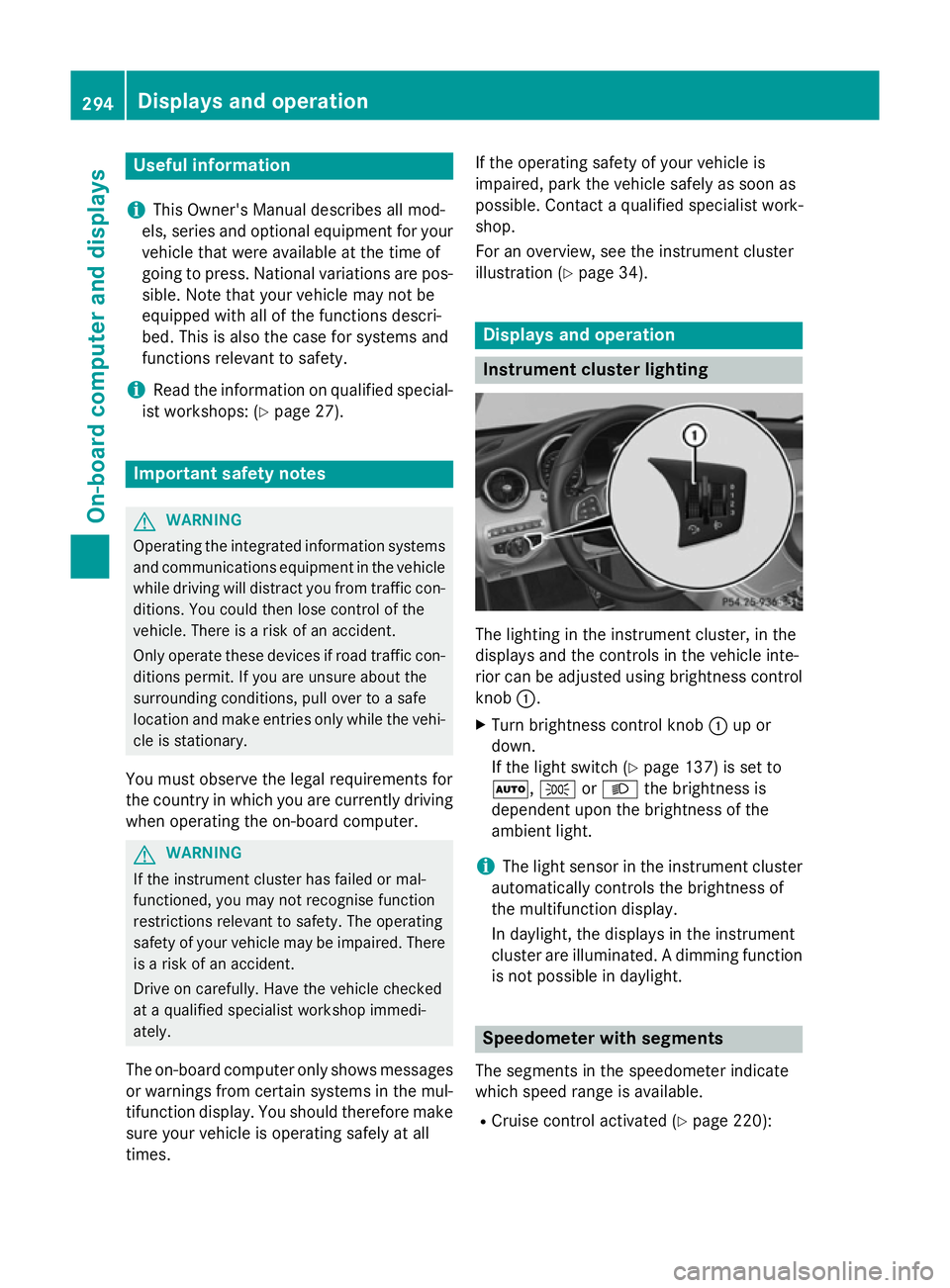
Instrument cluster lighting
The lighting in the instrument cluster, in the
displays and the controls in the vehicle inte-
rior can be adjusted using brightness control
knob :.
X Turn brightness control knob :up or
down.
If the light switch (Y page 137) is set to
Ã, TorL the brightness is
dependent upon the brightness of the
ambient light.
i The light sensor in the instrument cluster
automatically controls the brightness of
the multifunction display.
In daylight, the displays in the instrument
cluster are illuminated. A dimming function
is not possible in daylight. Speedometer with segments
The segments in the speedometer indicate
which speed range is available. R Cruise control activated (Y page 220):294
Displays and operationOn-board computer and displays
Page 298 of 489
The segments light up from the stored
speed to the maximum speed.
R Variable SPEEDTRONIC activated
(Y page 223):
The segments light up from the start of the
scale to the selected limit speed.
R DISTRONIC PLUS activated (Y page 226):
One or two segments in the set speed
range light up.
R DISTRONIC PLUS detects a vehicle in front
that is driving at a slower speed than the
stored speed:
The segments between the speed of the
vehicle in front and the stored speed light
up. Rev counter
! Do not drive in the overrevving range.
Doing so will damage the engine.
The red band in the rev counter indicates the engine's overrevving range.
The fuel supply is interrupted to protect the
engine when the red band is reached. Outside temperature display
You should pay special attention to road con- ditions when temperatures are around the
freezing point.
Bear in mind that the outside temperature
display indicates the temperature measured
and does not record the road temperature.
The outside temperature display is in the mul-
tifunction display (Y page 297).
Changes in the outside temperature are dis-
played after a short delay. Coolant temperature gauge
G
WARNING
If you open the bonnet while the engine is
overheating or while there is a fire in the
engine compartment, you could come into contact with hot gases or other leaking ser-
vice products. There is a danger of injury.
Allow an overheating engine to cool down
before opening the bonnet. If there is a fire in
the engine compartment, leave the bonnet
closed and notify the fire brigade.
The analogue coolant temperature gauge is in
the instrument cluster on the right-hand side (Y page 34).
In the on-board computer in the Service Service
menu there is a digital coolant temperature
gauge (Y page 309).
Under normal operating conditions and with
the specified coolant level, the coolant tem-
perature may rise to 120 †.
At high outside temperatures and when driv-
ing uphill, the coolant temperature may rise
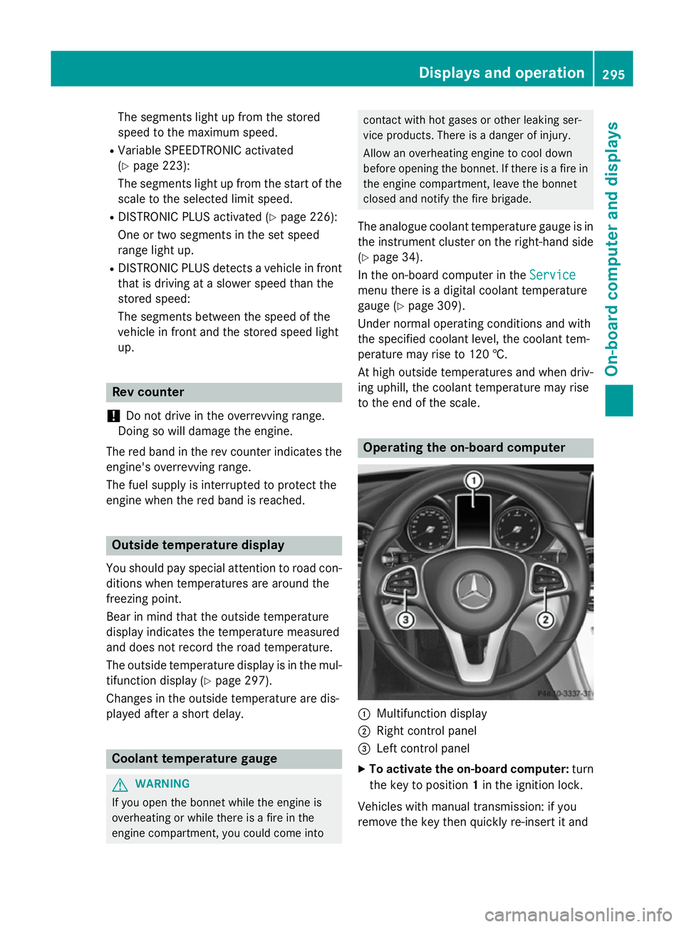
to the end of the scale. Operating the on-board computer
:
Multifunction display
; Right control panel
= Left control panel
X To activate the on-board computer: turn
the key to position 1in the ignition lock.
Vehicles with manual transmission: if you
remove the key then quickly re-insert it and Displays and operation
295On-board computer and displays Z
Page 312 of 489
Displaying the coolant temperature
The coolant temperature is also shown in the
instrument cluster in the rev counter.
Observe the notes on coolant temperature
(Y page 295).
X Use ò on the steering wheel to call up
the list of menus.
X Press the :or9 button on the steer-
ing wheel to select the Service Servicemenu.
X Confirm by pressing aon the steering
wheel.
X Use : or9 to select the Coolant Coolant
submenu.
X Press ato confirm your selection.
The coolant temperature is shown in a bar
display.
Displaying AdBlue ®
level and range This menu is only available in BlueTEC vehi-
cles.
X Use ò on the steering wheel to call up
the list of menus.
X Press the :or9 button on the steer-
ing wheel to select the Service
Service menu.
X Confirm by pressing aon the steering
wheel.
X Select the AdBlue AdBluesubmenu using :or
9.
X Press ato confirm your selection.
The range and AdBlue ®
level appear in a bar
graph in the multifunction display.
Observe the information and notes on "Refu- elling" (Y page 208). Settings menu
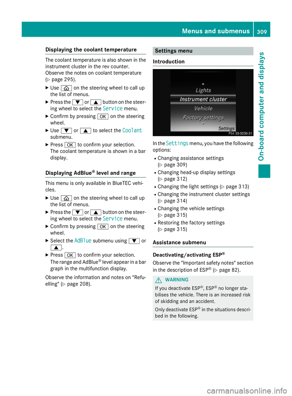
Introduction In the
Settings
Settings menu, you have the following
options:
R Changing assistance settings
(Y page 309)
R Changing head-up display settings
(Y page 312)
R Changing the light settings (Y page 313)
R Changing the instrument cluster settings
(Y page 314)
R Changing the vehicle settings
(Y page 315)
R Restoring the factory settings
(Y page 315)
Assistance submenu Deactivating/activating ESP
®
Observe the "Important safety notes" section
in the description of ESP ®
(Y page 82). G
WARNING
If you deactivate ESP ®
, ESP ®
no longer sta-
bilises the vehicle. There is an increased risk
of skidding and an accident.
Only deactivate ESP ®
in the situations descri-
bed in the following. Menus and submenus
309On-boardcompu ter and displays Z