Page 422 of 457
749
Maintenance
If you do not have a spare, use afuse of the same rating from a circuityou may not need for operating thevehicle, such as the power outletfuse.
If the headlights or other electrical
components do not work and the
fuses are OK, check the fuse panel
in the engine compartment. If a fuse
is blown, it must be replaced.
G210101AHM-C1
Memory fuse
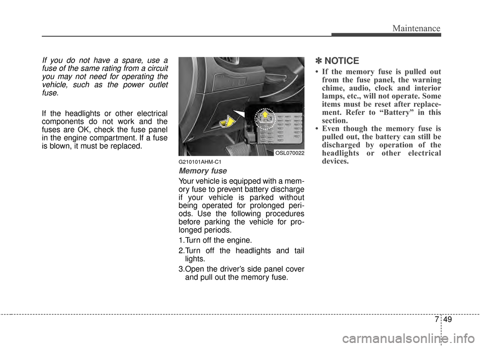
Your vehicle is equipped with a mem-
ory fuse to prevent battery discharge
if your vehicle is parked without
being operated for prolonged peri-
ods. Use the following procedures
before parking the vehicle for pro-
longed periods.
1.Turn off the engine.
2.Turn off the headlights and tail lights.
3.Open the driver’s side panel cover and pull out the memory fuse.
✽ ✽ NOTICE
• If the memory fuse is pulled out
from the fuse panel, the warning
chime, audio, clock and interior
lamps, etc., will not operate. Some
items must be reset after replace-
ment. Refer to “Battery” in this
section.
• Even though the memory fuse is pulled out, the battery can still be
discharged by operation of the
headlights or other electrical
devices.
OSL070022
Page 423 of 457
Maintenance
50
7
G210200AHM
❈ The actual feature may differ from the
illustration.
Engine compartment fuse
replacement
1.Turn the ignition switch and all other switches off.
2.Remove the fuse panel cover by pressing the tab and pulling the
cover up. 3.Check the removed fuse; replace it
if it is blown. To remove or insert
the fuse, use the fuse puller in the
engine compartment fuse panel.
4.Push in a new fuse of the same rat- ing, and make sure it fits tightly in
the clips.
If it fits loosely, consult an author-
ized Kia dealer.
G210201AAM
Main fuse and multi fuse
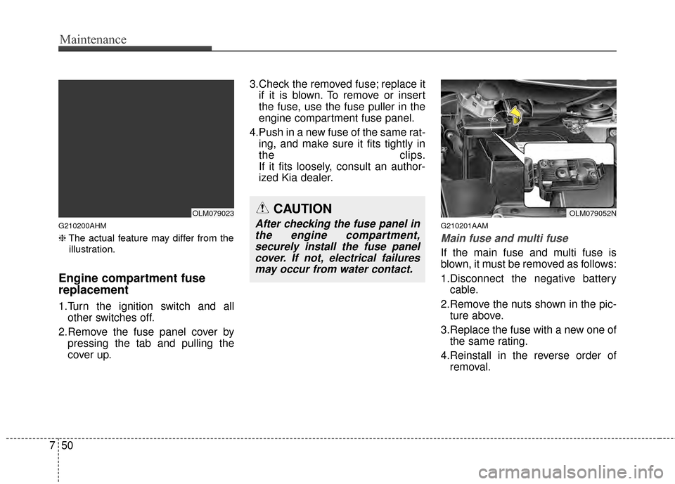
If the main fuse and multi fuse is
blown, it must be removed as follows:
1.Disconnect the negative batterycable.
2.Remove the nuts shown in the pic- ture above.
3.Replace the fuse with a new one of the same rating.
4.Reinstall in the reverse order of removal.
CAUTION
After checking the fuse panel inthe engine compartment,securely install the fuse panelcover. If not, electrical failuresmay occur from water contact.
OLM079052NOLM079023
Page 426 of 457
753
Maintenance
Engine compartment fuse
panel
✽ ✽NOTICE
The actual fuse/relay panel label
may differ from equipped items.
OSL074202N
OLM079027N
Page 427 of 457
Maintenance
54
7
Engine compartment fuse
panel
✽ ✽
NOTICE
The actual fuse/relay panel label
may differ from equipped items.
OLM079053N
OSL074103
Page 430 of 457
757
Maintenance
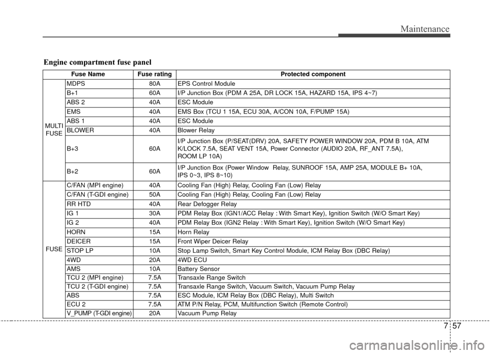
Engine compartment fuse panel
Fuse NameFuse rating Protected component
MULTI FUSE MDPS
80A EPS Control Module
B+1 60A I/P Junction Box (PDM A 25A, DR LOCK 15A, HAZARD 15A, IPS 4~7)
ABS 2 40A ESC Module
EMS 40A EMS Box (TCU 1 15A, ECU 30A, A/CON 10A, F/PUMP 15A)
ABS 1 40A ESC Module
BLOWER 40A Blower Relay
B+3 60AI/P Junction Box (P/SEAT(DRV) 20A, SAFETY POWER WINDOW 20A, PDM B 10A, ATM
K/LOCK 7.5A, SEAT VENT 15A, Power Connector (AUDIO 20A, RF_ANT 7.5A),
ROOM LP 10A)
B+2 60AI/P Junction Box (Power Window Relay, SUNROOF 15A, AMP 25A, MODULE B+ 10A,
IPS 0~3, IPS 8~10)
FUSE C/FAN (MPI engine) 40A Cooling Fan (High) Relay, Cooling Fan (Low) Relay
C/FAN (T-GDI engine) 50A Cooling Fan (High) Relay, Cooling Fan (Low) Relay
RR HTD
40A Rear Defogger Relay
IG 1 30A PDM Relay Box (IGN1/ACC Relay : With Smart Key), Ignition Switch (W/O Smart Key)
IG 2 40A PDM Relay Box (IGN2 Relay : With Smart Key), Ignition Switch (W/O Smart Key)
HORN 15A Horn Relay
DEICER 15A Front Wiper Deicer Relay
STOP LP 10A Stop Lamp Switch, Smart Key Control Module, ICM Relay Box (DBC Relay)
4WD 20A 4WD ECU
AMS 10A Battery Sensor
TCU 2 (MPI engine) 7.5A Transaxle Range Switch
TCU 2 (T-GDI engine) 7.5A Transaxle Range Switch, Vacuum Switch, Vacuum Pump Relay
ABS 7.5A ESC Module, ICM Relay Box (DBC Relay), Multi Switch
ECU 2 7.5A ATM P/N Relay, PCM, Multifunction Switch (Remote Control)
V_PUMP (T-GDI engine) 20A V acuum Pump Relay
Page 431 of 457
Maintenance
58
7
Fuse Name Fuse rating Protected component
F/PUMP 15A Fuel Pump Relay
SENSOR 4 15AFuel Pump Relay, PCM, Oxygen Sensor (Up)/(Down),
E/R Fuse & Relay Box (Cooling Fan (High)/(Low) Relay)
SENSOR 3 10A A/CON Relay, Injector #1~#4
SENSOR 2 10A (Not Used)
TCU 1 15A PCM
A/CON 10A A/CON Relay
SENSOR 1 (MPI engine) 10A Immobilizer Module, Crankshaft Position Sensor, Camshaft Position Sensor #1/#2, Oil Control Valve
#1/#2Canister Purge Control Solenoid Valve, Variable Intake Solenoid Valve, Canister Close Valve
SENSOR 1 (T-GDI engine) 10A Immobilizer Module, Crankshaft Position Sensor, Camshaft Position Sensor #1/#2, Oil Control Valve
#1/#2Canister Purge Control Solenoid Valve, Variable Intake Solenoid Valve, Canister Close Valve,
RCV
ECU 1 20A Ignition Coil #1~#4, Condenser
ECU 30A Engine Control Relay
Engine compartment main fuse panel (EMS Box)
Page 433 of 457
Maintenance
60
7
Waxing
Wax the vehicle when water will no
longer bead on the paint.
Always wash and dry the vehicle
before waxing. Use a good quality
liquid or paste wax, and follow the
manufacturer’s instructions. Wax all
metal trim to protect it and to main-
tain its luster.
Removing oil, tar, and similar materi-
als with a spot remover will usually
strip the wax from the finish. Be sure
to re-wax these areas even if the rest
of the vehicle does not yet need wax-
ing.
CAUTION
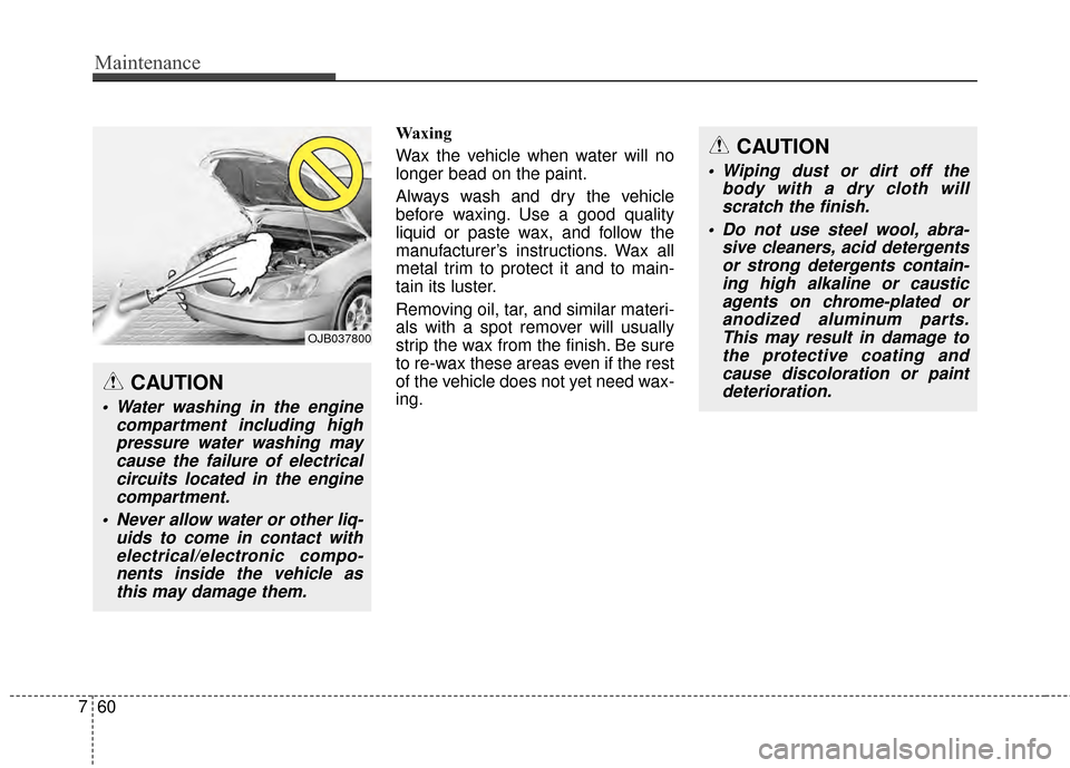
Water washing in the engine
compartment including highpressure water washing maycause the failure of electricalcircuits located in the enginecompartment.
Never allow water or other liq- uids to come in contact withelectrical/electronic compo-nents inside the vehicle asthis may damage them.
CAUTION
Wiping dust or dirt off the body with a dry cloth willscratch the finish.
Do not use steel wool, abra- sive cleaners, acid detergentsor strong detergents contain-ing high alkaline or causticagents on chrome-plated oranodized aluminum parts.This may result in damage tothe protective coating andcause discoloration or paintdeterioration.
OJB037800
Page 440 of 457
767
Maintenance
G270201AUN
Canister
Fuel vapors generated inside the fuel
tank are absorbed and stored in the
onboard canister. When the engine is
running, the fuel vapors absorbed in
the canister are drawn into the surge
tank through the purge control sole-
noid valve.
G270202AHM
Purge Control Solenoid Valve(PCSV)
The purge control solenoid valve is
controlled by the Engine Control
Module (ECM); when the engine
coolant temperature is low during
idling, the PCSV closes so that evap-
orated fuel is not taken into the
engine. After the engine warms up
during ordinary driving, the PCSV
opens to introduce evaporated fuel to
the engine.
G270300AUN
3. Exhaust emission control system
The Exhaust Emission Control
System is a highly effective system
which controls exhaust emissions
while maintaining good vehicle per-
formance.
G270301AUN
Vehicle modifications
This vehicle should not be modified.
Modification of your vehicle could
affect its performance, safety or
durability and may even violate gov-
ernmental safety and emissions reg-
ulations.
In addition, damage or performance
problems resulting from any modifi-
cation may not be covered under
warranty.
If you use unauthorized electronic
devices, it may cause the vehicle to
operate abnormally, wire damage,
battery discharge or fire. For your
safety, do not use unauthorized
electronic devices.
G270302AUN-EU
Engine exhaust gas precautions
(carbon monoxide)
Carbon monoxide can be present with other exhaust fumes.
Therefore, if you smell exhaust
fumes of any kind inside your vehi-
cle, have it inspected and repaired
immediately. If you ever suspect
exhaust fumes are coming into
your vehicle, drive it only with all
the windows fully open. Have your
vehicle checked and repaired
immediately.
WARNING - Exhaust
Engine exhaust gases contain
carbon monoxide (CO). Though
colorless and odorless, it is
dangerous and could be lethal if
inhaled. Follow the instructions
on this page to avoid CO poi-
soning.