2014 JEEP CHEROKEE instrument cluster
[x] Cancel search: instrument clusterPage 3 of 204

INTRODUCTION/WELCOME
WELCOME FROM CHRYSLER
GROUP LLC.................. 3
CONTROLS AT A GLANCE
DRIVER COCKPIT .............. 6
INSTRUMENT CLUSTER .......... 8
GETTING STARTED
KEYFOB ................... 10
REMOTE START............... 12
VEHICLE SECURITY ALARM ....... 13
KEYLESS ENTER-N-GO™ ......... 14
SEATBELT .................. 18
SUPPLEMENTAL RESTRAINT SYSTEM
(SRS) — AIR BAGS ............ 19
CHILD RESTRAINTS ............ 20
FRONT SEATS ................ 25
REAR SEATS ................ 27
HEATED/VENTILATED SEATS ....... 28
HEATED STEERING WHEEL ....... 29
TILT/TELESCOPING STEERING
COLUMN ................... 30
OPERATING YOUR VEHICLE
ENGINE BREAK-IN
RECOMMENDATIONS ........... 31
TURN SIGNAL/HIGH BEAM LEVER . . . 31
HEADLIGHT SWITCH ............ 32
WIPER/WASHER LEVER .......... 33
SPEED CONTROL .............. 34
ADAPTIVE CRUISE CONTROL (ACC) . . . 36
FORWARD COLLISION WARNING (FCW)
WITHMITIGATION ............. 39
MANUAL CLIMATE CONTROLS WITHOUT
TOUCHSCREEN ............... 41
MANUAL CLIMATE CONTROLS WITH
TOUCHSCREEN ............... 42
AUTOMATIC TEMPERATURE
CONTROLS (ATC) .............. 43
ELECTRIC PARK BRAKE .......... 45
PARKSENSE
®................ 46
LANESENSE ................. 48
PARKVIEW
®REAR BACK-UP
CAMERA ................... 49
POWER SUNROOF ............. 50
WIND BUFFETING ............. 53
ELECTRONICS
YOUR VEHICLE'S SOUND SYSTEM . . . 54
IDENTIFYING YOUR RADIO ........ 56
Uconnect
®ACCESS ............. 57 Uconnect
®5.0 ................ 73
Uconnect®8.4A ............... 81
Uconnect®8.4AN ............. 100
STEERING WHEEL AUDIO
CONTROLS ................. 120
ELECTRONIC VEHICLE INFORMATION
CENTER (EVIC) .............. 121
PROGRAMMABLE FEATURES ...... 122
UNIVERSAL GARAGE DOOR OPENER
(HomeLink
®) ................ 122
POWER INVERTER ............ 125
POWER OUTLET ............. 126
WIRELESS CHARGING PAD ....... 128
OFF-ROAD CAPABILITIES
FOUR-WHEEL DRIVE OPERATION . . . 131
SELEC-TERRAIN™............ 134
UTILITY
CARGO AREA FEATURES ........ 135
TRAILER TOWING WEIGHTS (MAXIMUM
TRAILER WEIGHT RATINGS) ...... 135
RECREATIONAL TOWING (BEHIND
MOTORHOME, ETC.) ........... 136
WHATTODOIN
EMERGENCIES
ROADSIDE ASSISTANCE ......... 141
INSTRUMENT CLUSTER WARNING
LIGHTS ................... 141
INSTRUMENT CLUSTER INDICATOR
LIGHTS ................... 148
IF YOUR ENGINE OVERHEATS ..... 151
TIREFIT KIT ................ 151
JACKING AND TIRE CHANGING .... 158
JUMP-STARTING ............. 163
FREEING A STUCK VEHICLE ...... 166
RECOVERY STRAP ............ 167
SHIFT LEVER OVERRIDE ........ 167
TOWING A DISABLED VEHICLE .... 168
EVENT DATA RECORDER (EDR) .... 169
MAINTAINING YOUR VEHICLE
OPENING THE HOOD.......... 170
ENGINE COMPARTMENT ........ 171
FLUIDS AND CAPACITIES ........ 173
MAINTENANCE SCHEDULE ...... 175
FUSES .................... 179
TIRE PRESSURES ............. 184
WHEEL AND WHEEL TRIM CARE . . . 185
REPLACEMENT BULBS ......... 185
TABLE OF CONTENTS
Page 10 of 204

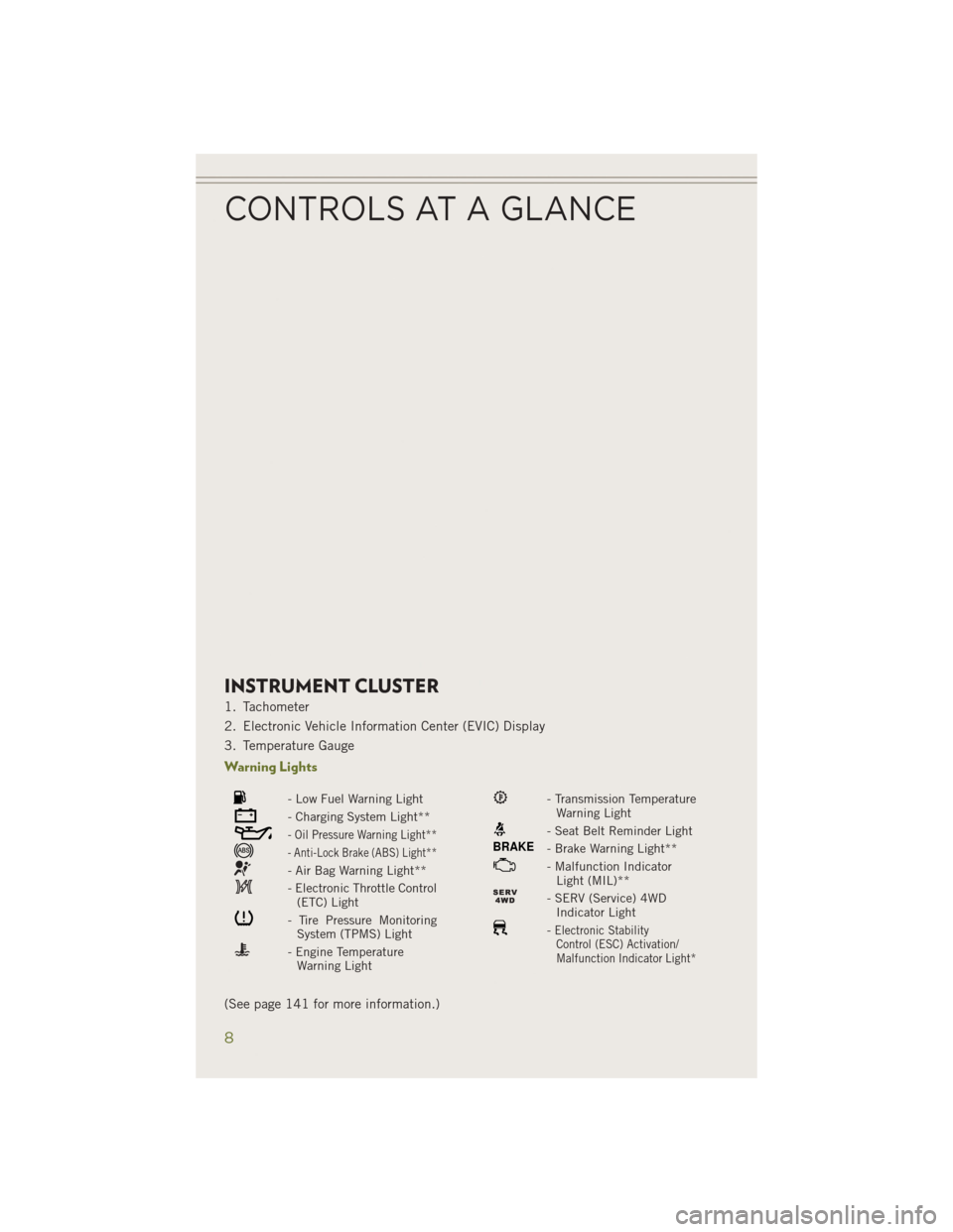
INSTRUMENT CLUSTER
1. Tachometer
2. Electronic Vehicle Information Center (EVIC) Display
3. Temperature Gauge
Warning Lights
- Low Fuel Warning Light
- Charging System Light**
- Oil Pressure Warning Light**
- Anti-Lock Brake (ABS) Light**
- Air Bag Warning Light**
- Electronic Throttle Control(ETC) Light
- Tire Pressure MonitoringSystem (TPMS) Light
- Engine TemperatureWarning Light
- Transmission TemperatureWarning Light
- Seat Belt Reminder Light
BRAKE- Brake Warning Light**
- Malfunction IndicatorLight (MIL)**
- SERV (Service) 4WDIndicator Light
-Electronic StabilityControl (ESC) Activation/
Malfunction Indicator Light*
(See page 141 for more information.)
CONTROLS AT A GLANCE
8
Page 15 of 204

VEHICLE SECURITY ALARM
To Arm:
• Lock the door using either the power door lock switch (one door must be open) orthe LOCK button on the Remote Keyless Entry (RKE) transmitter (doors can be
open or closed), and close all doors.
The Vehicle Security Light in the instrument cluster will flash for 16 seconds. This
shows that the Vehicle Security Alarm is arming. During this period, if a door is
opened, the ignition is cycled to ON/RUN, or the power door locks are unlocked in any
manner, the Vehicle Security Alarm will automatically disarm.
NOTE:
• The Vehicle Security Alarm will not arm if you lock the doors with the manual door lock plungers.
• Once armed, the Vehicle Security Alarm disables the unlock switch on the driver door trim panel and passenger door trim panel.
To Disarm The System:
• Push the Key Fob UNLOCK button or cycle the ignition to the ON/RUN position.
The Vehicle Security Alarm is designed to protect your vehicle; however, you can
create conditions where the Vehicle Security Alarm will give you a false alarm. If one
of the previously described arming sequences has occurred, the Vehicle Security
Alarm will arm regardless of whether you are in the vehicle or not. If you remain in the
vehicle and open a door, the alarm will sound. If this occurs, disarm the Vehicle
Security Alarm.
If the Vehicle Security Alarm is armed and the battery becomes disconnected the
Vehicle Security Alarm will remain armed when the battery is reconnected. The
exterior lights will flash, and the horn will sound. If this occurs, disarm the Vehicle
Security Alarm.
GETTING STARTED
13
Page 36 of 204

SPEED CONTROL
The Speed Control switches are located on the right side of the steering wheel.
Cruise ON/OFF
• Push the ON/OFF buttonto acti-
vate the Speed Control.
CRUISE CONTROL READY will appear
on the instrument cluster to indicate the
Speed Control is on.
• Push the ON/OFF button
a sec-
ond time to turn the system off.
CRUISE CONTROL OFF will appear on
the instrument cluster to indicate the
Speed Control is off.
SET
• With the Speed Control on, push and release the SET+ or SET- button to set
a desired speed.
Once a speed has been set a message
CRUISE CONTROL SET TO MPH/KM will appear indicating what speed was set. An
indicator CRUISE will also appear and stay on in the instrument cluster when the
speed is set.
Accel/Decel
To Increase Speed
• When the Electronic Speed Control is set, you can increase speed by pushing the SET +button.
The speed increment shown is dependant on the speed of U.S. (mph) or Metric
(km/h) units:
U.S. Speed (mph)
• Pressing the SET +button once will result in a 1 mph increase in set speed. Each
subsequent tap of the button results in an increase of 1 mph.
• If the button is continually pressed, the set speed will continue to increase until the button is released, then the new set speed will be established.
Metric Speed (km/h)
• Pressing the SET +button once will result in a 1 km/h increase in set speed. Each
subsequent tap of the button results in an increase of 1 km/h.
• If the button is continually pressed, the set speed will continue to increase until the button is released, then the new set speed will be established.
Speed Control Switches
1 — Push Cancel
2 — Push Set+/Accel
3 — Push Resume
4 — Push On/Off
5 — Push Set-/Decel
OPERATING YOUR VEHICLE
34
Page 38 of 204

ADAPTIVE CRUISE CONTROL (ACC)
If your vehicle is equipped with adaptive
cruise control the controls operate ex-
actly the same as the normal (fixed
speed) speed control with one difference.
You can set a specified distance you
would like to maintain between you and
the vehicle in front of you.
If the ACC sensor detects a vehicle
ahead, ACC will apply limited braking or
acceleration automatically to maintain a
preset following distance, while match-
ing the speed of the vehicle ahead.
If the sensor does not detect a vehicle
ahead of you, ACC will maintain a fixed
set speed.
ACC ON/OFF
• Push and release the Adaptive Cruise Control (ACC) ON/OFF button.
ACC READY will appear on the instrument cluster to indicate the ACC is on.
• Push and release the Adaptive Cruise Control (ACC) ON/OFF button a second timeto turn the system off.
Adaptive Cruise Control (ACC) Off will appear on the instrument cluster to indicate
the ACC is off.
Distance Setting (ACC Only)
The specified following distance for ACC can be set by varying the distance setting
between four bars (longest), three bars (long), two bars (medium) and one bar (short).
Using this distance setting and the vehicle speed, ACC calculates and sets the
distance to the vehicle ahead. This distance setting displays in the EVIC.
• To increase the distance setting, press the Distance Setting—Increase button and release. Each time the button is pressed, the distance setting increases by one bar
(longer).
• To decrease the distance setting, press the Distance Setting—Decrease button and release. Each time the button is pressed, the distance setting decreases by
one bar (shorter).
Adaptive Cruise Switches
1 — Adaptive Cruise Control (ACC)
On/Off
2 — Distance Setting – Decrease
3 — Distance Setting – Increase
OPERATING YOUR VEHICLE
36
Page 50 of 204

WARNING!
• Drivers must be careful when backing up even when using ParkSense®. Always
check carefully behind your vehicle, look behind you, and be sure to check for
pedestrians, animals, other vehicles, obstructions, and blind spots before
backing up. You are responsible for safety and must continue to pay attention
to your surroundings. Failure to do so can result in serious injury or death.
• Before using ParkSense
®, it is strongly recommended that the ball mount and
hitch ball assembly is disconnected from the vehicle when the vehicle is not
used for towing. Failure to do so can result in injury or damage to vehicles or
obstacles because the hitch ball will be much closer to the obstacle than the
rear fascia when the loudspeaker sounds the continuous tone. Also, the sensors
could detect the ball mount and hitch ball assembly, depending on its size and
shape, giving a false indication that an obstacle is behind the vehicle.
LANESENSE
The LaneSense system can be enabled and disabled with the LaneSense button,
located on the switch panel below the Uconnect®display.
• Press the LaneSense button to turn the system ON (LED turns off).
The LaneSense system is operational at
speeds above 37 mph (60 km/h) and
below 112 mph (180 km/h). The La-
neSense system uses a forward looking
camera to detect lane markings and mea-
sure vehicle position within the lane
boundaries.
When both lane markings are detected
and the driver unintentionally drifts out
of the lane (no turn signal applied), the
LaneSense system provides a haptic
warning in the form of torque applied to
the steering wheel to prompt the driver to
remain within the lane boundaries. If the driver continues to unintentionally drift out
of the lane, the LaneSense system provides a visual warning through the instrument
cluster to prompt the driver to remain within the lane boundaries.
LaneSense Button
OPERATING YOUR VEHICLE
48
Page 51 of 204

The driver may manually override the haptic warning by applying torque into the
steering wheel at any time.
When only a single lane marking is detected and the driver unintentionally drifts
across the lane marking (no turn signal applied), the LaneSense system provides a
visual warning through the instrument cluster to prompt the driver to remain within
the lane. When only a single lane marking is detected, a haptic (torque) warning will
not be provided.
Refer to your Owner's Manual on the DVD for further details.
NOTE:
When operating conditions have been met, the LaneSense system will monitor if the
driver’s hands are on the steering wheel and provides an audible warning to the driver
when the driver’s hands are not detected on the steering wheel. The system will
cancel if the driver does not return their hands to the wheel.
PARKVIEW® REAR BACK-UP CAMERA
You can see an on-screen image of the rear of your vehicle whenever the shift lever is
put into REVERSE. The ParkView®Rear Back-Up Camera image will be displayed on
the radio display screen, located on the center stack of the instrument panel.
If the radio display screen appears foggy, clean the camera lens located on the rear
of the vehicle above the rear license plate.
Refer to your Owner's Manual on the DVD for further details.
WARNING!
Drivers must be careful when backing up; even when using the ParkView®Rear
Back-Up Camera. Always check carefully behind your vehicle, and be sure to
check for pedestrians, animals, other vehicles, obstructions, or blind spots before
backing up. You must continue to pay attention while backing up. Failure to do so
can result in serious injury or death.
OPERATING YOUR VEHICLE
49
Page 123 of 204

ELECTRONIC VEHICLE INFORMATION
CENTER (EVIC)
•The EVIC features a driver interactive
display that is located in the instrument
cluster. Pushing the controls on the left
side of the steering wheel allows the
driver to select vehicle information and
Personal Settings. For additional infor-
mation, refer to Programmable Features
in this guide.
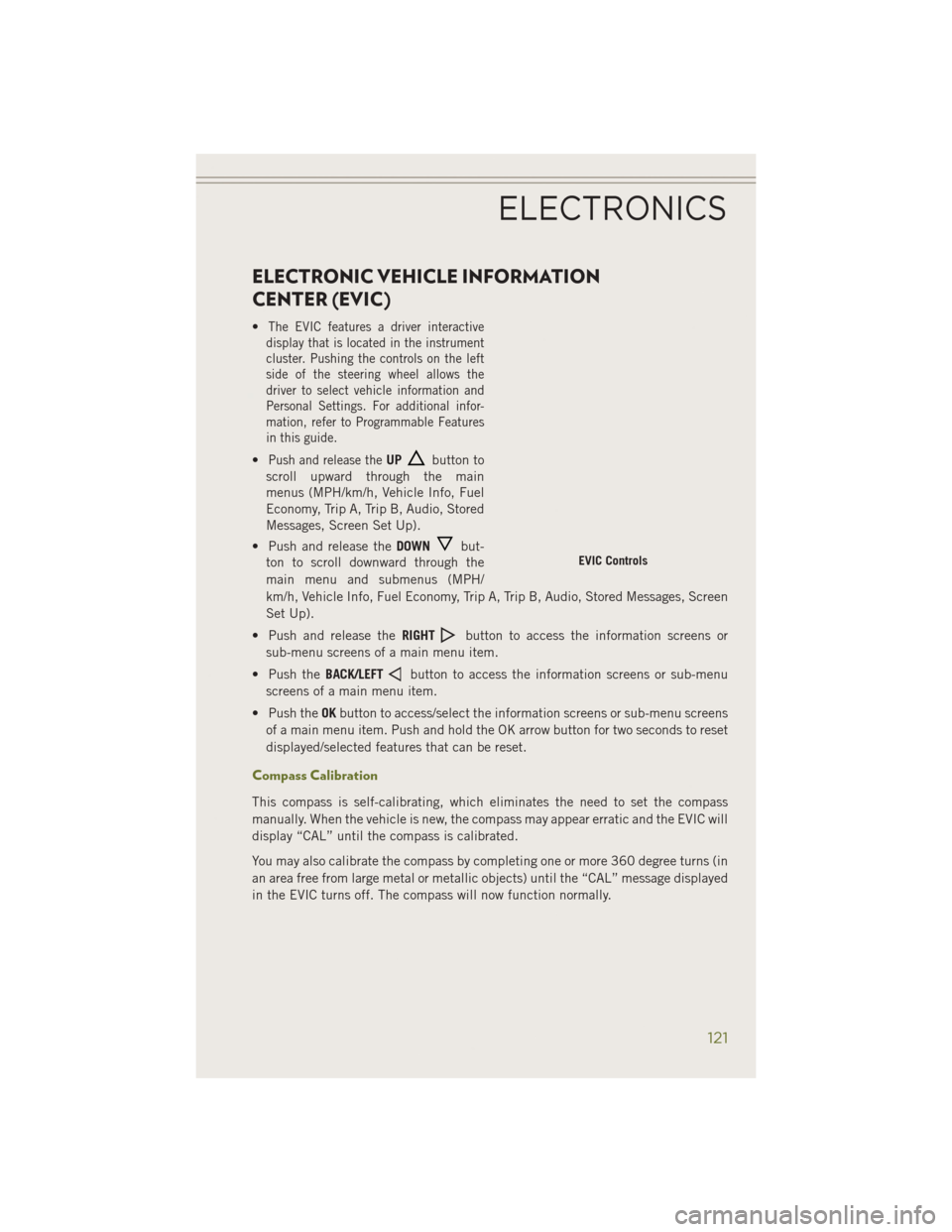
•Push and release theUPbutton to
scroll upward through the main
menus (MPH/km/h, Vehicle Info, Fuel
Economy, Trip A, Trip B, Audio, Stored
Messages, Screen Set Up).
• Push and release the DOWN
but-
ton to scroll downward through the
main menu and submenus (MPH/
km/h, Vehicle Info, Fuel Economy, Trip A, Trip B, Audio, Stored Messages, Screen
Set Up).
• Push and release the RIGHT
button to access the information screens or
sub-menu screens of a main menu item.
• Push the BACK/LEFT
button to access the information screens or sub-menu
screens of a main menu item.
• Push the OKbutton to access/select the information screens or sub-menu screens
of a main menu item. Push and hold the OK arrow button for two seconds to reset
displayed/selected features that can be reset.
Compass Calibration
This compass is self-calibrating, which eliminates the need to set the compass
manually. When the vehicle is new, the compass may appear erratic and the EVIC will
display “CAL” until the compass is calibrated.
You may also calibrate the compass by completing one or more 360 degree turns (in
an area free from large metal or metallic objects) until the “CAL” message displayed
in the EVIC turns off. The compass will now function normally.
EVIC Controls
ELECTRONICS
121