2014 Hyundai Sonata service
[x] Cancel search: servicePage 581 of 665

7-24
Maintenance
Va c u u m c r a n k c a s e v e n t i l a t i o n
hoses (if equipped)
Inspect the surface of hoses for evi-
dence of heat and/or mechanical
damage. Hard and brittle rubber,
cracking, tears, cuts, abrasions, and
excessive swelling indicate deterio-
ration. Particular attention should be
paid to examine those hose surfaces
nearest to high heat sources, such
as the exhaust manifold.
Inspect the hose routing to assure
that the hoses do not come in con-
tact with any heat source, sharp
edges or moving component which
might cause heat damage or mechan-
ical wear. Inspect all hose connec-
tions, such as clamps and couplings,
to make sure they are secure, and that
no leaks are present. Hoses should be
replaced immediately if there is any
evidence of deterioration or damage.
Air cleaner filter
We recommend that the air cleaner
filter be replaced by an authorized
HYUNDAI dealer.
Spark plugs
Make sure to install new spark plugs
of the correct heat range.
Va l v e cl e a r a n c e ( T h e t a E n g i n e )
Inspect excessive valve noise and/or
engine vibration and adjust if neces-
sary. We recommend that the system
be serviced by an authorized
HYUNDAI dealer.
Cooling system
Check the cooling system parts,
such as radiator, coolant reservoir,
hoses and connections for leakage
and damage. Replace any damaged
parts.
Coolant
The coolant should be changed at
the intervals specified in the mainte-
nance schedule.
Do not disconnect and inspect
spark plugs when the engine is
hot. You may burn yourself.
WARNING
Page 593 of 665
7-36
Maintenance
PARKING BRAKE
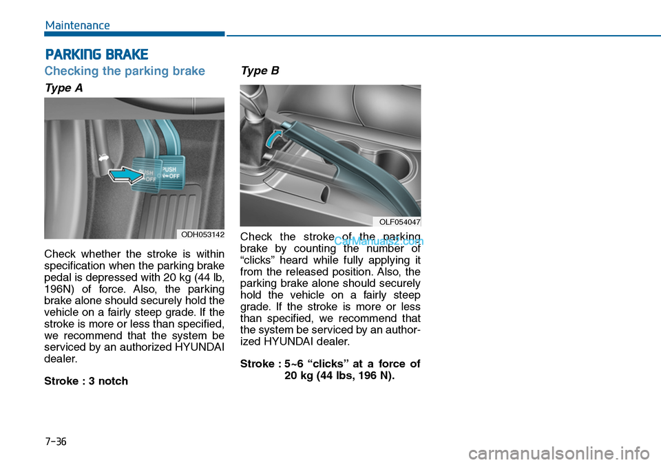
Checking the parking brake
Type A
Check whether the stroke is within
specification when the parking brake
pedal is depressed with 20 kg (44 lb,
196N) of force. Also, the parking
brake alone should securely hold the
vehicle on a fairly steep grade. If the
stroke is more or less than specified,
we recommend that the system be
serviced by an authorized HYUNDAI
dealer.
Stroke : 3 notch
Type B
Check the stroke of the parking
brake by counting the number of
“clicks’’ heard while fully applying it
from the released position. Also, the
parking brake alone should securely
hold the vehicle on a fairly steep
grade. If the stroke is more or less
than specified, we recommend that
the system be serviced by an author-
ized HYUNDAI dealer.
Stroke : 5~6 “clicks’’ at a force of
20 kg (44 lbs, 196 N).
ODH053142
OLF054047
Page 599 of 665
7-42
Maintenance
BATTERY
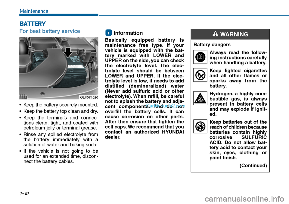
For best battery service
•Keep the battery securely mounted.
•Keep the battery top clean and dry.
•Keep the terminals and connec-
tions clean, tight, and coated with
petroleum jelly or terminal grease.
•Rinse any spilled electrolyte from
the battery immediately with a
solution of water and baking soda.
•If the vehicle is not going to be
used for an extended time, discon-
nect the battery cables.
Information
Basically equipped battery is
maintenance free type. If your
vehicle is equipped with the bat-
tery marked with LOWER and
UPPER on the side, you can check
the electrolyte level. The elec-
trolyte level should be between
LOWER and UPPER. If the elec-
trolyte level is low, it needs to add
distilled (demineralized) water
(Never add sulfuric acid or other
electrolyte). When refill, be careful
not to splash the battery and adja-
cent components. And do not
overfill the battery cells. It can
cause corrosion on other parts.
After then ensure that tighten the
cell caps. We recommend that you
contact an authorized HYUNDAI
dealer.
i
Battery dangers
Always read the follow-
ing instructions carefully
when handling a battery.
Keep lighted cigarettes
and all other flames or
sparks away from the
battery.
Hydrogen, a highly com-
bustible gas, is always
present in battery cells
and may explode if ignit-
ed.
Keep batteries out of the
reach of children because
batteries contain highly
corrosive SULFURIC
ACID. Do not allow bat-
tery acid to contact your
skin, eyes, clothing or
paint finish.
(Continued)
WARNING
OLF074020
Page 611 of 665
7-54
Maintenance
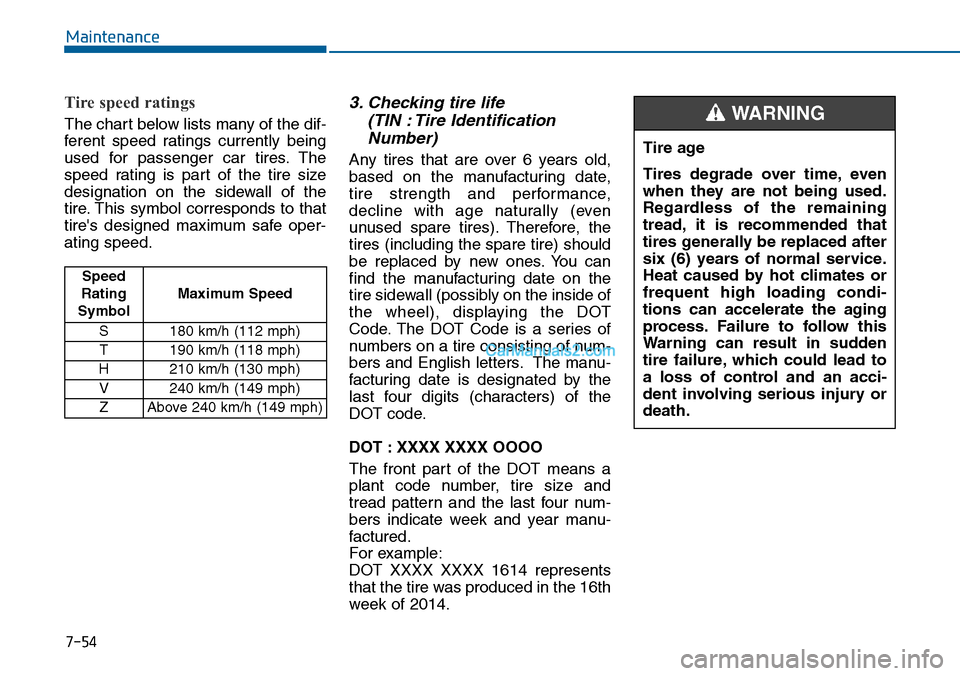
Tire speed ratings
The chart below lists many of the dif-
ferent speed ratings currently being
used for passenger car tires. The
speed rating is part of the tire size
designation on the sidewall of the
tire. This symbol corresponds to that
tire's designed maximum safe oper-
ating speed.
3. Checking tire life
(TIN : Tire Identification
Number)
Any tires that are over 6 years old,
based on the manufacturing date,
tire strength and performance,
decline with age naturally (even
unused spare tires). Therefore, the
tires (including the spare tire) should
be replaced by new ones. You can
find the manufacturing date on the
tire sidewall (possibly on the inside of
the wheel), displaying the DOT
Code. The DOT Code is a series of
numbers on a tire consisting of num-
bers and English letters. The manu-
facturing date is designated by the
last four digits (characters) of the
DOT code.
DOT : XXXX XXXX OOOO
The front part of the DOT means a
plant code number, tire size and
tread pattern and the last four num-
bers indicate week and year manu-
factured.
For example:
DOT XXXX XXXX 1614 represents
that the tire was produced in the 16th
week of 2014.
Tire age
Tires degrade over time, even
when they are not being used.
Regardless of the remaining
tread, it is recommended that
tires generally be replaced after
six (6) years of normal service.
Heat caused by hot climates or
frequent high loading condi-
tions can accelerate the aging
process. Failure to follow this
Warning can result in sudden
tire failure, which could lead to
a loss of control and an acci-
dent involving serious injury or
death.
WARNING
Speed
Rating
Symbol
Maximum Speed
S 180 km/h (112 mph)
T190 km/h (118 mph)
H210 km/h (130 mph)
V 240 km/h (149 mph)
ZAbove 240 km/h (149 mph)
Page 612 of 665
7-55
7
Maintenance
4. Tire ply composition and
material
The number of layers or plies of rub-
ber-coated fabric are in the tire. Tire
manufacturers also must indicate the
materials in the tire, which include
steel, nylon, polyester, and others.
The letter "R" means radial ply con-
struction; the letter "D" means diago-
nal or bias ply construction; and the
letter "B" means belted-bias ply con-
struction.
5. Maximum permissible infla-
tion pressure
This number is the greatest amountof air pressure that should be put inthe tire. Do not exceed the maximumpermissible inflation pressure. Referto the Tire and Loading Informationlabel for recommended inflationpressure.
6. Maximum load rating
This number indicates the maximum
load in kilograms and pounds that
can be carried by the tire. When
replacing the tires on the vehicle,
always use a tire that has the same
load rating as the factory installed
tire.
7. Uniform tire quality grading
Quality grades can be found where
applicable on the tire sidewall
between tread shoulder and maxi-
mum section width.
For example:
TREADWEAR 200
TRACTION AA
TEMPERATURE A
Tr e a d w e a r
The tread wear grade is a compara-
tive rating based on the wear rate of
the tire when tested under controlled
conditions on a specified govern-
ment test course. For example, a tire
graded 150 would wear one-and-a-
half times (1½) as well on the gov-
ernment course as a tire graded 100.
The relative performance of tires
depends upon the actual conditions
of their use, however, and may
depart significantly from the norm
because of variations in driving
habits, service practices and differ-
ences in road characteristics and cli-
mate.
These grades are molded on the
side-walls of passenger vehicle tires.
The tires available as standard or
optional equipment on your vehicles
may vary with respect to grade.
Page 638 of 665
7-81
7
Maintenance
Rear combination light bulb
replacement
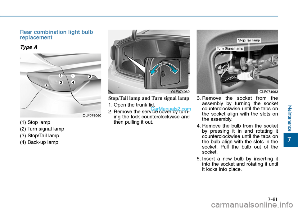
Type A
(1) Stop lamp
(2) Turn signal lamp
(3) Stop/Tail lamp
(4) Back-up lamp
Stop/Tail lamp and Turn signal lamp
1. Open the trunk lid.
2. Remove the service cover by turn-
ing the lock counterclockwise and
then pulling it out.
3. Remove the socket from the
assembly by turning the socket
counterclockwise until the tabs on
the socket align with the slots on
the assembly.
4. Remove the bulb from the socket
by pressing it in and rotating it
counterclockwise until the tabs on
the bulb align with the slots in the
socket. Pull the bulb out of the
socket.
5. Insert a new bulb by inserting it
into the socket and rotating it until
it locks into place.
OLF074063OLF074062
Stop/Tail lamp
Turn Signal lamp
OLF074060
Page 640 of 665
7-83
7
Maintenance
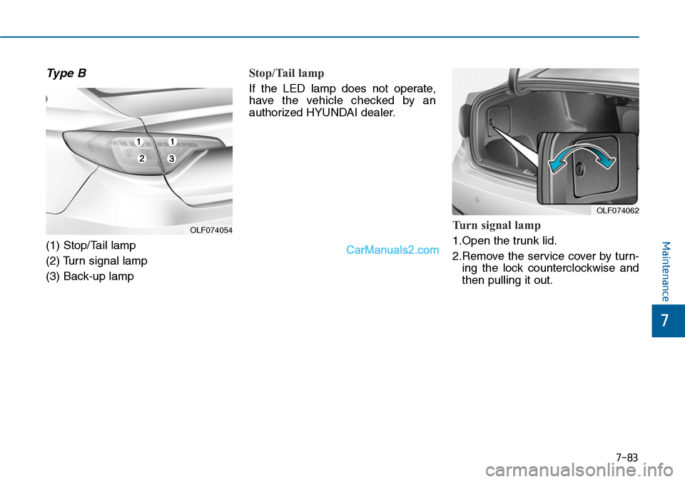
Type B
(1) Stop/Tail lamp
(2) Turn signal lamp
(3) Back-up lamp
Stop/Tail lamp
If the LED lamp does not operate,
have the vehicle checked by an
authorized HYUNDAI dealer.
Turn signal lamp
1.Open the trunk lid.
2.Remove the service cover by turn-
ing the lock counterclockwise and
then pulling it out.
OLF074054
OLF074062
Page 652 of 665
7-95
7
Maintenance
EMISSION CONTROL SYSTEM
The emission control system of your
vehicle is covered by a written limited
warranty. Please see the warranty
information contained in the Service
Passpor t in your vehicle.
Yo u r v e h i c l e i s e q u i p p e d w i t h a n
emission control system to meet all
emission regulations.
There are three emission control
systems which are as follows.
(1) Crankcase emission control sys-
tem
(2) Evaporative emission control sys-
tem
(3) Exhaust emission control system
In order to assure the proper function
of the emission control systems, it is
recommended that you have your
car inspected and maintained by an
authorized HYUNDAI dealer in
accordance with the maintenance
schedule in this manual.
1. Crankcase emission control
system
The positive crankcase ventilation
system is employed to prevent air
pollution caused by blow-by gases
being emitted from the crankcase.
This system supplies fresh filtered air
to the crankcase through the air
intake hose. Inside the crankcase,
the fresh air mixes with blow-by
gases, which then pass through the
PCV valve into the induction system.
2. Evaporative emission con-
trol system
The Evaporative Emission Control
System is designed to prevent fuel
vapors from escaping into the atmos-
phere.
For the Inspection and
Maintenance Test (With Electronic
Stability Control (ESC) system)
•To prevent the vehicle from
misfiring during dynamome-
ter testing, turn the Electronic
Stability Control (ESC) sys-
tem off by pressing the ESC
switch.
•After dynamometer testing is
completed, turn the ESC sys-
tem back on by pressing the
ESC switch again.
CAUTION