Page 309 of 476

537
Driving your vehicle
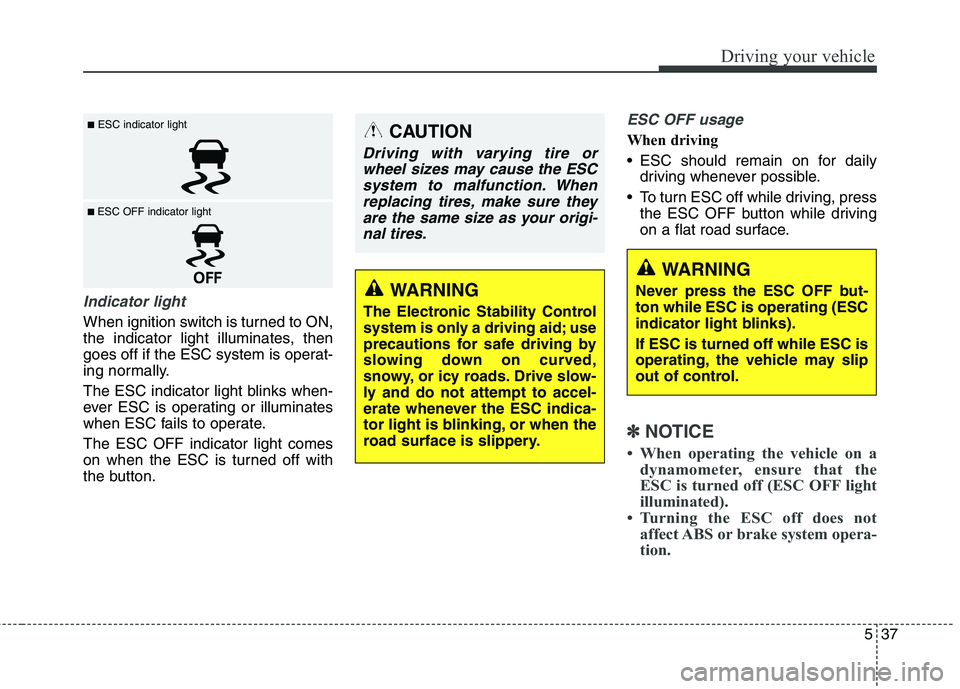
Indicator light
When ignition switch is turned to ON,
the indicator light illuminates, then
goes off if the ESC system is operat-
ing normally.
The ESC indicator light blinks when-
ever ESC is operating or illuminates
when ESC fails to operate.
The ESC OFF indicator light comes
on when the ESC is turned off with
the button.
ESC OFF usage
When driving
ESC should remain on for daily
driving whenever possible.
To turn ESC off while driving, press
the ESC OFF button while driving
on a flat road surface.
✽ ✽
NOTICE
• When operating the vehicle on a
dynamometer, ensure that the
ESC is turned off (ESC OFF light
illuminated).
• Turning the ESC off does not
affect ABS or brake system opera-
tion.
■ESC indicator light
■ ESC OFF indicator light
CAUTION
Driving with varying tire or
wheel sizes may cause the ESC
system to malfunction. When
replacing tires, make sure they
are the same size as your origi-
nal tires.
WARNING
The Electronic Stability Control
system is only a driving aid; use
precautions for safe driving by
slowing down on curved,
snowy, or icy roads. Drive slow-
ly and do not attempt to accel-
erate whenever the ESC indica-
tor light is blinking, or when the
road surface is slippery.
WARNING
Never press the ESC OFF but-
ton while ESC is operating (ESC
indicator light blinks).
If ESC is turned off while ESC is
operating, the vehicle may slip
out of control.
Page 321 of 476

549
Driving your vehicle
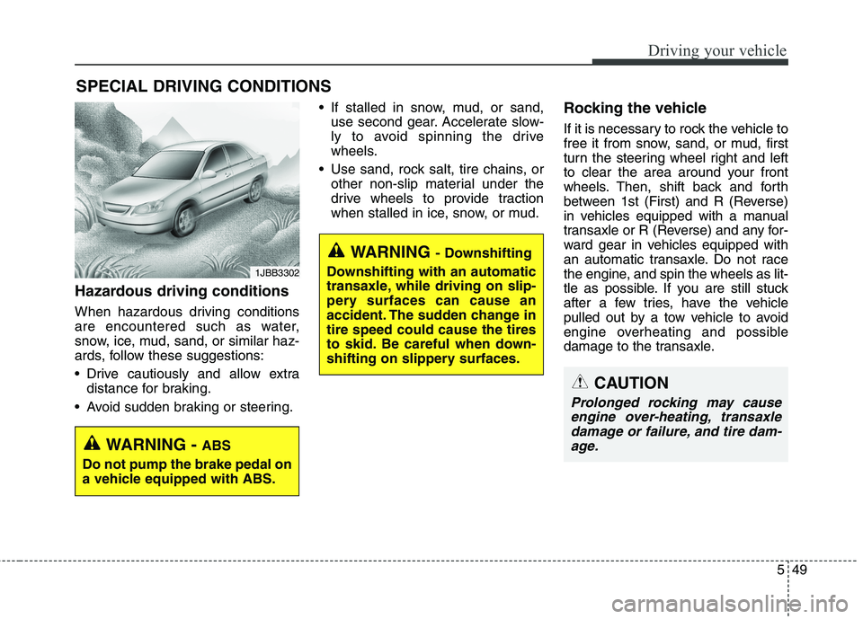
Hazardous driving conditions
When hazardous driving conditions
are encountered such as water,
snow, ice, mud, sand, or similar haz-
ards, follow these suggestions:
Drive cautiously and allow extra
distance for braking.
Avoid sudden braking or steering. If stalled in snow, mud, or sand,
use second gear. Accelerate slow-
ly to avoid spinning the drive
wheels.
Use sand, rock salt, tire chains, or
other non-slip material under the
drive wheels to provide traction
when stalled in ice, snow, or mud.
Rocking the vehicle
If it is necessary to rock the vehicle to
free it from snow, sand, or mud, first
turn the steering wheel right and left
to clear the area around your front
wheels. Then, shift back and forth
between 1st (First) and R (Reverse)
in vehicles equipped with a manual
transaxle or R (Reverse) and any for-
ward gear in vehicles equipped with
an automatic transaxle. Do not race
the engine, and spin the wheels as lit-
tle as possible. If you are still stuck
after a few tries, have the vehicle
pulled out by a tow vehicle to avoid
engine overheating and possible
damage to the transaxle.
SPECIAL DRIVING CONDITIONS
1JBB3302
WARNING - ABS
Do not pump the brake pedal on
a vehicle equipped with ABS.
WARNING - Downshifting
Downshifting with an automatic
transaxle, while driving on slip-
pery surfaces can cause an
accident. The sudden change in
tire speed could cause the tires
to skid. Be careful when down-
shifting on slippery surfaces.
CAUTION
Prolonged rocking may cause
engine over-heating, transaxle
damage or failure, and tire dam-
age.
Page 409 of 476

Maintenance
48 7
Tire replacement
If the tire is worn evenly, a tread wear
indicator will appear as a solid band
across the tread. This shows there is
less than 1/16 inch (1.6 mm) of tread
left on the tire. Replace the tire when
this happens.
Do not wait for the band to appear
across the entire tread before replac-
ing the tire.
OEN076053
Tread wear indicatorWARNING - Replacing
tires
To reduce the chance or serious
or fatal injuries from an acci-
dent caused by tire failure or
loss of vehicle control:
Replace tires that are worn,
show uneven wear, or are
damaged. Worn tires can
cause loss of braking effec-
tiveness, steering control, and
traction.
Do not drive your vehicle with
too little or too much pressure
in your tires. This can lead to
uneven wear and tire failure.
When replacing tires, never
mix radial and bias-ply tires
on the same car. You must
replace all tires if moving from
radial to bias-ply tires.
(Continued)(Continued)
Using tires and wheels other
than the recommended sizes
could cause unusual handling
characteristics and poor vehi-
cle control, resulting in a seri-
ous accident.
Wheels that do not meet
HYUNDAI’s specifications may
fit poorly and result in damage
to the vehicle or unusual han-
dling and poor vehicle control.
The ABS works by comparing
the speed of the wheels. Tire
size can affect wheel speed.
When replacing tires, all 4
tires must use the same size
originally supplied with the
vehicle. Using tires of a differ-
ent size can cause the ABS
(Anti-lock Brake System) and
ESC (Electronic Stability
Control) to work irregularly.
Page 428 of 476
767
Maintenance
DescriptionFuse ratingProtected component
MULTI
FUSE
MDPS80AEPS Control Module
B+160AI/P Junction Box (IPS 0 (4CH), IPS 1 (4CH), IPS 2 (2CH),
Fuse - F13/F14/F19/F20/F21/F26/ F36)
ABS 160AESC Control Module, Multipurpose Check Connector
BLOWER40ARLY. 4 (Blower Relay)
B+260AI/P Junction Box (IPS 3 (4CH), IPS 4 (4CH), Fuse - F2/F7/F9/F15)
GSL
PTC60ARLY. 12 (GASOLINE PTC Relay)
FUSE
C/FAN40ARLY. 1 (C/FAN LO Relay), RLY. 2 (C/FAN HI Relay)
ABS 220AESC Control Module, Multipurpose Check Connector
IG240ARLY. 9 (Start Relay), Ignition Switch (W/O Button Start),
RLY. 6 (PDM 4 (IG2) Relay, With Button Start)
IG140AW/O Button Start : Ignition Switch,
With Button Start : RLY. 8 (PDM 2 (ACC) Relay)/RLY. 10 (PDM 3 (IG1) Relay
DEICER15AICM Relay Box (Front Deicer Relay)
B+350AI/P Junction Box (Leak Current Autocut Device, Fuse - F18/F25/F30/F34/F38)
BRAKE SWITCH10ASmart Key Control Module, Stop Signal Relay
Page 429 of 476
Maintenance
68 7
DescriptionFuse ratingProtected component
FUSE
EPB 130AElectric Parking Brake Module
EPB 230AElectric Parking Brake Module
TCU 220AD4FD & A/T : TCM
S/HEATER
FRT20ADriver/Passenger Seat Warmer Module
WIPER10APCM/ECM
HORN15ARLY. 5 (Horn Relay), ICM Relay Box (B/A Horn Relay)
TCU 115AA/T - TCM (D4FD), Transaxle Range Switch
ECU 615ARLY. 9 (D4FD, Start Relay), ECM/PCM
ABS 310AESC Control Module, Multipurpose Check Connector
ECU 310AECM/PCM, Air Flow Sensor, Stop Lamp Switch
B/UP
LAMP10AM/T - Back-Up Lamp Switch, A/T - Rear Combination Lamp (IN) LH/RH,
Rear Curtain Module, Navigation Head Unit, Electro Chromic Mirror, IPS Control Module
Page 435 of 476

Maintenance
74 7
12. Connect the headlight bulb sock-
et-connector.
13. Install the headlight bulb cover by
turning it clockwise.Headlight (Low)
Follow the steps 1 to 6 from the pre-
vious page.
7. Remove the cover by turning it
counterclockwise.
8. Remove the socket from the
assembly by turning the socket
counterclockwise until the tabs on
the socket align with the slots on
the assembly.
9. Pull the bulb out of the socket.
10. Insert a new bulb into the socket.
11. Install the socket in the assembly
by aligning the tabs on the sock-
et with the slots in the assembly.
Push the socket into the assem-
bly and turn the socket clockwise.
12. Install the headlight bulb cover by
turning it clockwise.
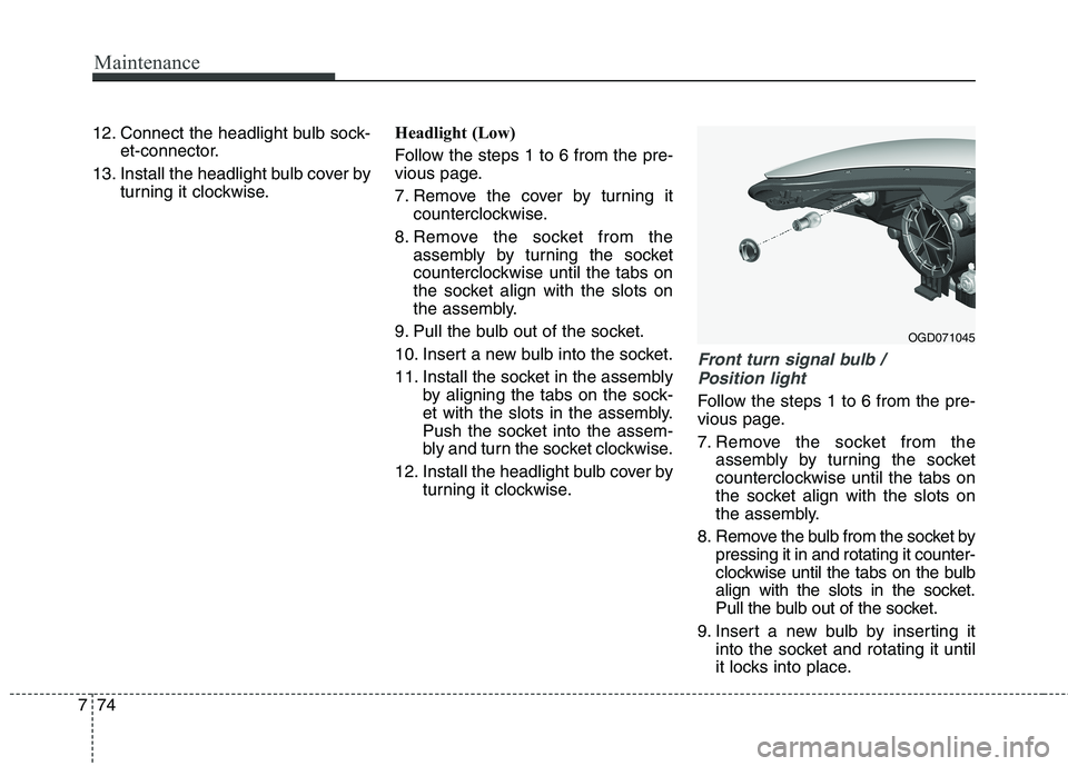
Front turn signal bulb /
Position light
Follow the steps 1 to 6 from the pre-
vious page.
7. Remove the socket from the
assembly by turning the socket
counterclockwise until the tabs on
the socket align with the slots on
the assembly.
8. Remove the bulb from the socket by
pressing it in and rotating it counter-
clockwise until the tabs on the bulb
align with the slots in the socket.
Pull the bulb out of the socket.
9. Insert a new bulb by inserting it
into the socket and rotating it until
it locks into place.
OGD071045
Page 436 of 476
775
Maintenance
10. Install the socket in the assembly
by aligning the tabs on the sock-
et with the slots in the assembly.
Push the socket into the assem-
bly and turn the socket clockwise.
11. Reinstall the light assembly to
the body of the vehicle.
Front side marker
Follow the steps 1 to 6 from the pre-
vious page.
7. Remove the socket from the
assembly by turning the socket
counterclockwise until the tabs on
the socket align with the slots on
the assembly.
8. Remove the bulb from the socket
by pulling out the bulb.
9. Insert a new bulb.10. Install the socket in the assembly
by aligning the tabs on the sock-
et with the slots in the assembly.
Push the socket into the assem-
bly and turn the socket clockwise.
11. Reinstall the light assembly to
the body of the vehicle.
OGD072062N
Page 437 of 476
Maintenance
76 7
Front fog light (if equipped)
Follow the steps 1 to 6 from the pre-
vious page.
7. Disconnect the power connector
from the socket.
8. Remove the bulb-socket from the
housing by turning the socket
counter clockwise until the tabs on
the socket align with the slots on
the housing.
9. Install the new bulb-socket into the
housing by aligning the tabs on the
socket with the slots in the hous-
ing. Push the socket into the hous-
ing and turn the socket clockwise.
10. Connect the power connector to
the socket.
Side repeater light bulb
replacement (if equipped)
If the light bulb is not operating, we
recommend that the vehicle be
checked by an authorized HYUNDAI
dealer.
Rear combination light bulb
replacement
(1) Back-up light
(2) Tail light
(3) Rear turn signal light
(4) Stop/tail light
(5) Side marker
OGDE071055LOGD071031OGD071030