2014 FORD SUPER DUTY parking brake
[x] Cancel search: parking brakePage 169 of 458
PRINCIPLE OF OPERATION
WARNINGS
Hill descent control cannot control
descent in all surface conditions and
circumstances, such as ice or
extremely steep grades. Hill descent
control is a driver assist system and cannot
substitute for good judgment by the driver.
Failure to do so may result in loss of vehicle
control, crash or serious injury. Hill descent control does not provide
hill hold at zero miles per hour (0
kilometers per hour). When stopped,
the parking brake must be applied or the
vehicle must be placed in P (Park) or it
may roll away. Hill descent control allows the driver to set
and maintain vehicle speed while
descending steep grades in various surface
conditions.
Hill descent control can maintain vehicle
speeds on downhill grades between 2 mph
(3 km/h) and 12 mph (20 km/h). Above 20
mph (32 km/h), the system remains
armed, but descent speed cannot be set
or maintained.
Hill descent control requires a cooling
down interval after a period of sustained
use. The amount of time that the feature
can remain active before cooling varies
with conditions. The system will provide a
warning in the message center and a chime
will sound when the system is about to
disengage for cooling. At this time,
manually apply the brakes as needed to
maintain descent speed. USING HILL DESCENT
CONTROL Press and release the hill
descent button located on the
instrument panel. A light in the
cluster will illuminate and a
chime will sound when this feature is
activated.
To increase descent speed, press the
accelerator pedal until the desired speed
is reached. To decrease descent speed,
press the brake pedal until the desired
speed is reached.
Whether accelerating or decelerating, once
the desired descent speed is reached,
remove your feet from the pedals and the
chosen vehicle speed will be maintained.
Note: Noise from the ABS pump motor may
be observed during hill descent control
operation. This is a normal characteristic of
the ABS and should be no reason for
concern.
Hill descent modes
• At speeds below 20 mph (32 km/h):
When the Hill Descent Control switch
is pressed and Hill Descent Control is
active, the Hill Descent Control telltale
will flash.
• At speeds below 20 mph (32 km/h):
When the Hill Descent Control switch
is pressed and conditions are not
correct for hill descent activation, the
Hill Descent Control system will be
enabled, the Hill Descent Control
telltale will be solid and a message will
display in the information display.
166
Super Duty (TFA) Terrain ResponseE163957
Page 171 of 458

PARKING AID (IF EQUIPPED)
WARNINGS
To help avoid personal injury, please
read and understand the limitations
of the system as contained in this
section. Sensing is only an aid for some
(generally large and fixed) objects when
moving in reverse on a flat surface at
parking speeds. Traffic control systems,
inclement weather, air brakes, and external
motors and fans may also affect the
function of the sensing system; this may
include reduced performance or a false
activation. To help avoid personal injury, always
use caution when in R (Reverse) and
when using the sensing system.
This system is not designed to
prevent contact with small or moving
objects. The system is designed to
provide a warning to assist the driver in
detecting large stationary objects to avoid
damaging the vehicle. The system may not
detect smaller objects, particularly those
close to the ground. Certain add-on devices such as large
trailer hitches, bike or surfboard racks
and any device that may block the
normal detection zone of the system, may
create false beeps. Note:
Keep the sensors, located on the
bumper or fascia, free from snow, ice and
large accumulations of dirt. If the sensors
are covered, the system ’s accuracy can be
affected. Do not clean the sensors with
sharp objects.
Note: If your vehicle sustains damage to
the bumper or fascia, leaving it misaligned
or bent, the sensing zone may be altered
causing inaccurate measurement of
obstacles or false alarms. Note:
If your vehicle is equipped with
MyKey ™, it is possible to prevent turning
the sensing system off. See MyKey ™
(page
49).
Note: If your vehicle is equipped with a fully
integrated electronic trailer brake controller
(TBC) and a trailer with electric trailer
brakes is connected to your vehicle, the RSS
will be disabled. When the vehicle is shifted
into reverse, the information display will
remain in the Rear Park Aid Off selection.
For more information on the TBC, See
Trailer Sway Control
(page 186).
The sensing system warns the driver of
obstacles within a certain range of the
bumper area. The system turns on
automatically whenever the ignition is
switched on.
When receiving a detection warning, the
radio volume is reduced to a
predetermined level. After the warning
goes away, the radio volume returns to the
previous level.
Rear Sensing System
The rear sensors are only active when the
transmission is in R (Reverse). As the
vehicle moves closer to the obstacle, the
rate of the audible warning increases.
When the obstacle is fewer than 12 inches
(30 centimeters) away, the warning
sounds continuously. If a stationary or
receding object is detected farther than 12
inches (30 centimeters) from the side of
the vehicle, the tone sounds for only three
seconds. Once the system detects an
object approaching, the warning sounds
again.
168
Super Duty (TFA) Parking Aids
Page 192 of 458
Once the trailer is level or slightly nose
down toward the vehicle:
•
Lock the bar tension adjuster in place.
• Check that the trailer tongue securely
attaches and locks onto the hitch.
• Install safety chains, lighting, and trailer
brake controls as required by law or the
trailer manufacturer.
Fifth-wheel Trailer Hitch (If Equipped) WARNINGS
The mounting pads in the bed are
specifically designed for certain
fifth-wheel trailer hitches and
gooseneck ball hitches. Do not use these
mounting pads for other purposes. Doing
so could result in vehicle structural
damage, loss of vehicle control, and
personal injury. Contact an authorized
dealer to purchase gooseneck and
fifth-wheel hitches that are compatible
with your vehicle. Towing trailers beyond the maximum
limit of the towing system could
result in vehicle structural damage,
loss of vehicle control and personal injury. The hitch rating listed on the trailer
hitch label is the maximum possible
trailer rating. To find the maximum
trailer weight allowed for your specific
vehicle, consult an authorized dealer or the
RV & Trailer Towing Guide provided by an
authorized dealer. Your vehicle may be equipped with a
fifth-wheel prep package. This package
enables your vehicle to accept certain
fifth-wheel trailer hitches and gooseneck
ball hitches. The fifth-wheel trailer hitch
attaches to the four mounting pads in the
pick-up bed. An optional 7-pin trailer wiring
connector may be in the bed as well. The
gooseneck ball hitch is a separate
mounting pad from the fifth-wheel hitch,
located in the center of the bed. Shorter pick-up boxes, such as the 6½-foot
box on the F-250 and F-350, provide less
clearance between the cab and the
fifth-wheel and gooseneck trailer
compared to longer box pick-ups, such as
an 8-foot box on the F-250 or F-350. When
selecting a trailer and tow vehicle, it is
critical to check that this combination
provides clearance between the front of
the trailer and tow vehicle for turns up to
90 degrees. Failure to follow this
recommendation could result in the trailer
contacting the cab of the tow vehicle
during tight turns that are typical during
low-speed parking and turning maneuvers.
This contact could result in damage to the
trailer and tow vehicle.
Safety Chains
Note:
Do not attach safety chains to the
bumper.
Always connect the safety chains to the
frame or hook retainers of your vehicle
hitch.
To connect the safety chains, cross the
chains under the trailer tongue and allow
enough slack for turning tight corners. Do
not allow the chains to drag on the ground.
Trailer Brakes WARNING
Do not connect a trailer's hydraulic
brake system directly to your
vehicle's brake system. Your vehicle
may not have enough braking power and
your chances of having a collision greatly
increase. Electric brakes and manual, automatic or
surge-type trailer brakes are safe if you
install them properly and adjust them to
the manufacturer's specifications. The
trailer brakes must meet local and federal
regulations.
189
Super Duty (TFA) Towing
Page 197 of 458
•
Allow more distance for stopping with
a trailer attached. Anticipate stops and
brake gradually.
• Avoid parking on a grade. However, if
you must park on a grade:
•Turn the steering wheel to point
your vehicle tires away from traffic
flow.
• Set your vehicle parking brake.
• Place the automatic transmission
in position P.
• Place wheel chocks in front and
back of the trailer wheels. (Chocks
not included with vehicle.)
Your vehicle may be equipped with a
temporary or conventional spare tire. A
"temporary" spare tire is different in size
(diameter or width), tread-type
(All-Season or All Terrain) or is from a
different manufacturer than the road tires
on your vehicle. Consult information on the
tire label or Safety Compliance label for
limitations when using.
Launching or Retrieving a Boat or
Personal Watercraft (PWC)
Note: Disconnect the wiring to the trailer
before
backing the trailer into the water.
Note: Reconnect the wiring to the trailer
after
the trailer is removed from the water.
When backing down a ramp during boat
launching or retrieval:
• Do not allow the static water level to
rise above the bottom edge of the rear
bumper.
• Do not allow waves to break higher
than 6 inches (15 centimeters) above
the bottom edge of the rear bumper. Exceeding these limits may allow water to
enter vehicle components:
•
Causing internal damage to the
components.
• Affecting driveability, emissions, and
reliability.
Replace the rear axle lubricant anytime
the rear axle has been submerged in water.
Water may have contaminated the rear
axle lubricant, which is not normally
checked or changed unless a leak is
suspected or other axle repair is required.
TOWING POINTS WARNINGS
Using recovery hooks is dangerous
and should only be done by a person
familiar with proper vehicle recovery
safety practices. Improper use of recovery
hooks may cause hook failure or separation
from the vehicle and could result in serious
injury or death. Always slowly remove the slack from
the recovery strap prior to pulling.
Failure to do so can introduce
significantly higher loads which can cause
the recovery hooks to break off, or the
recovery strap to fail which can cause
serious injury or death. Never link two straps together with
a clevis pin. These heavy metal
objects could become projectiles if
the strap breaks and can cause serious
injury or death. Your vehicle comes equipped with
frame-mounted front recovery hooks.
These hooks should never have a load
applied to them greater than the gross
vehicle weight rating of your vehicle.
194
Super Duty (TFA) Towing
Page 224 of 458
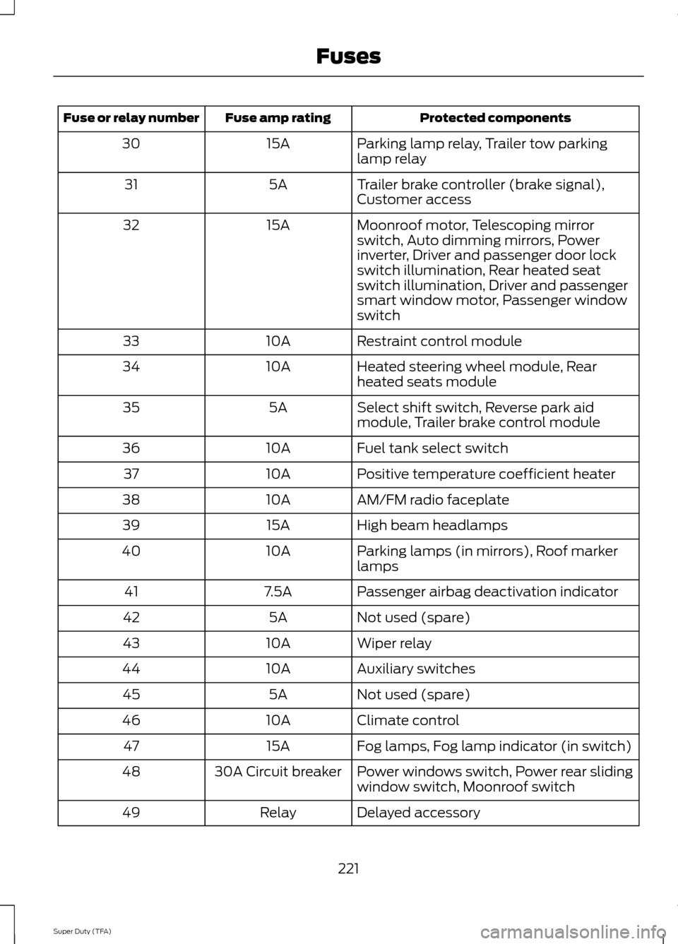
Protected components
Fuse amp rating
Fuse or relay number
Parking lamp relay, Trailer tow parking
lamp relay
15A
30
Trailer brake controller (brake signal),
Customer access
5A
31
Moonroof motor, Telescoping mirror
switch, Auto dimming mirrors, Power
inverter, Driver and passenger door lock
switch illumination, Rear heated seat
switch illumination, Driver and passenger
smart window motor, Passenger window
switch
15A
32
Restraint control module
10A
33
Heated steering wheel module, Rear
heated seats module
10A
34
Select shift switch, Reverse park aid
module, Trailer brake control module
5A
35
Fuel tank select switch
10A
36
Positive temperature coefficient heater
10A
37
AM/FM radio faceplate
10A
38
High beam headlamps
15A
39
Parking lamps (in mirrors), Roof marker
lamps
10A
40
Passenger airbag deactivation indicator
7.5A
41
Not used (spare)
5A
42
Wiper relay
10A
43
Auxiliary switches
10A
44
Not used (spare)
5A
45
Climate control
10A
46
Fog lamps, Fog lamp indicator (in switch)
15A
47
Power windows switch, Power rear sliding
window switch, Moonroof switch
30A Circuit breaker
48
Delayed accessory
Relay
49
221
Super Duty (TFA) Fuses
Page 225 of 458
GENERAL INFORMATION
Have your vehicle serviced regularly to help
maintain its roadworthiness and resale
value. There is a large network of Ford
authorized dealers that are there to help
you with their professional servicing
expertise. We believe that their specially
trained technicians are best qualified to
service your vehicle properly and expertly.
They are supported by a wide range of
highly specialized tools developed
specifically for servicing your vehicle.
To help you service your vehicle, we
provide scheduled maintenance
information which makes tracking routine
service easy. See Scheduled
Maintenance (page 428).
If your vehicle requires professional service,
your authorized dealer can provide the
necessary parts and service. Check your
warranty information to find out which
parts and services are covered.
Use only recommended fuels, lubricants,
fluids and service parts conforming to
specifications. Motorcraft® parts are
designed and built to provide the best
performance in your vehicle.
Precautions
• Do not work on a hot engine.
• Make sure that nothing gets caught in
moving parts.
• Do not work on a vehicle with the
engine running in an enclosed space,
unless you are sure you have enough
ventilation.
• Keep all open flames and other burning
material (such as cigarettes) away
from the battery and all fuel related
parts. Working with the Engine Off
1. Set the parking brake and shift to
P
(Park).
2. Turn off the engine and remove the key
(if equipped).
3. Block the wheels.
Working with the Engine On WARNING
To reduce the risk of vehicle damage
and/or personal burn injuries, do not
start your engine with the air cleaner
removed and do not remove it while the
engine is running. 1. Set the parking brake and shift to
P
(Park).
2. Block the wheels
OPENING AND CLOSING THE
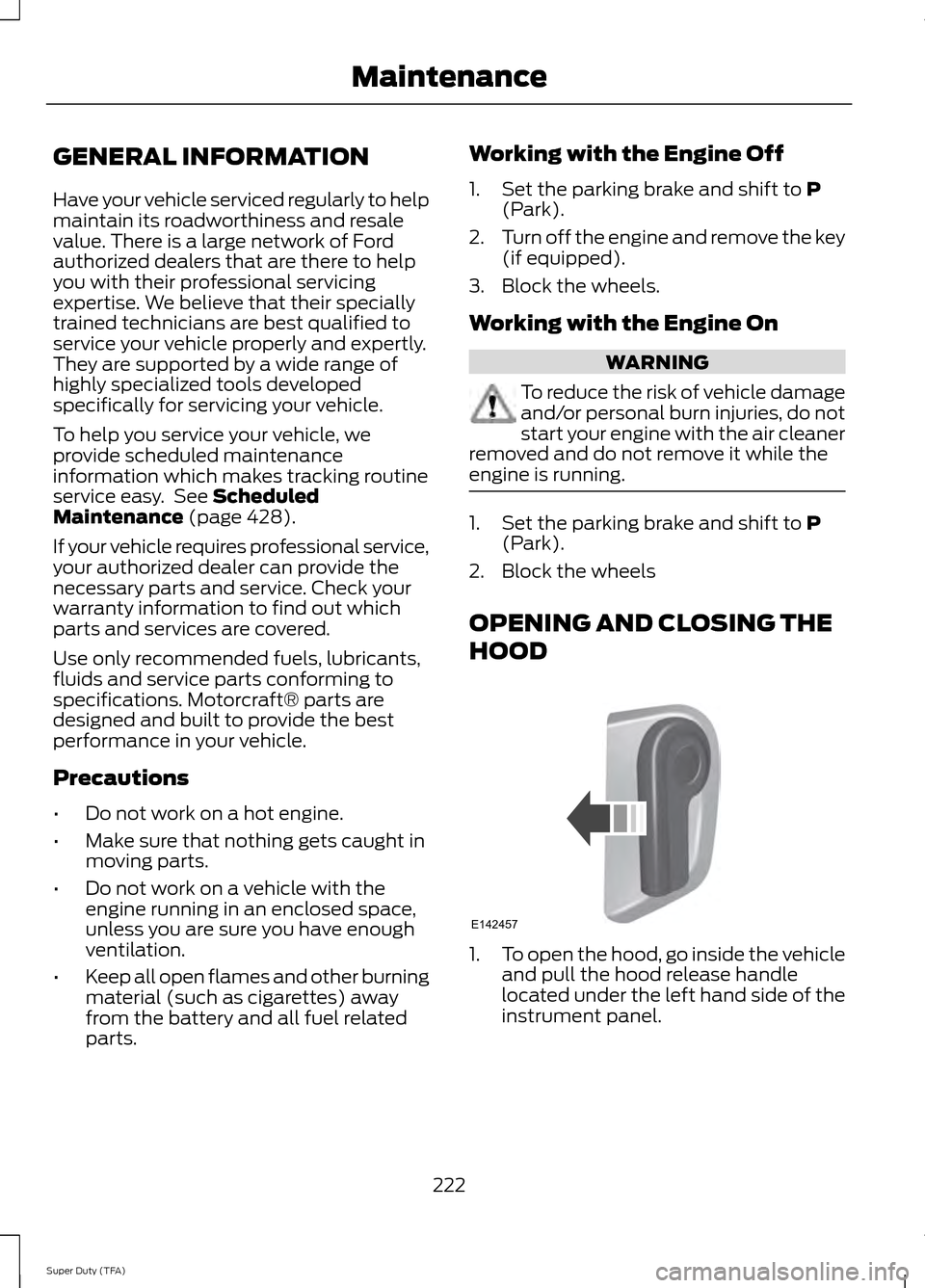
HOOD 1.
To open the hood, go inside the vehicle
and pull the hood release handle
located under the left hand side of the
instrument panel.
222
Super Duty (TFA) MaintenanceE142457
Page 228 of 458
Power steering fluid reservoir
F.
Brake fluid reservoir
G.
Engine coolant reservoir
H.
Air filter assembly
I.
Power distribution box
J.
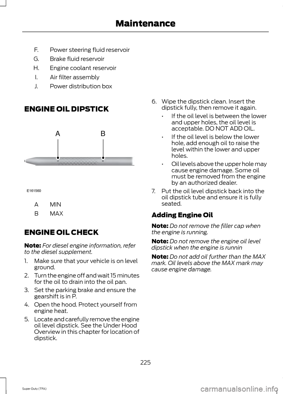
ENGINE OIL DIPSTICK MINA
MAX
B
ENGINE OIL CHECK
Note: For diesel engine information, refer
to the diesel supplement.
1. Make sure that your vehicle is on level ground.
2. Turn the engine off and wait 15 minutes
for the oil to drain into the oil pan.
3. Set the parking brake and ensure the gearshift is in P.
4. Open the hood. Protect yourself from engine heat.
5. Locate and carefully remove the engine
oil level dipstick. See the Under Hood
Overview in this chapter for location of
dipstick. 6. Wipe the dipstick clean. Insert the
dipstick fully, then remove it again.
•If the oil level is between the lower
and upper holes, the oil level is
acceptable. DO NOT ADD OIL.
• If the oil level is below the lower
hole, add enough oil to raise the
level within the lower and upper
holes.
• Oil levels above the upper hole may
cause engine damage. Some oil
must be removed from the engine
by an authorized dealer.
7. Put the oil level dipstick back into the oil dipstick tube and ensure it is fully
seated.
Adding Engine Oil
Note: Do not remove the filler cap when
the engine is running.
Note: Do not remove the engine oil level
dipstick when the engine is runnin
Note: Do not add oil further than the MAX
mark. Oil levels above the MAX mark may
cause engine damage.
225
Super Duty (TFA) MaintenanceE161560
AB
Page 233 of 458
•
the engine coolant temperature gauge
moves fully into the red (hot) area
• the coolant temperature warning light
illuminates
• the service engine soon indicator
illuminates. WARNING
Never remove the coolant reservoir
cap while the engine is running or hot.
1. Pull off the road as soon as safely
possible and place the vehicle in P
(Park).
2. Leave the engine running until the coolant temperature gauge needle
moves away from the H range. After
several minutes, if this does not
happen, follow the remaining steps.
3. Turn the engine off and wait for it to cool before checking the coolant level.
4. If the coolant level is normal, you may restart your engine and continue on.
5. If the coolant is low, add coolant, restart the engine and take your vehicle
to an authorized dealer. See Adding
engine coolant in this chapter for more
information. Refer to fail-safe cooling
for additional information.
AUTOMATIC TRANSMISSION
FLUID CHECK
Have an authorized dealer check and
change the transmission fluid and filter at
the correct service interval. See
Scheduled Maintenance (page 428).
Do not use supplemental transmission
fluid additives, treatments or cleaning
agents. The use of these materials may
affect transmission operation and result
in damage to internal transmission
components. Checking Automatic Transmission
Fluid (If Equipped)
For scheduled intervals of the fluid checks
and changes, See
Scheduled
Maintenance (page 428). Your
transmission does not consume fluid.
However, the fluid level should be checked
if the transmission is not working properly,
i.e., if the transmission slips or shifts slowly
or if you notice some sign of fluid leakage.
Automatic transmission fluid expands
when warmed. To obtain an accurate fluid
check, drive the vehicle until it is at normal
operating temperature (approximately
19 mi (30 km)
). Verify that the
transmission fluid temperature gauge,
located on the instrument cluster, is within
normal range.
1. Drive the vehicle
19 mi (30 km)until it
reaches normal operating temperature.
2. Park the vehicle on a level surface and
engage the parking brake.
3. With the engine running, parking brake
engaged and your foot on the brake
pedal, move the gearshift lever through
all of the gear ranges. Allow sufficient
time for each gear to engage.
4. Latch the gearshift lever in P and leave
the engine running.
5. Remove the dipstick, wiping it clean with a clean, dry lint free rag. If
necessary, refer to the Under Hood
Overview in this chapter for the
location of the dipstick.
6. Install the dipstick making sure it is fully
seated in the filler tube.
7. Remove the dipstick and inspect the fluid level. The fluid should be in the
designated area for normal operating
temperature or ambient temperature.
Low Fluid Level
Type A
230
Super Duty (TFA) Maintenance