2014 FORD SUPER DUTY sensor
[x] Cancel search: sensorPage 7 of 82

•
A high-pressure fuel rail for each
cylinder bank (2 total)
• Numerous high-pressure pipes from
the high-pressure pump to the rails,
and rails to the injectors
The fuel and water separator removes
both water and impurities from the fuel.
The engine mounted filter filters finer
impurities from the diesel fuel. The
engine-mounted fuel filter and the fuel and
water separator filter should be changed
at the recommended service interval or
when indicated by the information display
LOW FUEL PRESSURE message. Refer to
the scheduled maintenance information
in this supplement for more information.
The fuel and water separator should be
drained at regular intervals (recommended
at every oil change) or when indicated by
the information display and water in fuel
indicator light. See Fuel Quality (page
14).
Proper fuel filter maintenance and prompt
water draining when the water in fuel light
illuminates is essential to prevent injection
equipment damage. Ignoring the water in
fuel light can cause your vehicle to go into
a reduced power mode.
A frame-mounted electric fuel pump
located inside the fuel and water separator
draws fuel from the fuel tank to provide
pressurized fuel to the engine. The fuel
pump contains a pressure relief valve for
overpressure protection in the event of
restricted flow.
The fuel injection system is controlled
through the powertrain control module. Engine protection mode
Ford diesel engines are equipped with
engine protection and emission control
systems. These systems monitor critical
temperatures and pressures, and modify
engine operation accordingly. These
modified engine performance
characteristics are normal.
If these modified engine performance
characteristics persist for an extended
period and either the service engine soon
or powertrain malfunction,reduced power,
electronic throttle control light is
illuminated, have the system checked by
an authorized dealer.
Service engine soon
Powertrain malfunction, reduced
power, electronic throttle control
Lubrication system
It is important to change the engine oil at
the recommended service intervals to
maintain oil viscosity. Extending the oil and
filter change interval beyond the
recommended interval can negatively
affect engine performance, fuel economy
and engine life. See
Engine Oil Check
(page 42).
Fast start glow plug system
The diesel engine glow system consists of:
• Eight glow plugs (one per cylinder)
• Glow Plug Control Module
• Engine Coolant Temperature sensor
• Barometric pressure sensor
• Environmental temperature sensor
4
Super Duty (TFA) Introduction
Page 8 of 82

The powertrain and glow plug control
modules electronically control the glow
plug system. After you switch the ignition
on the glow plug control module
immediately energizes the glow plugs. The
glow plug control module using the engine
coolant temperature, barometric pressure
sensor and environmental temperature
sensor will determine how long the glow
plugs stay energized. The required time for
the glow plugs to be energized decreases
as the coolant temperature, barometric
pressure and environmental temperature
increase.
Glow Plug
Engine and secondary cooling system
The cooling system contains a primary
cooling loop to cool the engine and
exhaust gases and a secondary cooling
loop to cool the transmission, exhaust
gases, charge air, and fuel. The coolant
serves three primary purposes: to provide
heat transfer, freeze point protection, and
corrosion protection using additives.
Vehicles with diesel engines typically are
used to carry heavy loads and accumulate
mileage rapidly. These two factors may
cause the additives in the coolant to wear
out in a shorter time. For more information
about coolant additives and coolant
change intervals See General
Maintenance Information (page 58). .
Operating the engine with insufficient
coolant or coolant additive can cause
severe engine damage
Selective catalytic reduction system
Your vehicle is equipped with a selective
catalytic reduction system designed to
reduce emission levels of nitrogen oxides
from the exhaust of your diesel engine. This
system relies on the use of diesel exhaust
fluid that you must replenish at certain intervals. Failure to maintain proper diesel
exhaust fluid levels or if the diesel exhaust
fluid becomes contaminated will result in
vehicle speed limitations or result in your
vehicle entering an idle-only mode. See
Selective Catalytic Reduction System
(page
20).
Speed control
If your vehicle speed goes outside a
predetermined range from the set speed,
the RSM (Resume) function will not reset
your vehicle speed. You will need to reset
your vehicle speed with the SET+ or SET-
button after reaching the desired speed
using the accelerator pedal.
Minor Troubleshooting Guide
If the engine won ’t crank WARNING
Battery posts, terminals and related
accessories contain lead and lead
compounds. Wash hands after
handling. Turn on the headlights. If the lights are dim,
do not go on at all or when the ignition is
turned to START the lights become dim or
go out, the battery connections may be
loose or corroded, or the battery may be
discharged. If there is a clicking or
stuttering sound coming from the engine
compartment when you turn the key to
START, this may also indicate a loose or
corroded battery connection.
Check the battery connections at the
battery posts, cable connection to the
engine grounding point and at the starter
connection.
If you suspect a discharged battery, have
it checked and corrected.
5
Super Duty (TFA) Introduction
Page 37 of 82

Emission Control System(s) Laws
WARNING
Do not remove or alter the original
equipment floor covering or
insulation between it and the metal
floor of the vehicle. The floor covering and
insulation protect occupants of the vehicle
from the engine and exhaust system heat
and noise. On vehicles with no original
equipment floor covering insulation, do not
carry passengers in a manner that permits
prolonged skin contact with the metal
floor. Provide adequate insulation. Failure
to follow these instructions may result in
fire or personal injury. In the U.S. federal law and certain state
laws prohibit removing or rendering
inoperative emission control system(s).
Similar federal or provincial laws may
apply in Canada. Ford recommends
against any vehicle modification without
determining applicable law.
Tampering with emissions
control systems (including
related sensors and the diesel
exhaust fluid injection system) can result
in reduced engine power and the
illumination of the service engine soon
light.
Tampering with a Noise Control
System
Federal law prohibits the following acts or
the causing thereof: (1) The removal or
rendering inoperative by any person other
than for purposes of maintenance, repair
or replacement of any device or element
of design incorporated into any new vehicle
for the purpose of noise control prior to its
sale or delivery to the ultimate purchaser
or while it is in use, or (2) the use of the
vehicle after such device or element of
design has been removed or rendered
inoperative by any person. Among those acts, which the U.S.
Environmental Protection Agency may
presume to constitute tampering are the
acts listed below:
•
Removal of hood blanket, fender apron
absorbers, fender apron barriers,
underbody noise shields or acoustically
absorptive material.
• Tampering or rendering inoperative the
engine speed governor, to allow engine
speed to exceed manufacturer ’s
specifications.
The complexity of the diesel engine makes
it so the owner is discouraged from
attempting to perform maintenance other
than the services described in this
supplement.
If you experience difficult starting the
engine, rough idling, excessive exhaust
smoke, a decrease in engine performance
or excess fuel consumption, perform the
following checks:
• A plugged or disconnected air inlet
system or engine air filter element
• Water in the fuel filter and water
separator
• A clogged fuel filter
• Contaminated fuel
• Air in the fuel system, due to loose
connections
• An open or pinched sensor hose
• Check engine oil level
• Wrong fuel or oil viscosity for climactic
conditions
If these checks do not help you correct the
engine performance problem you are
experiencing, consult an authorized dealer.
34
Super Duty (TFA) Fuel and Refueling
Page 54 of 82

1. Locate the mass air flow sensor
electrical connector on the air inlet
tube. This connector will need to be
unplugged. Unlock the locking clip on
the connector, then squeeze and pull
the connector off of the air inlet tube. 2. Release the four clamps that secure
the cover to the air filter housing. Push
the air filter cover forward (away from
you) and up slightly to release it.
3. Remove the air filter element from the
air filter housing. 51
Super Duty (TFA) MaintenanceE163374 E163375 E163376
Page 55 of 82

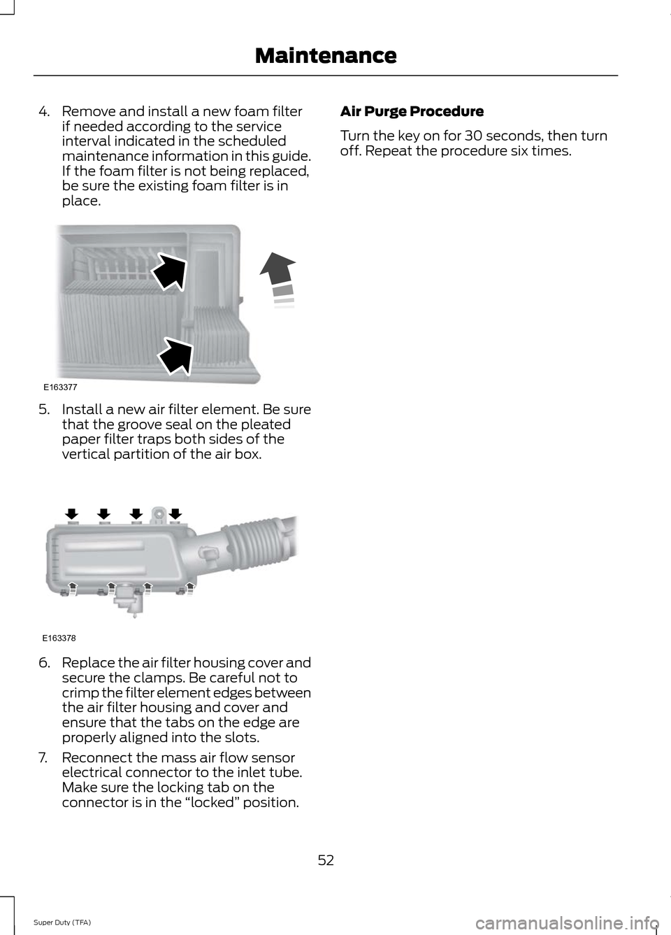
4. Remove and install a new foam filter
if needed according to the service
interval indicated in the scheduled
maintenance information in this guide.
If the foam filter is not being replaced,
be sure the existing foam filter is in
place. 5. Install a new air filter element. Be sure
that the groove seal on the pleated
paper filter traps both sides of the
vertical partition of the air box. 6.
Replace the air filter housing cover and
secure the clamps. Be careful not to
crimp the filter element edges between
the air filter housing and cover and
ensure that the tabs on the edge are
properly aligned into the slots.
7. Reconnect the mass air flow sensor electrical connector to the inlet tube.
Make sure the locking tab on the
connector is in the “locked ” position. Air Purge Procedure
Turn the key on for 30 seconds, then turn
off. Repeat the procedure six times.
52
Super Duty (TFA) MaintenanceE163377 E163378