Page 158 of 403

PRINCIPLES OF OPERATION
WARNING:Vehicle modifications involving braking system,
aftermarket roof racks, suspension, steering system, tire
construction and wheel or tire size may change the handling
characteristics of your vehicle and may adversely affect the performance
of the AdvanceTrac® system. In addition, installing any stereo
loudspeakers may interfere with and adversely affect the AdvanceTrac®
system. Install any aftermarket stereo loudspeaker as far as possible from
the front center console, the tunnel, and the front seats in order to
minimize the risk of interfering with the AdvanceTrac® sensors. Reducing
the effectiveness of the AdvanceTrac® system could lead to an increased
risk of loss of vehicle control, vehicle rollover, personal injury and death.
WARNING:Remember that even advanced technology cannot
defy the laws of physics. It is always possible to lose control of a
vehicle due to inappropriate driver input for the conditions. Aggressive
driving on any road condition can cause you to lose control of your
vehicle increasing the risk of personal injury or property damage.
Activation of the AdvanceTrac® system is an indication that at least
some of the tires have exceeded their ability to grip the road; this could
reduce the operator’s ability to control the vehicle potentially resulting
in a loss of vehicle control, vehicle rollover, personal injury and death.
If your AdvanceTrac® system activates, SLOW DOWN.
The AdvanceTrac® system helps you keep control of your vehicle when
on a slippery surface. The electronic stability control portion of the
system helps avoid skids and lateral slides and the traction control
system helps avoid drive wheel spin and loss of traction. See the
Traction Controlchapter for details on traction control system
operation.
Stability Control157
2014 Focus Electric Vehicle(fob)
Owners Guide gf, 1st Printing, May 2013
USA(fus)
Page 160 of 403

SENSING SYSTEM (IF EQUIPPED)
WARNING:To help avoid personal injury, please read and
understand the limitations of the system as contained in this
section. Sensing is only an aid for some (generally large and fixed)
objects when moving in reverse on a flat surface at parking speeds.
Traffic control systems, inclement weather, air brakes, and external
motors and fans may also affect the function of the sensing system; this
may include reduced performance or a false activation.
WARNING:To help avoid personal injury, always use caution
when the transmission is inRand when using the sensing system.
WARNING:This system is not designed to prevent contact with
small or moving objects. The system is designed to provide a
warning to assist the driver in detecting large stationary objects to
avoid damaging the vehicle. The system may not detect smaller objects,
particularly those close to the ground.
WARNING:Certain add-on devices, such as large trailer hitches,
bike or surfboard racks and any device that may block the normal
detection zone of the system, may create false beeps.
Note:
Keep the sensors (located on the bumper/fascia) free from snow, ice
and large accumulations of dirt. If the sensors are covered, the system’s
accuracy can be affected. Do not clean the sensors with sharp objects.
Note:If your vehicle sustains damage to the bumper/fascia, leaving it
misaligned or bent, the sensing zone may be altered causing inaccurate
measurement of obstacles or false alarms.
The sensing system warns the driver of obstacles within a certain range
of the bumper area. The system turns on automatically whenever the
ignition is switched on.
When receiving a detection warning, the radio volume is reduced to a
predetermined level. After the warning goes away, the radio volume
returns to the previous level.
The system can be turned off using the information display control. See
theInformation Displaychapter. If a fault is present in the system, a
warning message appears in the information display and does not allow
the driver to switch the faulted system on.
Parking Aids159
2014 Focus Electric Vehicle(fob)
Owners Guide gf, 1st Printing, May 2013
USA(fus)
Page 161 of 403

Using the Rear Sensing System
The rear sensors are only active when the transmission is inR.Asthe
vehicle moves closer to the obstacle, the rate of the audible warning
increases. When the obstacle is fewer than 12 inches (30 centimeters)
away, the warning sounds continuously. If a stationary or receding object
is detected farther than 12 inches (30 centimeters) from the side of the
vehicle, the tone sounds for only three seconds. Once the system detects
an object approaching, the warning sounds again.
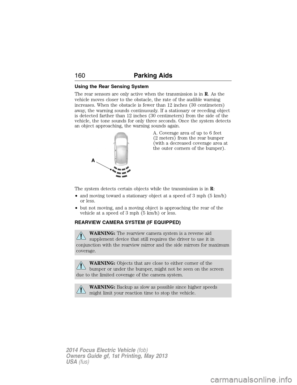
A. Coverage area of up to 6 feet
(2 meters) from the rear bumper
(with a decreased coverage area at
the outer corners of the bumper).
The system detects certain objects while the transmission is inR:
•and moving toward a stationary object at a speed of 3 mph (5 km/h)
or less.
•but not moving, and a moving object is approaching the rear of the
vehicle at a speed of 3 mph (5 km/h) or less.
REARVIEW CAMERA SYSTEM (IF EQUIPPED)
WARNING:The rearview camera system is a reverse aid
supplement device that still requires the driver to use it in
conjunction with the rearview mirror and the side mirrors for maximum
coverage.
WARNING:Objects that are close to either corner of the
bumper or under the bumper, might not be seen on the screen
due to the limited coverage of the camera system.
WARNING:Backup as slow as possible since higher speeds
might limit your reaction time to stop the vehicle.
A
160Parking Aids
2014 Focus Electric Vehicle(fob)
Owners Guide gf, 1st Printing, May 2013
USA(fus)
Page 201 of 403
The high-current fuses are coded as follows:
Fuse or relay
locationFuse amp
ratingProtected circuits
F7 40A** Anti-lock brakes pump
F8 30A** Anti-lock brakes valve
F9 — Not used
F10 40A** Heater blower motor,
Temperature sensor
F11 40A** Vacuum pump
F12 40A** Motor control relay fuse
F13 40A** On-board charger
F14 40A** Heater element 1
F15 — Not used
F16 40A** Heater element 2
F17 — Not used
F30 F31
F24 F21 F20
F25 F22
F23F17
R10R9 R6
F15F19 F8 F7
F37
F38
F39
F40
F41 F43
F42
F44
F45 F46
F48
F47 F13 F11 F9
F16 F14 F12 F10
R11
R8R7R16R15
R3
R5 R4 R2R1
F18 F26 F27 F32
F33
F34
F35 F28
F29
R12
R13 R14
F36
200Fuses
2014 Focus Electric Vehicle(fob)
Owners Guide gf, 1st Printing, May 2013
USA(fus)
Page 202 of 403

Fuse or relay
locationFuse amp
ratingProtected circuits
F18 20A** Front wiper motor
F19 5A* Anti-lock brake control module
F20 15A* Horn
F21 5A* Stop light switch
F22 15A* Battery monitoring sensor
F23 5A* Relay coils
F24 5A* Light switch module
F25 — Not used
F26 10A* Powertrain control module
F27 15A* Charger port light ring
F28 5A* Vacuum pump monitor
F29 — Not used
F30 5A* Transmission control module
F31 10A* Smart datalink connector;
Diagnostic connector
F32 10A* Compressor bypass valves,
Coolant valves, Electronic fan
control module relay
F33 10A* Powertrain control module (PSR
feedback), A/C compressor
solenoid
F34 15A* Powertrain control module
(contactor sense), Battery
electronics control module (PSR)
F35 — Not used
F36 20A* Coolant water pumps
F37 5A* Vehicle audible speaker for
pedestrians
F38 15A* Powertrain control module
(electronic control module KL15)
F39 5A* Not used (spare)
F40 5A* Electronic power assist steering
Fuses201
2014 Focus Electric Vehicle(fob)
Owners Guide gf, 1st Printing, May 2013
USA(fus)
Page 203 of 403
Fuse or relay
locationFuse amp
ratingProtected circuits
F41 20A* Body control module
F42 15A* Rear wiper
F43 15A* Not used (spare)
F44 — Not used
F45 — Not used
F46 — Not used
F47 5A* In-Car temperature sensor
F48 5A* Mechanical relay
R1 — Not used
R2 Micro relay Horn relay
R3 — Not used
R4 Micro relay Contactor relay
R5 — Not used
R6 — Not used
R7 Power relay Heater element 3
R8 Power relay Heater element1&2
R9 — Not used
R10 Mini relay Anti-lock brake system vacuum
pump (solid state relay)
R11 — Not used
R12 Power relay Electronic fan control module
relay
R13 Mini relay Heater blower relay
R14 Mini relay Motor control relay
R15 Power relay Mechanical relay
R16 Power relay Ignition 15
*Mini Fuses **Cartridge Fuses
202Fuses
2014 Focus Electric Vehicle(fob)
Owners Guide gf, 1st Printing, May 2013
USA(fus)
Page 204 of 403
Passenger Compartment Fuse Panel
The fuse panel is located on the right side below the glove box.
Fuse or relay
numberFuse amp
ratingProtected components
F56 20A Not used (spare)
F57 — Not used
F58 — Not used
F59 5A Passive anti-theft transceiver
F60 10A Interior light, Driver door switch
pack, Glove box illumination,
Overhead console switch bank
F61 20A Cigar lighter, Power point
F62 5A Rain sensor module
F63 — Not used
F64 — Not used
F65 10A Liftgate release
Fuses203
2014 Focus Electric Vehicle(fob)
Owners Guide gf, 1st Printing, May 2013
USA(fus)
Page 205 of 403

Fuse or relay
numberFuse amp
ratingProtected components
F66 20A Driver door unlock supply
F67 7.5A SYNC, Multifunction display,
Global positioning system module,
Compass
F68 — Not used
F69 5A Instrument cluster
F70 20A Central lock and unlock supply
F71 10A Climate control
F72 7.5A Steering wheel module
F73 7.5A Datalink connector
F74 15A Low beam headlamp supply
F75 15A Not used (spare)
F76 10A Reversing lamp supply,
Auto-dimming rear view mirror
F77 20A Washer pump
F78 5A Ignition switch, Start button
F79 15A Radio, Hazard light switch, Door
lock switch, Electronic finish
panel
F80 20A Not used (spare)
F81 5A Radio frequency receiver
F82 20A Washer pump ground
F83 20A Central locking ground
F84 20A Unlock supply ground
F85 7.5A Front seat heater switch
F86 10A Airbag module, Occupant
classification sensor, Passenger
airbag deactivation indicator
F87 — Not used
F88 25A Supply for F67, F69, F71 and F79
F89 — Not used
204Fuses
2014 Focus Electric Vehicle(fob)
Owners Guide gf, 1st Printing, May 2013
USA(fus)