2014 FORD F250 park assist
[x] Cancel search: park assistPage 171 of 460

PRINCIPLE OF OPERATION
WARNINGS
Hill descent control cannot control
descent in all surface conditions and
circumstances, such as ice or
extremely steep grades. Hill descent
control is a driver assist system and cannot
substitute for good judgment by the driver.
Failure to do so may result in loss of vehicle
control, crash or serious injury. Hill descent control does not provide
hill hold at zero miles per hour (0
kilometers per hour). When stopped,
the parking brake must be applied or the
vehicle must be placed in P (Park) or it
may roll away. Hill descent control allows the driver to set
and maintain vehicle speed while
descending steep grades in various surface
conditions.
Hill descent control can maintain vehicle
speeds on downhill grades between 2 mph
(3 km/h) and 12 mph (20 km/h). Above 20
mph (32 km/h), the system remains
armed, but descent speed cannot be set
or maintained.
Hill descent control requires a cooling
down interval after a period of sustained
use. The amount of time that the feature
can remain active before cooling varies
with conditions. The system will provide a
warning in the message center and a chime
will sound when the system is about to
disengage for cooling. At this time,
manually apply the brakes as needed to
maintain descent speed. USING HILL DESCENT
CONTROL Press and release the hill
descent button located on the
instrument panel. A light in the
cluster will illuminate and a
chime will sound when this feature is
activated.
To increase descent speed, press the
accelerator pedal until the desired speed
is reached. To decrease descent speed,
press the brake pedal until the desired
speed is reached.
Whether accelerating or decelerating, once
the desired descent speed is reached,
remove your feet from the pedals and the
chosen vehicle speed will be maintained.
Note: Noise from the ABS pump motor may
be observed during hill descent control
operation. This is a normal characteristic of
the ABS and should be no reason for
concern.
Hill descent modes
• At speeds below 20 mph (32 km/h):
When the Hill Descent Control switch
is pressed and Hill Descent Control is
active, the Hill Descent Control telltale
will flash.
• At speeds below 20 mph (32 km/h):
When the Hill Descent Control switch
is pressed and conditions are not
correct for hill descent activation, the
Hill Descent Control system will be
enabled, the Hill Descent Control
telltale will be solid and a message will
display in the information display.
168
Super Duty (TFA) Terrain Response
(If Equipped)E163957
Page 173 of 460

PARKING AID (IF EQUIPPED)
WARNINGS
To help avoid personal injury, please
read and understand the limitations
of the system as contained in this
section. Sensing is only an aid for some
(generally large and fixed) objects when
moving in reverse on a flat surface at
parking speeds. Traffic control systems,
inclement weather, air brakes, and external
motors and fans may also affect the
function of the sensing system; this may
include reduced performance or a false
activation. To help avoid personal injury, always
use caution when in R (Reverse) and
when using the sensing system.
This system is not designed to
prevent contact with small or moving
objects. The system is designed to
provide a warning to assist the driver in
detecting large stationary objects to avoid
damaging the vehicle. The system may not
detect smaller objects, particularly those
close to the ground. Certain add-on devices such as large
trailer hitches, bike or surfboard racks
and any device that may block the
normal detection zone of the system, may
create false beeps. Note:
Keep the sensors, located on the
bumper or fascia, free from snow, ice and
large accumulations of dirt. If the sensors
are covered, the system ’s accuracy can be
affected. Do not clean the sensors with
sharp objects.
Note: If your vehicle sustains damage to
the bumper or fascia, leaving it misaligned
or bent, the sensing zone may be altered
causing inaccurate measurement of
obstacles or false alarms. Note:
If your vehicle is equipped with
MyKey ™, it is possible to prevent turning
the sensing system off. See MyKey ™
(page
50).
Note: If your vehicle is equipped with a fully
integrated electronic trailer brake controller
(TBC) and a trailer with electric trailer
brakes is connected to your vehicle, the RSS
will be disabled. When the vehicle is shifted
into reverse, the information display will
remain in the Rear Park Aid Off selection.
For more information on the TBC, See
Trailer Sway Control
(page 188).
The sensing system warns the driver of
obstacles within a certain range of the
bumper area. The system turns on
automatically whenever the ignition is
switched on.
When receiving a detection warning, the
radio volume is reduced to a
predetermined level. After the warning
goes away, the radio volume returns to the
previous level.
Rear Sensing System
The rear sensors are only active when the
transmission is in R (Reverse). As the
vehicle moves closer to the obstacle, the
rate of the audible warning increases.
When the obstacle is fewer than 12 inches
(30 centimeters) away, the warning
sounds continuously. If a stationary or
receding object is detected farther than 12
inches (30 centimeters) from the side of
the vehicle, the tone sounds for only three
seconds. Once the system detects an
object approaching, the warning sounds
again.
170
Super Duty (TFA) Parking Aids
Page 209 of 460

Park the booster vehicle close to the hood
of the disabled vehicle, making sure the
two vehicles do not touch. Turn all
accessories off.
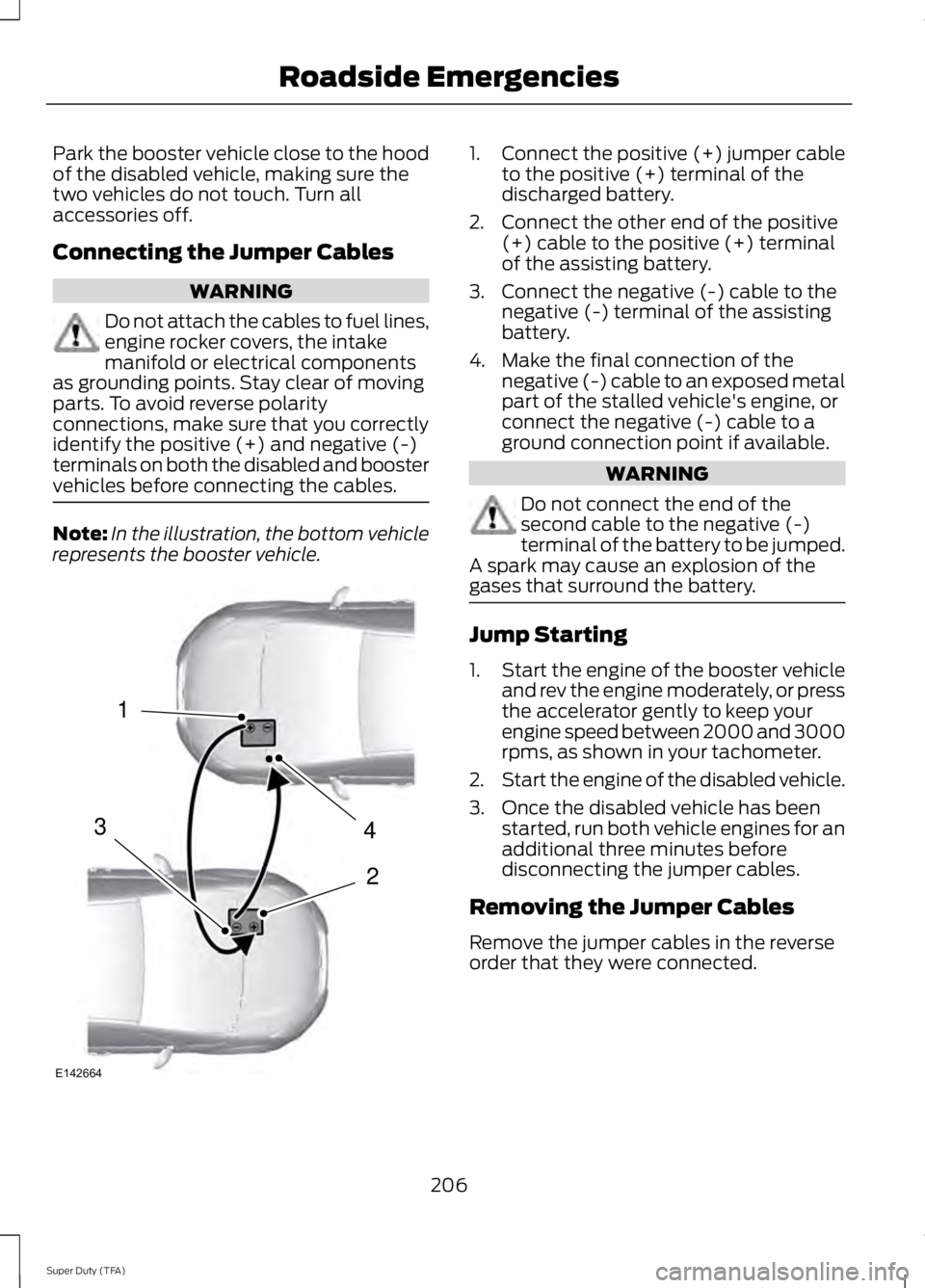
Connecting the Jumper Cables
WARNING
Do not attach the cables to fuel lines,
engine rocker covers, the intake
manifold or electrical components
as grounding points. Stay clear of moving
parts. To avoid reverse polarity
connections, make sure that you correctly
identify the positive (+) and negative (-)
terminals on both the disabled and booster
vehicles before connecting the cables. Note:
In the illustration, the bottom vehicle
represents the booster vehicle. 1.
Connect the positive (+) jumper cable
to the positive (+) terminal of the
discharged battery.
2. Connect the other end of the positive (+) cable to the positive (+) terminal
of the assisting battery.
3. Connect the negative (-) cable to the negative (-) terminal of the assisting
battery.
4. Make the final connection of the negative (-) cable to an exposed metal
part of the stalled vehicle's engine, or
connect the negative (-) cable to a
ground connection point if available. WARNING
Do not connect the end of the
second cable to the negative (-)
terminal of the battery to be jumped.
A spark may cause an explosion of the
gases that surround the battery. Jump Starting
1.
Start the engine of the booster vehicle
and rev the engine moderately, or press
the accelerator gently to keep your
engine speed between 2000 and 3000
rpms, as shown in your tachometer.
2. Start the engine of the disabled vehicle.
3. Once the disabled vehicle has been started, run both vehicle engines for an
additional three minutes before
disconnecting the jumper cables.
Removing the Jumper Cables
Remove the jumper cables in the reverse
order that they were connected.
206
Super Duty (TFA) Roadside Emergencies4
2
1
3
E142664
Page 214 of 460

In the CAMVAP program, impartial
third-party arbitrators conduct hearings at
mutually convenient times and places in
an informal environment. These impartial
arbitrators review the positions of the
parties, make decisions and, when
appropriate, render awards to resolve
disputes. CAMVAP decisions are fast, fair,
and final as the arbitrator
’s award is
binding on both you and Ford of Canada.
CAMVAP services are available in all
Canadian territories and provinces. For
more information, without charge or
obligation, call your CAMVAP Provincial
Administrator directly at 1-800-207-0685
or visit www.camvap.ca.
GETTING ASSISTANCE
OUTSIDE THE U.S. AND
CANADA
Before exporting your vehicle to a foreign
country, contact the appropriate foreign
embassy or consulate. These officials can
inform you of local vehicle registration
regulations and where to find unleaded
fuel.
If you cannot find unleaded fuel or can only
get fuel with an anti-knock index lower
than is recommended for your vehicle,
contact our Customer Relationship Center.
The use of leaded fuel in your vehicle
without proper conversion may damage
the effectiveness of your emission control
system and may cause engine knocking or
serious engine damage. Ford Motor
Company or Ford of Canada is not
responsible for any damage caused by use
of improper fuel. Using leaded fuel may
also result in difficulty importing your
vehicle back into the United States. If your vehicle must be serviced while you
are traveling or living in Asia-Pacific Region,
Sub-Saharan Africa, U.S. Virgin Islands,
Central America, the Caribbean, and Israel,
contact the nearest authorized dealer. If
the authorized dealer cannot help you,
contact:
FORD MOTOR COMPANY
FORD EXPORT OPERATIONS & GLOBAL
INITIATIVES
Customer Relationship Center
1555 Fairlane Drive
Fairlane Business Park #3
Allen Park, Michigan 48101
U.S.A.
Telephone: (313) 594-4857
Fax: (313) 390-0804
Email: [email protected]
For customers in Guam, the
Commonwealth of the Northern Mariana
Islands (CNMI), America Samoa, and the
U.S. Virgin Islands, please feel free to call
our Toll-Free Number: (800) 841-FORD
(3673).
If your vehicle must be serviced while you
are traveling or living in Puerto Rico,
contact the nearest authorized dealer. If
the authorized dealer cannot help you,
contact:
FORD MOTOR COMPANY
FORD EXPORT OPERATIONS & GLOBAL
INITIATIVES
Customer Relationship Center
1555 Fairlane Drive
Fairlane Business Park #3
Allen Park, Michigan 48101
U.S.A.
Telephone: (800) 841-FORD (3673)
FAX: (313) 390-0804
Email: [email protected]
www.ford.com.pr
If your vehicle must be serviced while you
are traveling or living in the Middle East,
contact the nearest authorized dealer. If
the authorized dealer cannot help you,
contact:
211
Super Duty (TFA) Customer Assistance
Page 281 of 460

•
To reduce the chances of interference
from another vehicle, perform the
system reset procedure at least three
feet (one meter) away from another
Ford Motor Company vehicle
undergoing the system reset procedure
at the same time.
• Do not wait more than two minutes
between resetting each tire sensor or
the system will time-out and the entire
procedure will have to be repeated on
all four wheels.
• A double horn will sound indicating the
need to repeat the procedure.
Performing the System Reset Procedure
Read the entire procedure before
attempting.
1. Drive the vehicle above 20 mph (32 km/h) for at least two minutes, then
park in a safe location where you can
easily get to all four tires and have
access to an air pump.
2. Place the ignition in the off position and
keep the key in the ignition.
3. Cycle the ignition to the on position with the engine off.
4. Turn the hazard flashers on then off three times. You must accomplish this
within 10 seconds. If the reset mode
has been entered successfully, the horn
will sound once, the system indicator
will flash and a message is shown in
the information display. If this does not
occur, please try again starting at Step
2. If after repeated attempts to enter
the reset mode, the horn does not
sound, the system indicator does not
flash and no message is shown in the
information display, seek service from
your authorized dealer. 5. Train the tire pressure monitoring
system sensors in the tires using the
following system reset sequence
starting with the left front tire in the
following clockwise order: Left front
(driver's side front tire), Right front
(passenger's side front tire), Right rear
(passenger's side rear tire), Left rear
(driver's side rear tire)
6. Remove the valve cap from the valve stem on the left front tire. Decrease the
air pressure until the horn sounds.
Note: The single horn chirp confirms
that the sensor identification code has
been learned by the module for this
position. If a double horn is heard, the
reset procedure was unsuccessful, and
you must repeat it.
7. Remove the valve cap from the valve stem on the right front tire. Decrease
the air pressure until the horn sounds.
8. Remove the valve cap from the valve stem on the right rear tire. Decrease the
air pressure until the horn sounds.
9. Remove the valve cap from the valve stem on the left rear tire. Decrease the
air pressure until the horn sounds.
Training is complete after the horn
sounds for the last tire trained (driver's
side rear tire), the system indicator
stops flashing, and a message is shown
in the information display.
10. Turn the ignition off. If two short horn
beeps are heard, the reset procedure
was unsuccessful and you must
repeat it. If after repeating the
procedure and two short beeps are
heard when the ignition is turned to
off, seek assistance from your
authorized dealer.
278
Super Duty (TFA) Wheels and Tires
Page 356 of 460

Restricted features
Editing settings while the rear view camera or active park
assist are active
Editing wireless settings
Wi-Fi and Wireless
Editing the list of wireless networks
Playing video
Videos, Photos and Graphics
Editing the screen's wallpaper or adding new wallpaper
Composing text messages
Text Messages
Viewing received text messages
Editing preset text messages
Using the keyboard to enter a destination
Navigation
Demo navigation route
Adding or editing Address Book entries or Avoid Areas
Privacy Information
When you connect a cellular phone to
SYNC, the system creates a profile within
your vehicle that links to that cellular
phone. This profile helps in offering you
more cellular features and operating more
efficiently. Among other things, this profile
may contain data about your cellular
phone book, text messages (read and
unread), and call history, including history
of calls when your cell phone was not
connected to the system. In addition, if you
connect a media device, the system
creates and retains an index of supported
media content. The system also records a
short development log of approximately
10 minutes of all recent system activity.
The log profile and other system data may
be used to improve the system and help
diagnose any problems that may occur. The cellular profile, media device index,
and development log remain in your
vehicle unless you delete them and are
generally accessible only in your vehicle
when the cellular phone or media player
is connected. If you no longer plan to use
the system or your vehicle, we recommend
you perform a Master Reset to erase all
stored information.
System data cannot be accessed without
special equipment and access to your
vehicle's SYNC module. Ford Motor
Company and Ford of Canada do not
access the system data for any purpose
other than as described absent consent, a
court order, or where required by law
enforcement, other government
authorities, or other third parties acting
with lawful authority. Other parties may
seek to access the information
independently of Ford Motor Company and
Ford of Canada. For further privacy
information, see the sections on 911 Assist,
Vehicle Health Report, and Traffic,
Directions and Information.
353
Super Duty (TFA) MyFord Touch
™ (If Equipped)
Page 453 of 460

Fuel Consumption........................................138
Calculating Fuel Economy.............................. 138
Filling the Tank.................................................... 138
Fuel Filter
........................................................235
Fuel Quality.....................................................135
Choosing the Right Fuel................................... 135
Choosing the Right Fuel With a Flex Fuel Vehicle (If Equipped)................................... 135
Diesel Engine........................................................ 135
Octane Recommendations............................ 135
Fuel Shutoff
..................................................205
Fuses.................................................................214
Fuse Specification Chart............................215 Passenger Compartment Fuse
Panel................................................................. 220
Power Distribution Box..................................... 215
G
Garage Door Opener See: Universal Garage Door Opener.............119
Gauges................................................................75 Engine Coolant Temperature Gauge.............76
Engine Oil Pressure Gauge................................ 76
Fuel Gauge.............................................................. 76
Information Display.............................................. 77
Transmission Fluid Temperature Gauge................................................................... 76
General Information on Radio Frequencies...................................................46
General Maintenance Information.......430 Multi-point Inspection..................................... 432
Owner Checks and Services........................... 431
Protecting Your Investment.......................... 430
Why Maintain Your Vehicle?......................... 430
Why Maintain Your Vehicle at Your Dealership?..................................................... 430
Getting Assistance Outside the U.S. and Canada...........................................................211
Getting the Services You Need..............208 Away From Home............................................. 208
Global Opening...............................................70 Opening the Windows........................................ 70
H
Handbrake See: Parking Brake.............................................. 161Hazard Warning Flashers
.........................205
HDC See: Using Hill Descent Control.................... 168
Head Restraints............................................108 Adjusting the Head Restraint........................ 109
Heated Seats...................................................115
Heated Steering Wheel
................................62
Heated Windows and Mirrors..................106
Heated Exterior Mirror...................................... 106
Heated Rear Window....................................... 106
Heating See: Climate Control......................................... 103
Hill Start Assist...............................................161 Using Hill Start Assist........................................ 161
Hints on Controlling the Interior Climate..........................................................105
Hints on Driving With Anti-Lock Brakes............................................................160
Hood Lock See: Opening and Closing the Hood...........223
I
Ignition Switch
...............................................130
In California (U.S. Only)............................209
Information Display Control
........................61
Type 1........................................................................\
. 61
Type 2....................................................................... 62
Information Displays
......................................81
General Information............................................. 81
Information....................................................389 911 Assist............................................................... 395
Alerts...................................................................... 395
Calendar............................................................... 395
Sirius Travel Link................................................ 392
SYNC Services (If Equipped, United States Only)................................................................. 390
Vehicle Health Report...................................... 397
450
Super Duty (TFA) Index