2014 FIAT DUCATO BASE CAMPER clock
[x] Cancel search: clockPage 72 of 367

SLIDING SIDE WINDOW
(for versions/markets, where provided)
To open, keep the two handles B fig.
110 pressed toward one another and
slide the window.
When the two handles are released, the
sliding glass may stop in intermediate
positions.
MOVING FOOTBOARD
(for versions/markets, where provided)
When the side door of the passenger
compartment or luggage compartment
is opened, a footboard fig. 111
emerges from the lower part of the
floorpan to make it easier to get on
board the vehicle.
37)
REAR DOOR WITH TWO
WINGS
Manual opening of the
first swing door from
the outside
Turn the key anticlockwise fig. 106 or
press the
button on the remote
control and turn handle A fig. 112 in the
direction of the arrow.Manual opening of the
first swing door from
the inside
(for versions/markets, where provided)
Pull handle B fig. 113 in the direction
of the arrow.
Manual closure of the
first swing door from
the outside
Turn the key clockwise or press the
button on the key with remote
control. Close the left door first,
followed by the right door.
Manual opening of the
second swing door
Pull handle C fig. 114 in the direction of
the arrow.
110
F1A0118
111
F1A0119
112
F1A0120
113
F1A0121
68
KNOW YOUR VEHICLE
Page 105 of 367

When using or parking the vehicle for a
long time in the mountains or cold
areas, it is advisable to refuel using
locally available diesel fuel.
In this case, it is also advisable to keep
the tank over 50% full.
18)
FILLING THE TANK
To fill the tank completely, top-up twice
after the first click of the fuel supply
gun. Further top-ups could cause faults
in the fuel supply system.
FUEL TANK CAP
For refuelling, open flap A fig. 140 and
unscrew cap B turning the ignition
key anticlockwise; the cap is fitted with
a safety device C which fastens it to
the flap so it cannot be mislaid.The sealing may cause a slight pressure
increase in the tank. A little breathing
off, while slackening the cap is
absolutely normal.
When refuelling, fasten the cap to the
device inside the flap as shown in
fig. 140.
88)
IMPORTANT
18) Only refuel with automotive
diesel complying with the
European specification EN 590.
The use of other products or
mixtures may damage the engine
beyond repair and consequently
invalidate the warranty, due to the
damage caused. If you
accidentally introduce other types
of fuel into the tank, do not start
the engine. Empty the tank. If the
engine has been run for even an
extremely limited amount of time,
you must not only drain the fuel
tank, but the rest of the supply
circuit as well.
WARNING
88) Do not bring naked flames or lit
cigarettes near to the fuel tank
opening: fire risk. Keep your face
away from the fuel filler to prevent
breathing in harmful vapours.PROTECTING THE
ENVIRONMENTThe following devices are used for
reducing diesel fuel engine emissions:
❒oxidising catalytic converter;
❒exhaust gas recirculation system
(EGR);
❒particulate filter (DPF) (for versions/
markets, where provided).
89)
DIESEL PARTICULATE
FILTER (DPF)
The Diesel Particulate Filter is a
mechanical filter, integral to the exhaust
system, that physically traps carbon
particles present in the exhaust gases
of diesel engines.
140
F1A0144
101
Page 115 of 367

Setup menu
- within the menu, they allow you to
scroll up and down;
- during setting operations they allow
an increase or decrease.
SETUP MENU
Setup menu functions
The menu comprises a series of
functions arranged in a circular way,
which can be selected through the
and
buttons to access the
different selection operations and
settings (setup) given in the following
paragraphs. A submenu is provided for
some items (Clock and Unit setting).
The setup menu can be activated
by pressing the MODE button briefly.
The menu comprises the following
functions:
❒Menu
❒Lighting
❒Headlight alignment corrector
❒Speed warning
❒Headlight sensor
❒Cornering lights
❒Rain sensor
❒Trip B activation❒Traffic sign
❒Set time
❒Set date
❒Autoclose
❒Units of measurement
❒Language
❒Warning volume
❒Service
❒Passenger airbag
❒Daytime Running Lights
❒Automatic main beam headlights
❒Exit menu
Single presses of the
or
buttons permit navigation
through the setup menu options.
Operating modes are different
according to the characteristics of the
option selected.
Selecting an option from the main
menu without a submenu:
- briefly press the MODE button to
select the main menu option that needs
to be changed;
- press the
or
buttons (with
a single press) to select the new
setting;- briefly press the MODE button to
store the new setting and at the same
time go back to the previously selected
menu option.
Selecting an option from the main
menu with a submenu:
- briefly press the MODE button to
display the first submenu option;
- press the
or
buttons (with
a single press) to scroll through all
submenu options;
- briefly press the MODE button to
select the displayed submenu option
and to open the relevant settings menu;
- press the
or
buttons
(with a single press) to choose the new
setting for this submenu option;
- briefly press the MODE button to
store the setting and return to the
previously selected submenu option.
Selecting “Date” and “Set Clock”:
- briefly press the MODE button to
select the first value to be changed (e.g.
hours / minutes or year / month / day);
- press the
or
buttons (with
a single press) to select the new
setting;
111
Page 118 of 367

❒press
or
to make your
choice;
❒briefly press the MODE button to
return to the menu screen or hold the
button down to return to the
standard screen without storing.
Rain sensor
(Rain sensor setting adjustment)
(for versions/markets, where provided)
This function allows you to adjust the
rain sensor sensitivity to 4 levels.
To set the required sensitivity level,
proceed as follows:
❒briefly press the MODE button. The
sensitivity “level” set previously
flashes on the display;
❒press the
or
button to
make the adjustment;
❒briefly press the MODE button to
return to the menu screen or hold the
button down to return to the
standard screen without storing.
Trip B On/Off (Trip B
data)
This function can be used to activate
(On) or deactivate (Off) the Trip B
display (partial trip).
For more information see the "Trip
computer" paragraph.For activation/deactivation, proceed as
follows:
- briefly press the MODE button: ON or
OFF flashes on the display (depending
the previous setting);
- press the
or
button to
select;
- press the MODE button briefly to
return to the menu screen or hold the
button down to return to the standard
screen without storing.
Traffic sign
This function allows you to activate (On)
or deactivate (Off) the Traffic Sign
function to recognise the traffic signs
(no overtaking or speed limits).
For activation/deactivation, proceed as
follows:
- briefly press the MODE button: ON or
OFF flashes on the display (depending
the previous setting);
- press the
or
button to
select;
- press the MODE button briefly to
return to the menu screen or hold the
button down to return to the standard
screen without storing.Setting the clock (Set
time)
This function allows you to set the clock
through two submenus: “Time” and
“Format”.
To carry out the adjustment, proceed as
follows:
- briefly press the MODE button and
two submenus, "Time" and "Format",
will be displayed;
- press the
or
button to
switch between the two submenus;
- once you have selected the submenu
to be changed, press button MODE
briefly;
- if you enter the "Time" submenu,
pressing the MODE button briefly
makes the "hours" flash on the display;
- press the
or
button to
adjust;
- briefly press the MODE button: the
"minutes" starts to flash on the display;
- press the
or
button to
adjust;
– if you enter the "Format" submenu,
pressing the MODE button briefly
makes the display format flash on the
display;
- press the
or
button to
select "24h" or "12h" mode.
114
KNOWING THE INSTRUMENT PANEL
Page 196 of 367

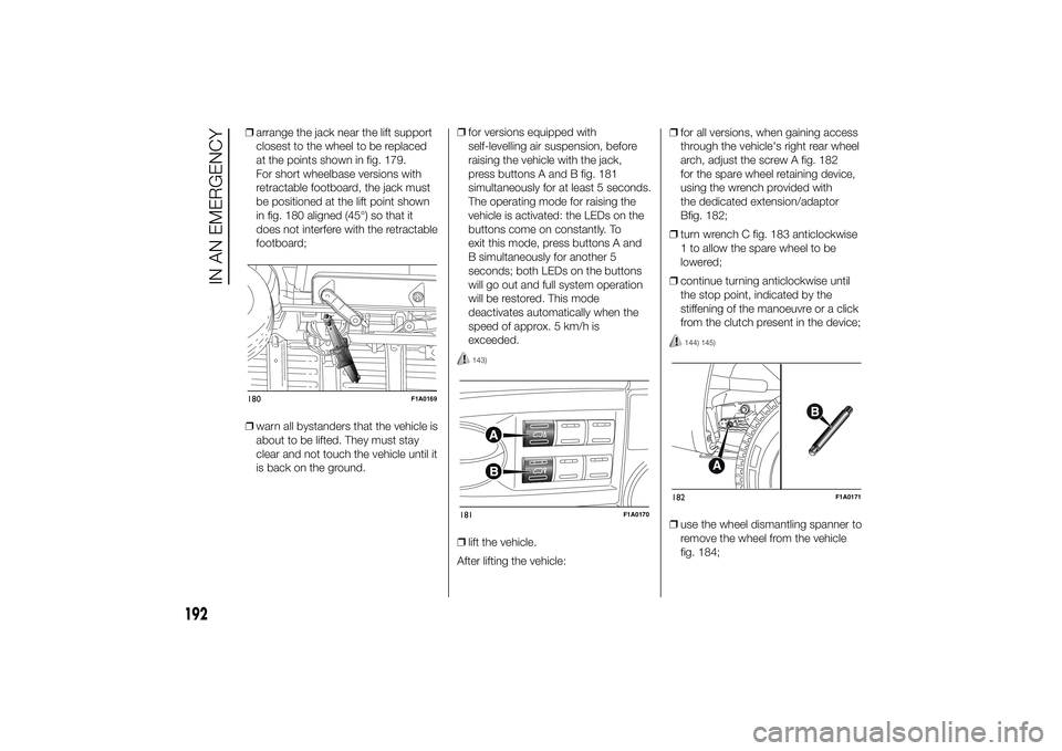
❒arrange the jack near the lift support
closest to the wheel to be replaced
at the points shown in fig. 179.
For short wheelbase versions with
retractable footboard, the jack must
be positioned at the lift point shown
in fig. 180 aligned (45°) so that it
does not interfere with the retractable
footboard;
❒warn all bystanders that the vehicle is
about to be lifted. They must stay
clear and not touch the vehicle until it
is back on the ground.❒for versions equipped with
self-levelling air suspension, before
raising the vehicle with the jack,
press buttons A and B fig. 181
simultaneously for at least 5 seconds.
The operating mode for raising the
vehicle is activated: the LEDs on the
buttons come on constantly. To
exit this mode, press buttons A and
B simultaneously for another 5
seconds; both LEDs on the buttons
will go out and full system operation
will be restored. This mode
deactivates automatically when the
speed of approx. 5 km/h is
exceeded.
143)
❒lift the vehicle.
After lifting the vehicle:❒for all versions, when gaining access
through the vehicle's right rear wheel
arch, adjust the screw A fig. 182
for the spare wheel retaining device,
using the wrench provided with
the dedicated extension/adaptor
Bfig. 182;
❒turn wrench C fig. 183 anticlockwise
1 to allow the spare wheel to be
lowered;
❒continue turning anticlockwise until
the stop point, indicated by the
stiffening of the manoeuvre or a click
from the clutch present in the device;
144) 145)
❒use the wheel dismantling spanner to
remove the wheel from the vehicle
fig. 184;
180
F1A0169
181
F1A0170
182
F1A0171
192
IN AN EMERGENCY
Page 197 of 367

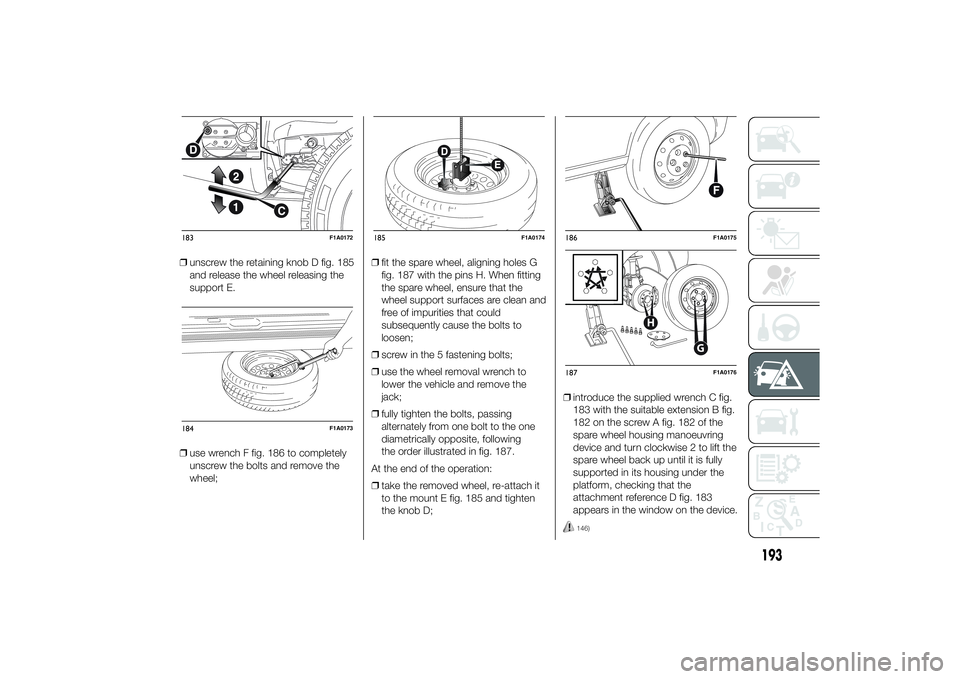
❒unscrew the retaining knob D fig. 185
and release the wheel releasing the
support E.
❒use wrench F fig. 186 to completely
unscrew the bolts and remove the
wheel;❒fit the spare wheel, aligning holes G
fig. 187 with the pins H. When fitting
the spare wheel, ensure that the
wheel support surfaces are clean and
free of impurities that could
subsequently cause the bolts to
loosen;
❒screw in the 5 fastening bolts;
❒use the wheel removal wrench to
lower the vehicle and remove the
jack;
❒fully tighten the bolts, passing
alternately from one bolt to the one
diametrically opposite, following
the order illustrated in fig. 187.
At the end of the operation:
❒take the removed wheel, re-attach it
to the mount E fig. 185 and tighten
the knob D;❒introduce the supplied wrench C fig.
183 with the suitable extension B fig.
182 on the screw A fig. 182 of the
spare wheel housing manoeuvring
device and turn clockwise 2 to lift the
spare wheel back up until it is fully
supported in its housing under the
platform, checking that the
attachment reference D fig. 183
appears in the window on the device.
146)
183
F1A0172
184
F1A0173
185
F1A0174
186
F1A0175
G
H
187
F1A0176
193
Page 198 of 367

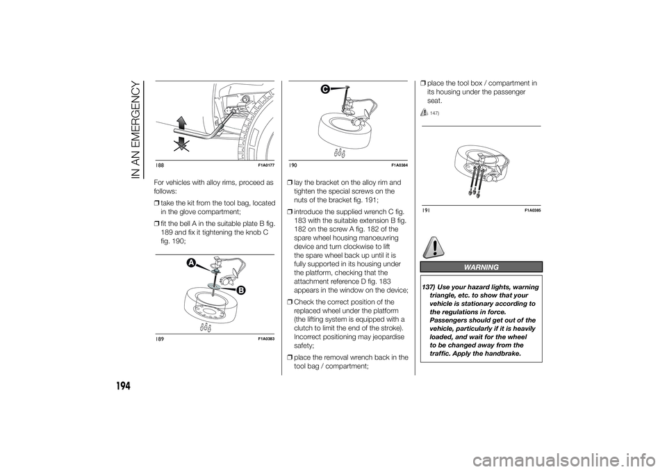
For vehicles with alloy rims, proceed as
follows:
❒take the kit from the tool bag, located
in the glove compartment;
❒fit the bell A in the suitable plate B fig.
189 and fix it tightening the knob C
fig. 190;❒lay the bracket on the alloy rim and
tighten the special screws on the
nuts of the bracket fig. 191;
❒introduce the supplied wrench C fig.
183 with the suitable extension B fig.
182 on the screw A fig. 182 of the
spare wheel housing manoeuvring
device and turn clockwise to lift
the spare wheel back up until it is
fully supported in its housing under
the platform, checking that the
attachment reference D fig. 183
appears in the window on the device;
❒Check the correct position of the
replaced wheel under the platform
(the lifting system is equipped with a
clutch to limit the end of the stroke).
Incorrect positioning may jeopardise
safety;
❒place the removal wrench back in the
tool bag / compartment;❒place the tool box / compartment in
its housing under the passenger
seat.
147)
WARNING
137) Use your hazard lights, warning
triangle, etc. to show that your
vehicle is stationary according to
the regulations in force.
Passengers should get out of the
vehicle, particularly if it is heavily
loaded, and wait for the wheel
to be changed away from the
traffic. Apply the handbrake.
188
F1A0177
189
F1A0383
190
F1A0384
191
F1A0385
194
IN AN EMERGENCY
Page 200 of 367

FIX&GO
AUTOMATIC QUICK
TYRE REPAIR KIT(for versions/markets, where provided)
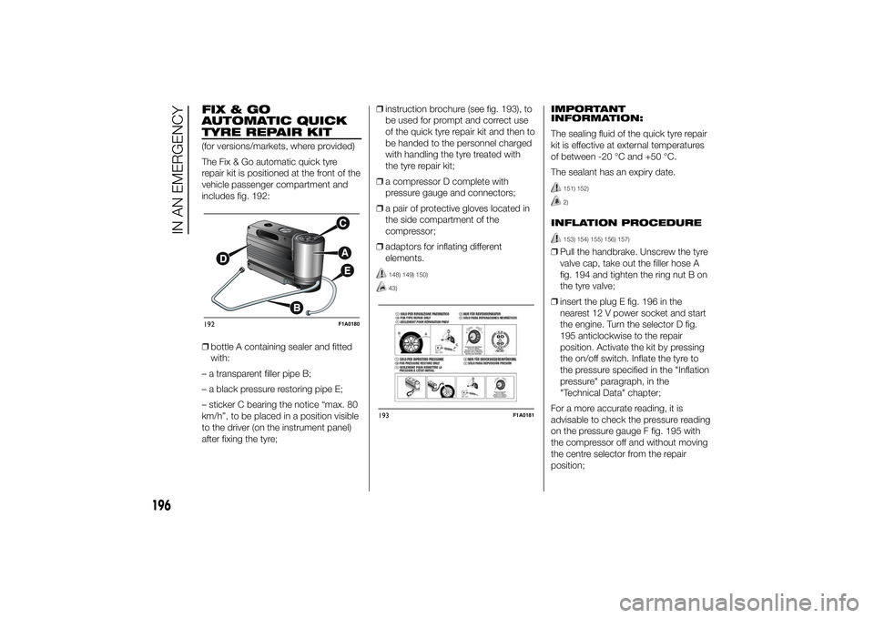
The Fix & Go automatic quick tyre
repair kit is positioned at the front of the
vehicle passenger compartment and
includes fig. 192:
❒bottle A containing sealer and fitted
with:
– a transparent filler pipe B;
– a black pressure restoring pipe E;
– sticker C bearing the notice “max. 80
km/h”, to be placed in a position visible
to the driver (on the instrument panel)
after fixing the tyre;❒instruction brochure (see fig. 193), to
be used for prompt and correct use
of the quick tyre repair kit and then to
be handed to the personnel charged
with handling the tyre treated with
the tyre repair kit;
❒a compressor D complete with
pressure gauge and connectors;
❒a pair of protective gloves located in
the side compartment of the
compressor;
❒adaptors for inflating different
elements.
148) 149) 150)43)
IMPORTANT
INFORMATION:
The sealing fluid of the quick tyre repair
kit is effective at external temperatures
of between -20 °C and +50 °C.
The sealant has an expiry date.
151) 152)2)
INFLATION PROCEDURE
153) 154) 155) 156) 157)
❒Pull the handbrake. Unscrew the tyre
valve cap, take out the filler hose A
fig. 194 and tighten the ring nut B on
the tyre valve;
❒insert the plug E fig. 196 in the
nearest 12 V power socket and start
the engine. Turn the selector D fig.
195 anticlockwise to the repair
position. Activate the kit by pressing
the on/off switch. Inflate the tyre to
the pressure specified in the "Inflation
pressure" paragraph, in the
"Technical Data" chapter;
For a more accurate reading, it is
advisable to check the pressure reading
on the pressure gauge F fig. 195 with
the compressor off and without moving
the centre selector from the repair
position;
192
F1A0180
193
F1A0181
196
IN AN EMERGENCY