2014 BMW Z4 SDRIVE28I service
[x] Cancel search: servicePage 97 of 285
If the tire inflation pressure in all four tires
is correct, the Tire Pressure Monitor may
not have been initialized. In this case, initi‐
alize the system.
Possible driving distance with complete loss of
tire inflation pressure:
The possible driving distance after a loss of tire
inflation pressure depends on the cargo load
and the driving style and conditions.
For a vehicle containing an average load, the
possible driving distance is approx.
50 miles/80 km.
When the vehicle is driven with a damaged tire,
its handling characteristics change, e.g., re‐
duced lane stability during braking, a longer
braking distance, and altered self-steering
properties. Adjust your driving style accord‐
ingly. Avoid abrupt steering maneuvers or driv‐
ing over obstacles, e. g., curbs, potholes, etc.
Because the possible driving distance de‐
pends on how the vehicle is used during the
trip, the actual distance may be smaller or
greater depending on the driving speed, road
conditions, external temperature, cargo load,
etc.
Continued driving with a flat tire
Drive moderately and do not exceed a
speed of 50 mph/80 km/h.
A loss of tire inflation pressure results in a
change in the handling characteristics, e.g., re‐
duced lane stability during braking, a longer
braking distance and altered self-steering
properties.◀
Final tire failure
Vibrations or loud noises while driving
can indicate the final failure of the tire. Reduce
speed and stop; otherwise, pieces of the tire
could come loose and cause an accident. Do
not continue driving, and contact your service
center.◀
Message when not reset
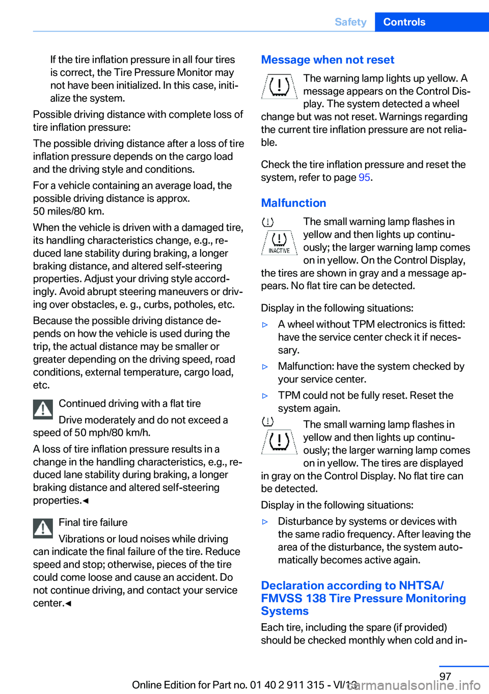
The warning lamp lights up yellow. A
message appears on the Control Dis‐
play. The system detected a wheel
change but was not reset. Warnings regarding
the current tire inflation pressure are not relia‐
ble.
Check the tire inflation pressure and reset the
system, refer to page 95.
Malfunction The small warning lamp flashes in
yellow and then lights up continu‐
ously; the larger warning lamp comes
on in yellow. On the Control Display,
the tires are shown in gray and a message ap‐
pears. No flat tire can be detected.
Display in the following situations:▷A wheel without TPM electronics is fitted:
have the service center check it if neces‐
sary.▷Malfunction: have the system checked by
your service center.▷TPM could not be fully reset. Reset the
system again.
The small warning lamp flashes in yellow and then lights up continu‐
ously; the larger warning lamp comes
on in yellow. The tires are displayed
in gray on the Control Display. No flat tire can
be detected.
Display in the following situations:
▷Disturbance by systems or devices with
the same radio frequency. After leaving the
area of the disturbance, the system auto‐
matically becomes active again.
Declaration according to NHTSA/
FMVSS 138 Tire Pressure Monitoring
Systems
Each tire, including the spare (if provided)
should be checked monthly when cold and in‐
Seite 97SafetyControls97
Online Edition for Part no. 01 40 2 911 315 - VI/13
Page 110 of 285
Microfilter
The microfilter removes dust and pollen from
the incoming air. The microfilter is changed byyour service center during routine mainte‐
nance work.
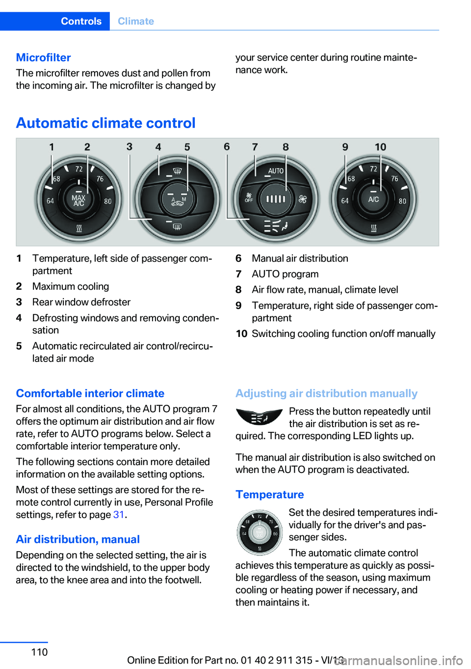
Automatic climate control
1Temperature, left side of passenger com‐
partment2Maximum cooling3Rear window defroster4Defrosting windows and removing conden‐
sation5Automatic recirculated air control/recircu‐
lated air mode6Manual air distribution7AUTO program8Air flow rate, manual, climate level9Temperature, right side of passenger com‐
partment10Switching cooling function on/off manuallyComfortable interior climate
For almost all conditions, the AUTO program 7
offers the optimum air distribution and air flow
rate, refer to AUTO programs below. Select a
comfortable interior temperature only.
The following sections contain more detailed
information on the available setting options.
Most of these settings are stored for the re‐
mote control currently in use, Personal Profile
settings, refer to page 31.
Air distribution, manual
Depending on the selected setting, the air is
directed to the windshield, to the upper body
area, to the knee area and into the footwell.Adjusting air distribution manually
Press the button repeatedly until
the air distribution is set as re‐
quired. The corresponding LED lights up.
The manual air distribution is also switched on
when the AUTO program is deactivated.
Temperature Set the desired temperatures indi‐
vidually for the driver's and pas‐
senger sides.
The automatic climate control
achieves this temperature as quickly as possi‐
ble regardless of the season, using maximum
cooling or heating power if necessary, and
then maintains it.Seite 110ControlsClimate110
Online Edition for Part no. 01 40 2 911 315 - VI/13
Page 113 of 285
area. This can be used to adjust the air
temperature for the upper body area.
Ventilation for cooling
Adjust the vents to direct the flow of cool air in
your direction, for instance if the interior has
become too warm.
Draft-free ventilation
Adjust the vents to let the air flow past you.
Microfilter/activated-charcoal filter
The microfilter traps dust and pollen in the in‐
coming air. The activated-charcoal filter pro‐
vides additional protection by filtering gaseous
pollutants from the outside air. Your service
center replaces this combined filter during rou‐
tine maintenance.
Seite 113ClimateControls113
Online Edition for Part no. 01 40 2 911 315 - VI/13
Page 114 of 285

Interior equipmentVehicle equipmentThis chapter describes all series equipment as
well as country-specific and special equipment
offered for this model series.Therefore, it also
describes equipment that may not be found in
your vehicle, for instance due to the selected
special equipment or the country version. This
also applies to safety-related functions and
systems.
Universal Garage Door
Opener
The concept The Universal Garage Door Opener can be
used to operate up to 3 functions in remote-
controlled systems, such as garage door drives or lighting systems. The Universal Garage
Door Opener replaces up to 3 different hand-
held transmitters. To operate it, the buttons on
the interior rearview mirror must be program‐
med for the desired functions. The hand-held
transmitter for the system is needed for the
programming procedure.
During programming
During programming and before activat‐
ing a device using the Universal Garage Door
Opener, ensure that there are no people, ani‐
mals, or objects in the range of movement of
the remote-controlled device; otherwise, there
is a risk of injury or damage.
Also follow the safety instructions of the hand-
held transmitter.◀
Before selling the vehicle, delete the stored
functions for security reasons.
Compatibility If this symbol is printed on the packag‐
ing or in the operating instructions ofthe system being operated, the system is gen‐
erally compatible with the Universal Garage
Door Opener.
If you have any questions, please contact:▷Your service center.▷www.homelink.com on the Internet.
HomeLink is a registered trademark of John‐
son Controls, Inc.
Controls on the interior rearview
mirror
1Buttons2LED3Hand-held transmitter, required for pro‐
gramming.
Programming
General information
1.Switch on the ignition.2.Initial setup:
Press the right and left buttons on the inte‐
rior rearview mirror simultaneously for ap‐
prox. 20 seconds until the LED on the inte‐
rior rearview mirror begins to flash. All
programmed settings of the buttons on the
interior rearview mirror are deleted.3.Hold the hand-held transmitter of the sys‐
tem to be operated a distance of approx. 1
to 3 in/2.5 to 8 cm away from the buttonsSeite 114ControlsInterior equipment114
Online Edition for Part no. 01 40 2 911 315 - VI/13
Page 121 of 285
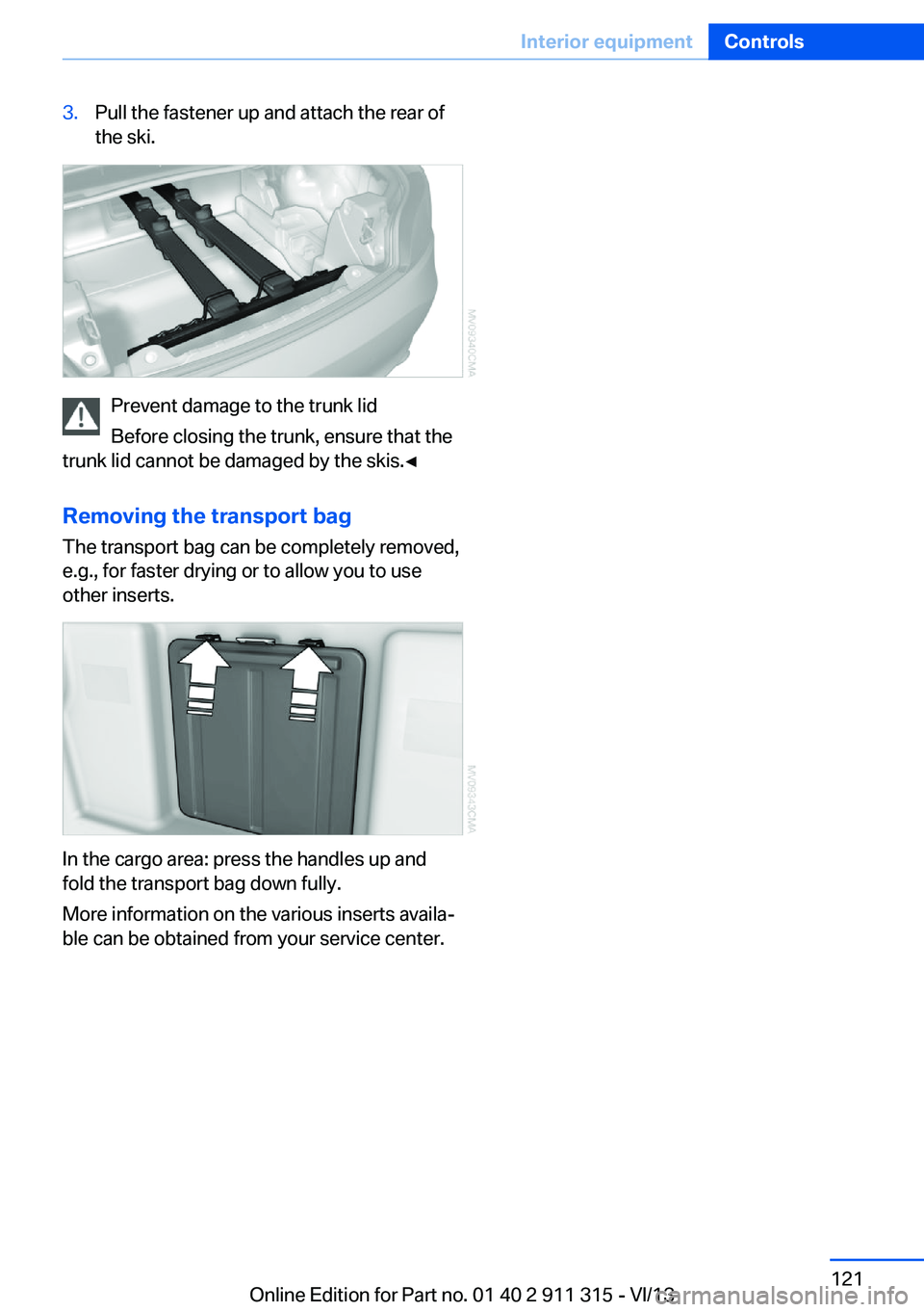
3.Pull the fastener up and attach the rear of
the ski.
Prevent damage to the trunk lid
Before closing the trunk, ensure that the
trunk lid cannot be damaged by the skis.◀
Removing the transport bag
The transport bag can be completely removed,
e.g., for faster drying or to allow you to use
other inserts.
In the cargo area: press the handles up and
fold the transport bag down fully.
More information on the various inserts availa‐
ble can be obtained from your service center.
Seite 121Interior equipmentControls121
Online Edition for Part no. 01 40 2 911 315 - VI/13
Page 123 of 285

Opening
Fold the center armrest up, see arrow.Connection for an external audio
device
You can connect an external audio device such
as a CD or MP3 player and play audio tracks over the car's loudspeaker system:
▷AUX-IN port, refer to page 180.▷USB audio interface, refer to page 181.
Storage compartments
inside the vehicle
No non-slip mats on the dashboard
Do not use non-slip materials, such as
non-slip mats, on the dashboard, or it could be
damaged by the substances in the materials.◀
The following compartments are available, de‐
pending on how your vehicle is equipped:
In the doors
To open: fold open the cover.
In the center consoleOne open storage compartment or ashtray.
In the partition wall
To open: pull the handle.
The intermediate floor of the storage compart‐
ment can be removed and inserted at various
heights.
Removing the storage compartment The storage compartment can be removed
completely to be able to use other inserts, for
example.
In the cargo area:
Press the handles up and fold the storage
compartment completely down.
More information on the various inserts availa‐
ble can be obtained from your service center.
Behind the seats The rear storage shelf can be used to stow
briefcases, for example.
Seite 123Storage compartmentsControls123
Online Edition for Part no. 01 40 2 911 315 - VI/13
Page 132 of 285
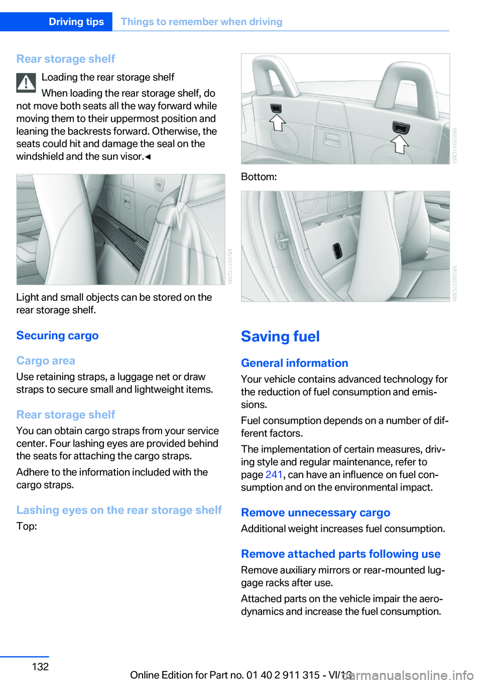
Rear storage shelfLoading the rear storage shelf
When loading the rear storage shelf, do
not move both seats all the way forward while moving them to their uppermost position and
leaning the backrests forward. Otherwise, the seats could hit and damage the seal on the
windshield and the sun visor.◀
Light and small objects can be stored on the
rear storage shelf.
Securing cargo
Cargo area
Use retaining straps, a luggage net or draw
straps to secure small and lightweight items.
Rear storage shelf You can obtain cargo straps from your service
center. Four lashing eyes are provided behind
the seats for attaching the cargo straps.
Adhere to the information included with the
cargo straps.
Lashing eyes on the rear storage shelf
Top:
Bottom:
Saving fuel
General information
Your vehicle contains advanced technology for
the reduction of fuel consumption and emis‐
sions.
Fuel consumption depends on a number of dif‐
ferent factors.
The implementation of certain measures, driv‐
ing style and regular maintenance, refer to
page 241, can have an influence on fuel con‐
sumption and on the environmental impact.
Remove unnecessary cargo
Additional weight increases fuel consumption.
Remove attached parts following use
Remove auxiliary mirrors or rear-mounted lug‐
gage racks after use.
Attached parts on the vehicle impair the aero‐
dynamics and increase the fuel consumption.
Seite 132Driving tipsThings to remember when driving132
Online Edition for Part no. 01 40 2 911 315 - VI/13
Page 134 of 285
Have maintenance carried outHave vehicles maintained regularly to achieve
optimal vehicle economy and operating life.
Have the maintenance carried out by your
service center.
Please also note the BMW Maintenance Sys‐
tem, refer to page 241.Seite 134Driving tipsThings to remember when driving134
Online Edition for Part no. 01 40 2 911 315 - VI/13