Page 81 of 289

3."Time:"4.Turn the controller until the desired hours
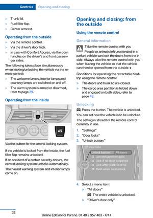
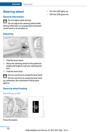
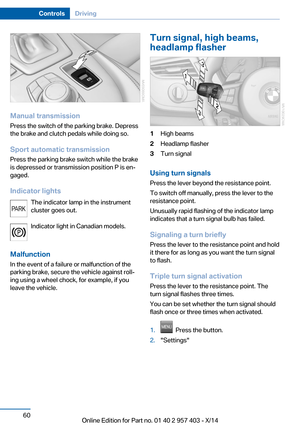
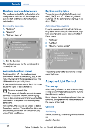
are displayed, and then press the control‐
ler.5.Turn the controller until the desired mi‐
nutes are displayed, and then press the
controller.
The time is stored.
Setting the time format
1."Settings"2."Time/Date"3."Format:"4.Select the desired format.
The time format is stored.
The settings are stored for the remote control
currently in use, Personal Profile, refer to
page 30.
Date
The settings are stored for the remote control
currently in use, Personal Profile, refer to
page 30.
Setting the date
In the instrument cluster To set the dd/mm or mm/dd date format, refer
to Setting the date format below.
1.Push button 1 in the turn indicator lever up
or down repeatedly until the appropriate
symbol appears in the display, accompa‐
nied by the date and the word "SET".2.Press button 2.3.Use button 1 to set the day of the month.4.Press button 2 to confirm the entry.5.Set the month and the year in the same
way.6.Press button 2.
The system stores the new date.
Via the iDrive
1."Settings"2."Time/Date"3."Date:"4.Turn the controller until the desired day is
displayed, and then press the controller.5.Make the necessary settings for the month
and year.
The date is stored.
Setting the date format
1."Settings"2."Time/Date"Seite 77DisplaysControls77
Online Edition for Part no. 01 40 2 957 403 - X/14
Page 82 of 289

3."Format:"4.Select the desired format.
The date format is stored.
Settings on the Control
Display
Language
Setting the language
To set the language on the Control Display:
1."Settings"2."Language/Units"3."Language:"4.Select the desired language.
The setting is stored for the remote control
currently in use.
Setting the voice dialog
Voice dialog for the voice activation system,
refer to page 26.
Brightness
Setting the brightness
To set the brightness of the Control Display:1."Settings"2."Control display"3."Brightness"4.Turn the controller until the desired bright‐
ness is set.5.Press the controller.
The setting is stored for the remote control
currently in use.
Depending on the light conditions, the bright‐
ness control may not be clearly visible.
Service requirements
Display
The remaining driving distance and the date of
the next maintenance are displayed briefly af‐
ter the ignition is switched on.
Seite 78ControlsDisplays78
Online Edition for Part no. 01 40 2 957 403 - X/14
Page 83 of 289
The current service requirements can be read
out from the remote control by the service
specialist.
Data regarding the maintenance status or le‐
gally mandated inspections of the vehicle are
automatically transmitted to your service cen‐
ter before a service due date, Automatic Serv‐
ice Request, refer to page 215.
The remaining driving distance or the due date
can be displayed individually for certain main‐
tenance procedures.1.Switch on the ignition.2.Press button 1 in the turn indicator lever up
or down repeatedly until the appropriate
symbol appears in the display, accompa‐
nied by the words "SERVICE INFO".3.Press button 2.4.Use button 1 to scroll through the individ‐
ual service items.Seite 79DisplaysControls79
Online Edition for Part no. 01 40 2 957 403 - X/14
Page 84 of 289
Possible displays1Button for selecting functions2Service requirements3Engine oil4Roadworthiness test5Front brake pads6Rear brake pads7Brake fluidThe sequence of displayed service items may
vary. The data for the next service appointment
is shown first.Seite 80ControlsDisplays80
Online Edition for Part no. 01 40 2 957 403 - X/14
Page 85 of 289
More information
Detailed information on service
requirements
More information on the scope of service re‐
quired can be displayed on the Control Dis‐
play.1."Vehicle Info"2."Vehicle status"3."Service required"
Required maintenance procedures and le‐
gally mandated inspections are displayed.4.Select an entry to call up detailed informa‐
tion.SymbolsSymbolsDescriptionNo service is currently re‐
quired.The deadline for service or a
legally mandated inspection is
approaching.The service deadline has al‐
ready passed.
Entering appointment dates
Enter the dates for the required inspections.
Ensure that the vehicle date and time are set
correctly on the Control Display.
1."Vehicle Info"2."Vehicle status"3."Service required"4."§ Vehicle inspection"5."Date:"Seite 81DisplaysControls81
Online Edition for Part no. 01 40 2 957 403 - X/14
Page 86 of 289

6.Create the settings.7.Confirm.
The entered date is stored.
Automatic Service Request
Data regarding the maintenance status or le‐
gally mandated inspections of the vehicle are
automatically transmitted to your service cen‐
ter before a service due date.
You can check when your service center was
notified.
1."Vehicle Info"2."Vehicle status"3.Open "Options".4."Last Service Request"
Check Control
The concept The Check Control monitors vehicle functions
and alerts you to any malfunctions in the sys‐
tems monitored.
Such Check Control messages involve indica‐
tor or warning lamps in the instrument cluster
and, in some circumstances, an acoustic signal
and text messages at the bottom of the Con‐
trol Display.
Indicator/warning lamps
The indicator and warning lamps can light up in
a variety of combinations and colors.
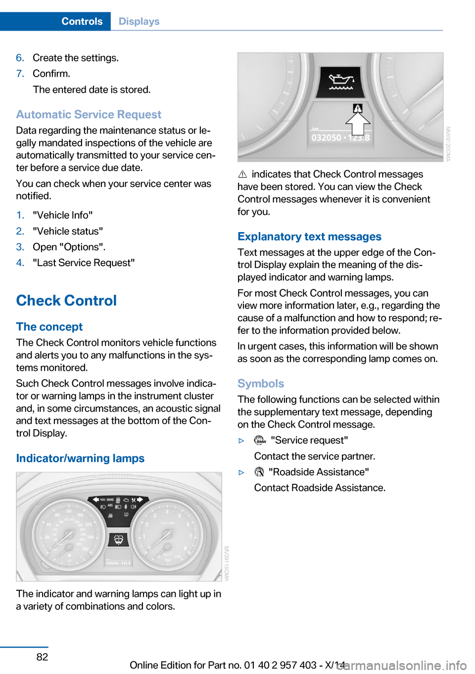
indicates that Check Control messages
have been stored. You can view the Check
Control messages whenever it is convenient
for you.
Explanatory text messages Text messages at the upper edge of the Con‐
trol Display explain the meaning of the dis‐
played indicator and warning lamps.
For most Check Control messages, you can
view more information later, e.g., regarding the
cause of a malfunction and how to respond; re‐
fer to the information provided below.
In urgent cases, this information will be shown
as soon as the corresponding lamp comes on.
Symbols
The following functions can be selected within
the supplementary text message, depending
on the Check Control message.
▷ "Service request"
Contact the service partner.▷ "Roadside Assistance"
Contact Roadside Assistance.Seite 82ControlsDisplays82
Online Edition for Part no. 01 40 2 957 403 - X/14
Page 87 of 289

Hiding Check Control messages
Press the button in the turn indicator lever.
Some Check Control messages are displayed
until the malfunctions have been rectified.
They cannot be hidden. If several malfunctions
occur at the same time, they are displayed in
succession.
They are marked with the symbol
shown here.
Other messages are automatically hidden after
approx. 20 seconds, but are kept in memory.
They are marked with the symbol
shown here.
Viewing stored Check Control
messages
1.Press button 1 in the turn indicator lever up
or down repeatedly until the appropriate
symbol appears in the display, accompa‐
nied by the words "CHECK CONTROL".2.Press button 2. If there is no Check Control
message, this is indicated by "CHECK
OK“.If a Check Control message has been
stored, the corresponding lamp comes on.
It is accompanied by a text message on the
Control Display.3.Press button 1 to check for other mes‐
sages.4.Press button 2.
The display again shows the external tem‐
perature and the time.
Displaying stored Check Control
messages
1. Press the button.2."Vehicle Info"3."Vehicle status"4."Check Control"5.Select the text message.
Messages after trip completion
Special messages that were displayed during a
trip are displayed again after the ignition is
switched off.
Speed limit
You can enter a speed, and a Check Control
message will indicate when you reach this
speed. This enables you to receive warnings if
you exceed a speed limit in an urban area, for
example. You are only warned of reaching this
Seite 83DisplaysControls83
Online Edition for Part no. 01 40 2 957 403 - X/14
Page 88 of 289
speed a second time if your vehicle speed falls
below it again by at least 3 mph/5 km/h.1."Settings"2."Speed"3."Warning at:"4.Turn the controller until the desired limit is
displayed.5.Press the controller.
The speed limit is stored.
Activating/deactivating the limit
1."Settings"2."Speed"3."Warning"4.Press the controller.
Applying your current speed as the
limit
1."Settings"2."Speed"3."Select current speed"4.Press the controller.
The system adopts your current speed as the
limit.
Seite 84ControlsDisplays84
Online Edition for Part no. 01 40 2 957 403 - X/14