2014 BMW 650I CONVERTIBLE trunk
[x] Cancel search: trunkPage 145 of 243
Switching on/off
Switching on automatically Select transmission position R with the engine
running.
The backup camera image is displayed if the
system was switched on via the iDrive.
Automatic deactivation during forward
travel
The system switches off when a certain driving
distance or speed is exceeded.
Switch the system back on if necessary.
Switching on/off manually Press the button.▷On: the LED lights up.▷Off: the LED goes out.
The PDC is shown on the Control Display.
Switching on the rearview camera via
the iDrive
With PDC activated or Top View switched on:
"Rear view camera"
The rearview camera image is displayed. The
setting is stored for the remote control cur‐
rently in use.
Display on the Control Display
Functional requirement
▷The rearview camera is switched on.▷The trunk lid is fully closed.
Activating the assistance functions
More than one assistance function can be ac‐
tive at the same time.
▷Parking aid lines
"Parking aid lines"
Pathway and turning circle lines are dis‐
played.▷Obstacle marking
"Obstacle marking"
Spatially-shaped markings are displayed.
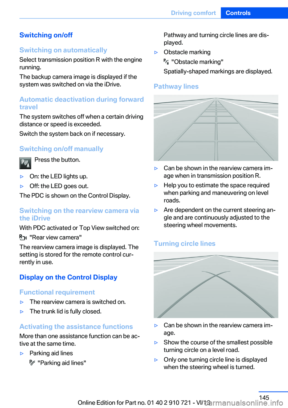
Pathway lines
▷Can be shown in the rearview camera im‐
age when in transmission position R.▷Help you to estimate the space required
when parking and maneuvering on level
roads.▷Are dependent on the current steering an‐
gle and are continuously adjusted to the
steering wheel movements.
Turning circle lines
▷Can be shown in the rearview camera im‐
age.▷Show the course of the smallest possible
turning circle on a level road.▷Only one turning circle line is displayed
when the steering wheel is turned.Seite 145Driving comfortControls145
Online Edition for Part no. 01 40 2 910 721 - VI/13
Page 148 of 243
The backup camera image is displayed. The
setting is stored for the remote control cur‐
rently in use.
Display
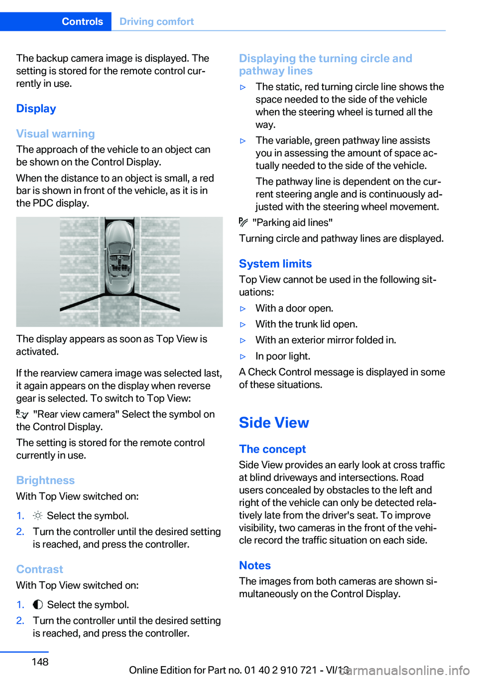
Visual warning The approach of the vehicle to an object can
be shown on the Control Display.
When the distance to an object is small, a red
bar is shown in front of the vehicle, as it is in
the PDC display.
The display appears as soon as Top View is
activated.
If the rearview camera image was selected last,
it again appears on the display when reverse
gear is selected. To switch to Top View:
"Rear view camera" Select the symbol on
the Control Display.
The setting is stored for the remote control
currently in use.
Brightness
With Top View switched on:
1. Select the symbol.2.Turn the controller until the desired setting
is reached, and press the controller.
Contrast
With Top View switched on:
1. Select the symbol.2.Turn the controller until the desired setting
is reached, and press the controller.Displaying the turning circle and
pathway lines▷The static, red turning circle line shows the
space needed to the side of the vehicle
when the steering wheel is turned all the
way.▷The variable, green pathway line assists
you in assessing the amount of space ac‐
tually needed to the side of the vehicle.
The pathway line is dependent on the cur‐
rent steering angle and is continuously ad‐
justed with the steering wheel movement.
"Parking aid lines"
Turning circle and pathway lines are displayed.
System limits
Top View cannot be used in the following sit‐
uations:
▷With a door open.▷With the trunk lid open.▷With an exterior mirror folded in.▷In poor light.
A Check Control message is displayed in some
of these situations.
Side View The concept Side View provides an early look at cross traffic
at blind driveways and intersections. Road
users concealed by obstacles to the left and
right of the vehicle can only be detected rela‐
tively late from the driver's seat. To improve
visibility, two cameras in the front of the vehi‐
cle record the traffic situation on each side.
Notes
The images from both cameras are shown si‐
multaneously on the Control Display.
Seite 148ControlsDriving comfort148
Online Edition for Part no. 01 40 2 910 721 - VI/13
Page 170 of 243
Without Professional navigation
system or TV: at a glance
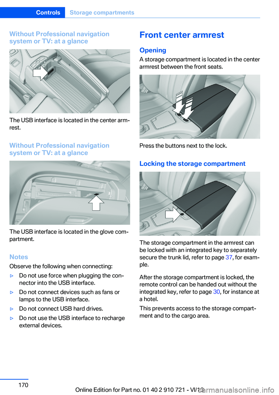
The USB interface is located in the center arm‐
rest.
Without Professional navigation
system or TV: at a glance
The USB interface is located in the glove com‐
partment.
Notes
Observe the following when connecting:
▷Do not use force when plugging the con‐
nector into the USB interface.▷Do not connect devices such as fans or
lamps to the USB interface.▷Do not connect USB hard drives.▷Do not use the USB interface to recharge
external devices.Front center armrest
Opening A storage compartment is located in the center
armrest between the front seats.
Press the buttons next to the lock.
Locking the storage compartment
The storage compartment in the armrest can
be locked with an integrated key to separately
secure the trunk lid, refer to page 37, for exam‐
ple.
After the storage compartment is locked, the
remote control can be handed out without the
integrated key, refer to page 30, for instance at
a hotel.
This prevents access to the storage compart‐
ment and to the cargo area.
Seite 170ControlsStorage compartments170
Online Edition for Part no. 01 40 2 910 721 - VI/13
Page 174 of 243
Things to remember when drivingVehicle equipment
All standard, country-specific and optional
equipment that is offered in the model series is
described in this chapter. Therefore, equip‐
ment is also described that is not available in a
vehicle, e. g., because of the selected optional
equipment or country variant. This also applies
for safety-related functions and systems.
Breaking-in period General information Moving parts need to be broken in to adjust to
each other.
The following instructions will help achieve a
long vehicle life and good economy.
Engine and differential Always obey the official speed limit.
Up to 1,200 miles/2,000 km
Do not exceed the maximum engine and road
speed:▷For gasoline engine 4,500 rpm and
100 mph/160 km/h.
Avoid full load or kickdown under all circum‐
stances.
From 1,200 miles/2,000 km The engine and vehicle speed can gradually be
increased.
Tires
Due to technical factors associated with their
manufacture, tires do not achieve their full
traction potential until after an initial breaking-
in period.
Drive conservatively for the first
200 miles/300 km.
Brake system
Brakes require an initial break-in period of ap‐
prox. 300 miles/500 km to achieve optimized
contact and wear patterns between brake
discs and brake pads. Drive moderately during
this break-in period.
Following part replacement
The same breaking in procedures should be
observed if any of the components mentioned
above have to be renewed in the course of the
vehicle's operating life.
General driving notes
Closing the trunk lid Drive with the trunk lid closed
Only drive with the tailgate closed; other‐
wise, in the event of an accident or braking and
evasive maneuvers, passengers and other road
users may be injured, and the vehicle may be
damaged. In addition, exhaust fumes may en‐
ter the passenger compartment.◀
If driving with the tailgate open cannot be
avoided:▷If the convertible top is closed, close all
windows.▷Greatly increase the blower speed.▷Drive moderately.
Hot exhaust system
Hot exhaust system
High temperatures are generated in the
exhaust system.
Do not remove the heat shields installed and
never apply undercoating to them. Make sure
that flammable materials, e. g. hay, leaves,
grass, etc. do not come in contact with the hot
Seite 174Driving tipsThings to remember when driving174
Online Edition for Part no. 01 40 2 910 721 - VI/13
Page 177 of 243
LoadingVehicle equipment
All standard, country-specific and optional
equipment that is offered in the model series is
described in this chapter. Therefore, equip‐
ment is also described that is not available in a
vehicle, e. g., because of the selected optional
equipment or country variant. This also applies
for safety-related functions and systems.
Hints Overloading the vehicle
To avoid exceeding the approved carry‐
ing capacity of the tires, never overload the ve‐
hicle. Overloading can lead to overheating and
increases the rate at which damage develops
inside the tires. This could result in a sudden
loss of tire inflation pressure.◀
No fluids in the trunk
Make sure that fluids do not leak into the
trunk; otherwise, the vehicle may be dam‐
aged.◀
Determining the load limit1.Locate the following statement on your ve‐
hicle’s placard:▷The combined weight of occupants
and cargo should never exceed XXX kg
or YYY lbs. Otherwise, damage to thevehicle and unstable driving situations
may result.2.Determine the combined weight of the
driver and passengers that will be riding in
your vehicle.3.Subtract the combined weight of the driver
and passengers from XXX kilograms or
YYY pounds.4.The resulting figure equals the available
amount of cargo and luggage load ca‐
pacity.
For example, if the YYY amount equals
1,000 lbs and there will be four 150 lbs
passengers in your vehicle, the amount of
available cargo and luggage load capacity
is 400 lbs: 1,000 lbs minus 600 lbs =
400 lbs.5.Determine the combined weight of lug‐
gage and cargo being loaded on the vehi‐
cle. That weight may not safely exceed the
available cargo and luggage load capacity
calculated in Step 4.
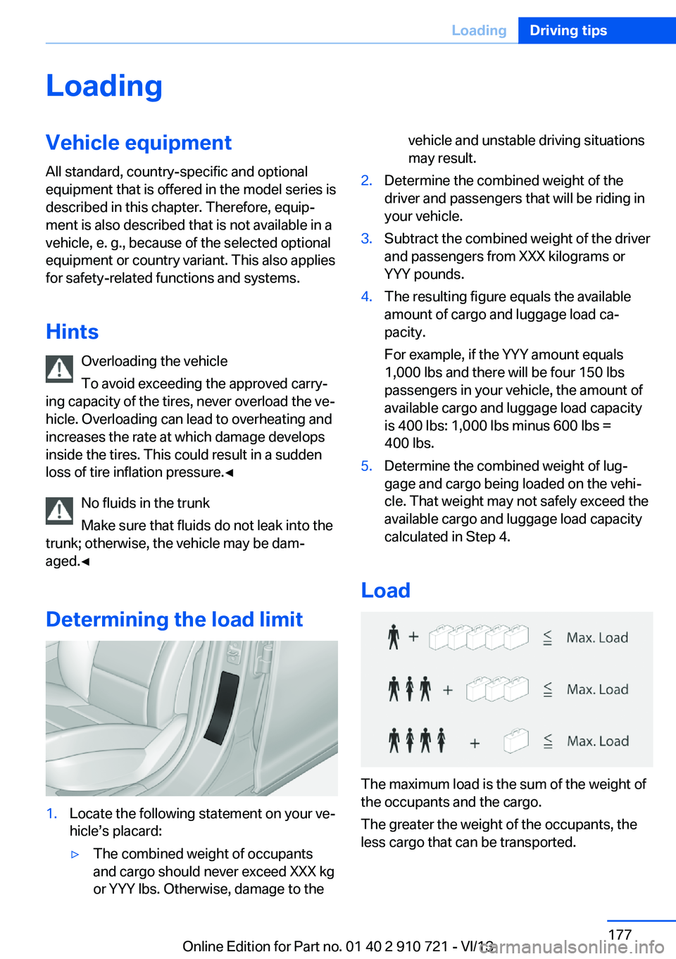
Load
The maximum load is the sum of the weight of
the occupants and the cargo.
The greater the weight of the occupants, the
less cargo that can be transported.
Seite 177LoadingDriving tips177
Online Edition for Part no. 01 40 2 910 721 - VI/13
Page 213 of 243

These lights feature LED technology.
Contact your service center in the event of a
malfunction.
Lamps in the trunk lidAccess to the lamps
If necessary, remove the fasteners using the
screwdriver from the onboard vehicle tool kit
and fold away the cover.
Inside brake lamp
Follow the general instructions on Lamps and
bulbs, refer to page 210.
24-watt bulb, HP24W
1.Squeeze the bulb holder and pull it out.2.Pull off the connector.3.Replace the bulb.4.Mount the bulb holder and the cover of the
trunk lid in reverse order.
Reversing lamp
Follow the general instructions on Lamps and
bulbs, refer to page 210.
16-watt bulb, W16W1.Unscrew the bulb holder counterclockwise.2.Pull out the bulb and replace it.3.Mount the bulb holder and the cover of the
trunk lid in reverse order.
Changing wheels
Hints
The vehicle equipment does not include a
spare tire.
When using run-flat tires or tire sealants, a tire
does not need to be changed immediately in
the event of pressure loss due to a flat tire.
The tools for changing wheels are available as
accessories from your service center.
Jacking points for the vehicle jack
The jacking points for the vehicle jack are lo‐
cated at the positions shown.
Seite 213Replacing componentsMobility213
Online Edition for Part no. 01 40 2 910 721 - VI/13
Page 235 of 243

Emergency unlocking, trunklid 38
Energy Control 84
Energy recovery 84
Engine, automatic Start/Stop function 65
Engine, automatic switch- off 65
Engine compartment 203
Engine compartment, work‐ ing in 203
Engine coolant 207
Engine idling when driving, coasting 183
Engine oil 205
Engine oil, adding 206
Engine oil additives 206
Engine oil change 206
Engine oil filler neck 206
Engine oil temperature 82
Engine oil types, alterna‐ tive 206
Engine oil types, ap‐ proved 206
Engine start during malfunc‐ tion 31
Engine start, jump-start‐ ing 218
Engine start, refer to Starting the engine 64
Engine stop 64
Engine temperature 82
Entering/exiting vehicle, as‐ sistance, steering wheel 59
Entering a car wash 221
Equipment, interior 164
ESP Electronic Stability Pro‐ gram, refer to DSC 122
Exchanging wheels/tires 199
Exhaust system 174
Exterior mirror, automatic dimming feature 58
Exterior mirrors 57
External start 218
External temperature dis‐ play 83 External temperature warn‐
ing 83
Eyes for securing cargo 178
F
Failure message, refer to Check Control 80
False alarm, refer to Uninten‐ tional alarm 41
Fan, refer to Air flow 158
Fault displays, refer to Check Control 80
Filler neck for engine oil 206
Fine wood, care 224
First aid kit 217
Fitting for towing, refer to Tow fitting 220
Flat tire, changing wheels 213
Flat Tire Monitor FTM 103
Flat tire, Tire Pressure Moni‐ tor TPM 100
Flat tire, warning lamp 101, 104
Flooding 175
Floor carpet, care 224
Floor mats, care 224
Fold-out position, windshield wipers 71
Foot brake 175
Front airbags 96
Front center armrest 170
Front fog lamps 94
Front lamps 210
Front passenger airbags, au‐ tomatic deactivation 98
Front passenger airbags, indi‐ cator lamp 98
Front seats 51
Front turn signals, refer to Light-emitting diodes,
LEDs 212
FTM Flat Tire Monitor 103
Fuel 190
Fuel cap 188 Fuel consumption, current 84
Fuel consumption, refer to Average fuel consump‐
tion 88
Fuel filler flap 188
Fuel gauge 82
Fuel quality 190
Fuel recommendation 190
Fuel, tank capacity 231
Fuse 214
G
Garage door opener, refer to Integrated universal remote
control 164
Gasoline 190
Gasoline quality 190
Gear change, automatic transmission 73
Gear shift indicator 85
General driving notes 174
Glove compartment 169
Gross vehicle weight, ap‐ proved 229
Gross weight, permissible for trailer towing 229
H
Handbrake, refer to Parking brake 67
Hand-held transmitter, alter‐ nating code 165
Hazard warning flashers 216
HDC Hill Descent Con‐ trol 124
Headlamp control, auto‐ matic 92
Headlamp courtesy delay fea‐ ture 91
Headlamp courtesy delay fea‐ ture via remote control 35
Headlamp flasher 70
Headlamp glass 211
Headlamps 210 Seite 235Everything from A to ZReference235
Online Edition for Part no. 01 40 2 910 721 - VI/13
Page 236 of 243

Headlamps, care 222
Headlamp washer system 70
Head restraints 51
Head restraints, front 55
Head-Up Display 154
Head-up Display, care 225
Heating, refer to Parked-car heating 161
Heavy cargo, stowing 178
Height, seats 51
Height, vehicle 228
High-beam Assistant 93
High beams 70
High beams/low beams, refer to High-beam Assistant 93
Hill Descent Control HDC 124
Hills 176
Hill start assistant, refer to Drive-off assistant 122
Hints 6
Holder for beverages 171
Homepage 6
Hood 203
Horn 12
Hotel function, trunk lid 37
Hot exhaust system 174
HUD Head-Up Display 154
Hydroplaning 175
I Ice warning, refer to External temperature warning 83
Icy roads, refer to External temperature warning 83
Identification marks, tires 197
Identification number, refer to Important features in the en‐
gine compartment 203
iDrive 16
Ignition key, refer to Remote control 30
Ignition off 63
Ignition on 63 Indication of a flat
tire 101 , 104
Indicator and warning lamps 80
Individual air distribution 158
Individual settings, refer to Personal Profile 31
Inflation pressure, tires 191
Inflation pressure warning FTM, tires 103
Info display, refer to Com‐ puter 87
Initialization, Integral Active Steering 126
Initialize, Tire Pressure Moni‐ tor TPM 101
Initializing, Flat Tire Monitor FTM 103
Instrument cluster 76
Instrument cluster, electronic displays 77
Instrument display, multifunc‐ tional 77
Instrument lighting 94
Integral Active Steering 125
Integrated key 30
Integrated universal remote control 164
Intelligent Emergency Re‐ quest 216
Intelligent Safety 105
Intensity, AUTO pro‐ gram 158
Interior equipment 164
Interior lamps 94
Interior lamps via remote con‐ trol 34
Interior motion sensor 41
Interior rearview mirror, auto‐ matic dimming feature 58
Internet page 6
Interval display, service re‐ quirements 84 J
Jacking points for the vehicle jack 213
Joystick, automatic transmis‐ sion 73
Jump-starting 218
K
Key/remote control 30
Keyless Go, refer to Comfort Access 38
Key Memory, refer to Per‐ sonal Profile 31
Kickdown, automatic trans‐ mission 73
Knee airbag 96
L Lamp replacement, front 210
Lamp replacement, rear 212
Lamps 91
Lamps and bulbs 210
Lane departure warning 116
Lane margin, warning 116
Language on Control Dis‐ play 90
Lashing eyes, securing cargo 178
LATCH child restraint fixing system 61
Leather, care 223
LED headlamps, Bulb re‐ placement 212
LED light 212
LEDs, light-emitting di‐ odes 211
Length, vehicle 229
Letters and numbers, enter‐ ing 21
License plate lamp, bulb re‐ placement 212
Light alloy wheels, care 224
Light control 92 Seite 236ReferenceEverything from A to Z236
Online Edition for Part no. 01 40 2 910 721 - VI/13