2014 BMW 640I GRAN COUPE Front center
[x] Cancel search: Front centerPage 30 of 243
Opening and closingVehicle equipment
All standard, country-specific and optional
equipment that is offered in the model series is
described in this chapter. Therefore, equip‐
ment is also described that is not available in a
vehicle, e. g., because of the selected optional
equipment or country variant. This also applies
for safety-related functions and systems.
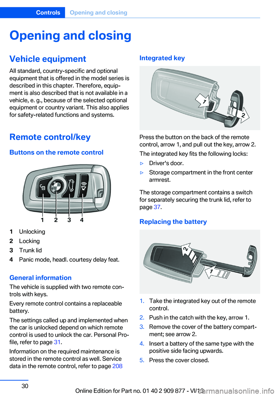
Remote control/key Buttons on the remote control1Unlocking2Locking3Trunk lid4Panic mode, headl. courtesy delay feat.
General information
The vehicle is supplied with two remote con‐
trols with keys.
Every remote control contains a replaceable
battery.
The settings called up and implemented when
the car is unlocked depend on which remote
control is used to unlock the car. Personal Pro‐
file, refer to page 31.
Information on the required maintenance is
stored in the remote control as well. Service
data in the remote control, refer to page 208
Integrated key
Press the button on the back of the remote
control, arrow 1, and pull out the key, arrow 2.
The integrated key fits the following locks:
▷Driver's door.▷Storage compartment in the front center
armrest.
The storage compartment contains a switch
for separately securing the trunk lid, refer to
page 37.
Replacing the battery
1.Take the integrated key out of the remote
control.2.Push in the catch with the key, arrow 1.3.Remove the cover of the battery compart‐
ment; see arrow 2.4.Insert a battery of the same type with the
positive side facing upwards.5.Press the cover closed.Seite 30ControlsOpening and closing30
Online Edition for Part no. 01 40 2 909 877 - VI/13
Page 37 of 243
Closing
Recessed grips in the interior trim of the trunk
lid make it easier to pull down the lid.
Keep the closing path clear
Make sure that the closing path of the
trunk lid is clear; otherwise, injuries may re‐
sult.◀
Do not place the remote control in the
cargo area
Take the remote control with you and do not
leave it in the cargo area; otherwise, the re‐
mote control is locked inside the vehicle when
the trunk lid is closed.◀
Locking the vehicle
Press the button on the inside of the trunk lid.
When the driver's door is closed, the vehicle is
completely locked.
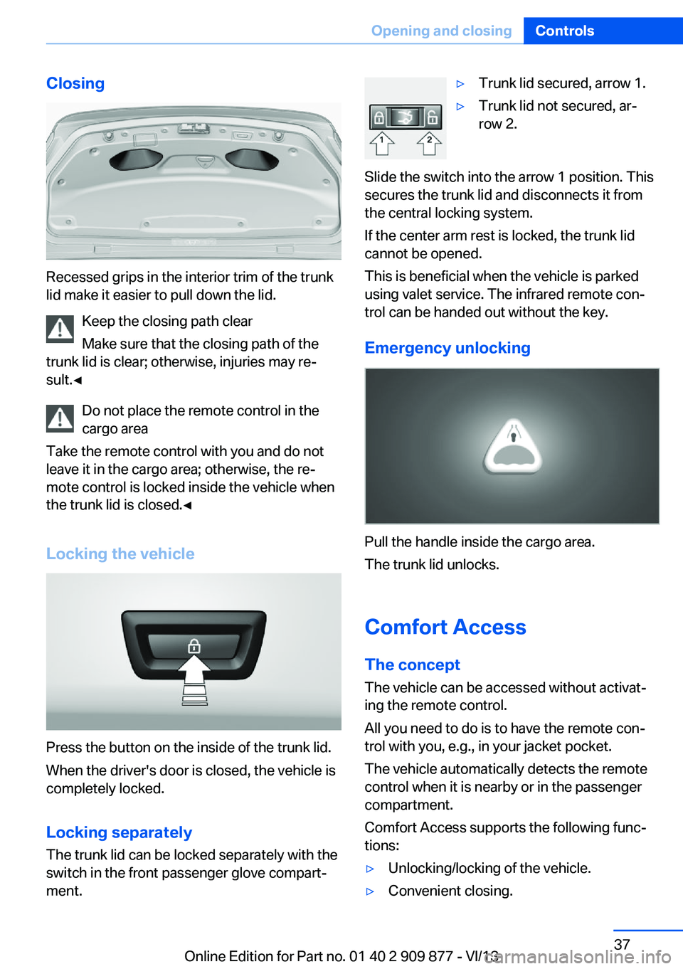
Locking separately The trunk lid can be locked separately with the
switch in the front passenger glove compart‐
ment.
▷Trunk lid secured, arrow 1.▷Trunk lid not secured, ar‐
row 2.
Slide the switch into the arrow 1 position. This
secures the trunk lid and disconnects it from
the central locking system.
If the center arm rest is locked, the trunk lid
cannot be opened.
This is beneficial when the vehicle is parked
using valet service. The infrared remote con‐
trol can be handed out without the key.
Emergency unlocking
Pull the handle inside the cargo area.
The trunk lid unlocks.
Comfort Access
The concept The vehicle can be accessed without activat‐
ing the remote control.
All you need to do is to have the remote con‐ trol with you, e.g., in your jacket pocket.
The vehicle automatically detects the remote
control when it is nearby or in the passenger
compartment.
Comfort Access supports the following func‐
tions:
▷Unlocking/locking of the vehicle.▷Convenient closing.Seite 37Opening and closingControls37
Online Edition for Part no. 01 40 2 909 877 - VI/13
Page 49 of 243
▷The center rear seat belt buckle is solely
intended for the center passenger.
One person per safety belt
Never allow more than one person to
wear a single safety belt. Never allow infants or
small children to ride on a passenger's lap.◀
Putting on the belt
Lay the belt, without twisting, snugly
across the lap and shoulders, as close to the
body as possible. Make sure that the belt lies
low around the hips in the lap area and does
not press on the abdomen. Otherwise, the belt
can slip over the hips in the lap area in a frontal
impact and injure the abdomen.
The safety belt must not lie across the neck,
rub on sharp edges, be routed over solid or
breakable objects, or be pinched.◀
Reduction of restraining effect
Avoid wearing clothing that prevents the
belt from fitting properly, and pull the shoulder
belt periodically to readjust the tension across
your lap; otherwise, the retention effect of the
safety belt may be reduced.◀
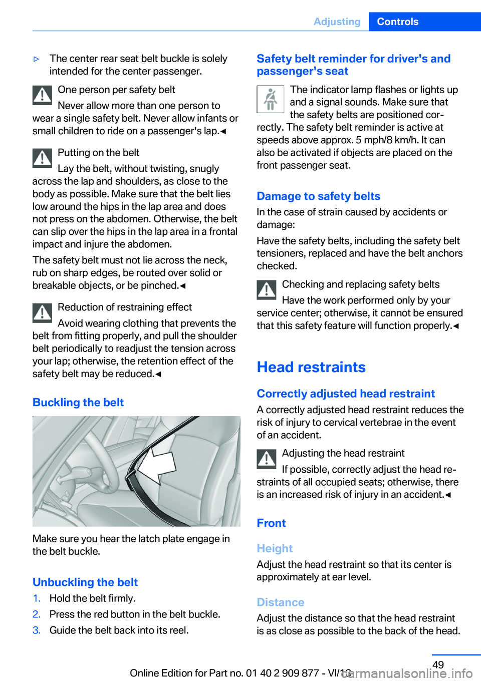
Buckling the belt
Make sure you hear the latch plate engage in
the belt buckle.
Unbuckling the belt
1.Hold the belt firmly.2.Press the red button in the belt buckle.3.Guide the belt back into its reel.Safety belt reminder for driver's and
passenger's seat
The indicator lamp flashes or lights up
and a signal sounds. Make sure that
the safety belts are positioned cor‐
rectly. The safety belt reminder is active at
speeds above approx. 5 mph/8 km/h. It can
also be activated if objects are placed on the
front passenger seat.
Damage to safety belts In the case of strain caused by accidents or
damage:
Have the safety belts, including the safety belt
tensioners, replaced and have the belt anchors checked.
Checking and replacing safety belts
Have the work performed only by your
service center; otherwise, it cannot be ensured
that this safety feature will function properly.◀
Head restraints
Correctly adjusted head restraint A correctly adjusted head restraint reduces the
risk of injury to cervical vertebrae in the event
of an accident.
Adjusting the head restraint
If possible, correctly adjust the head re‐
straints of all occupied seats; otherwise, there
is an increased risk of injury in an accident.◀
Front
Height
Adjust the head restraint so that its center is
approximately at ear level.
Distance
Adjust the distance so that the head restraint
is as close as possible to the back of the head.Seite 49AdjustingControls49
Online Edition for Part no. 01 40 2 909 877 - VI/13
Page 93 of 243
Protective action
Airbags are not triggered in every impact situa‐
tion, e.g., in less severe accidents or rear-end
collisions.
Information on how to ensure the optimal
protective effect of the airbags▷Keep at a distance from the airbags.▷Always grasp the steering wheel on the
steering wheel rim, holding your hands at
the 3 o'clock and 9 o'clock positions, to
keep the danger of injury to your hands or
arms as low as possible if the airbag is trig‐
gered.▷There should be no people, animals, or ob‐
jects between an airbag and a person.▷Do not use the cover of the front airbag on
the front passenger side as a storage area.▷Keep the dashboard and window on the
front passenger side clear, i.e., do not
cover with adhesive labels or coverings,
and do not attach holders such as for navi‐
gation instruments and mobile phones.▷Make sure that the front passenger is sit‐
ting correctly, i.e., keeps his or her feet and
legs in the footwell; otherwise, leg injuries
can occur if the front airbag is triggered.▷Do not place slip covers, seat cushions or
other objects on the front passenger seat
that are not approved specifically for seats
with integrated side airbags.▷Do not hang pieces of clothing, such as
jackets, over the backrests.▷Make sure that occupants keep their heads
away from the side airbag and do not rest
against the head airbag; otherwise, injuries
can occur if the airbags are triggered.▷Do not remove the airbag restraint system.▷Do not remove the steering wheel.▷Do not apply adhesive materials to the air‐
bag cover panels, cover them or modify
them in any way.▷Never modify either the individual compo‐
nents or the wiring in the airbag system.
This also applies to steering wheel covers,
the dashboard, the seats, the roof pillars
and the sides of the headliner.◀
Even when all instructions are followed closely,
injury from contact with the airbags cannot be
ruled out in certain situations.
The ignition and inflation noise may lead to
short-term and, in most cases, temporary
hearing impairment in sensitive individuals.
In the case of a malfunction, deactivation
and after triggering of the airbags
Do not touch the individual components imme‐
diately after the system has been triggered;
otherwise, there is the danger of burns.
Only have the airbags checked, repaired or dis‐
mantled and the airbag generator scrapped by
your service center or a workshop that has the
necessary authorization for handling explo‐
sives.
Non-professional attempts to service the sys‐
tem could lead to failure in an emergency or
undesired triggering of the airbag, either of
which could result in injury.◀
Warnings and information on the airbags are
also found on the sun visors.
Functional readiness of the airbag
system
When the ignition is switch on, the
warning lamp in the instrument cluster
lights up briefly and thereby indicates
the operational readiness of the entire airbag
system and the belt tensioner.
Airbag system malfunctioning
▷Warning lamp does not come on when the
ignition is turned on.▷The warning lamp lights up continuously.Seite 93SafetyControls93
Online Edition for Part no. 01 40 2 909 877 - VI/13
Page 150 of 243
Adjusting the height1."Settings"2."Head-Up Display"3."Height"4.Turn the controller.
The setting is stored for the remote control
currently in use.
Setting the rotation
1."Settings"2."Head-Up Display"3."Rotation"4.Turn the controller.
The setting is stored for the remote control
currently in use.
Special windshield
The windshield is part of the system.
The shape of the windshield makes it possible
to display a precise image.
A film in the windshield prevents double im‐
ages from being displayed.
Therefore, have the special windshield re‐
placed by a service center only.
Distance information The conceptThe system displays a symbol in the Head-up
Display to indicate that the distance behind the
vehicle in front is not sufficient.
General information The distance is determined by the radar sen‐
sor of the Active Cruise Control.
Hints
Personal responsibility
The display does not relieve the driver of
the responsibility to adapt his or her distance
and driving style to the traffic conditions. Main‐
tain the prescribed safety distance.◀
At a glance
Radar sensor
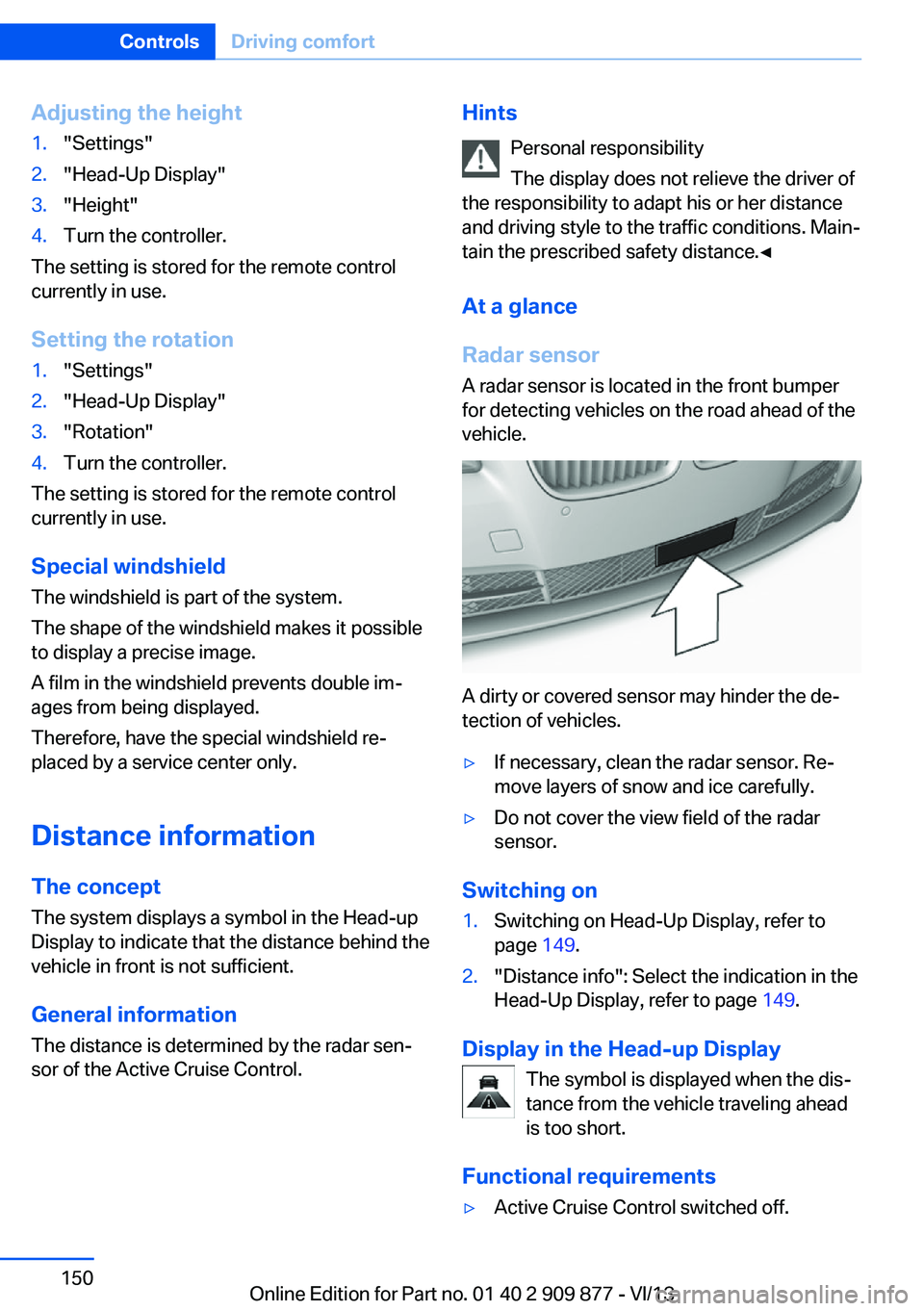
A radar sensor is located in the front bumper
for detecting vehicles on the road ahead of the
vehicle.
A dirty or covered sensor may hinder the de‐
tection of vehicles.
▷If necessary, clean the radar sensor. Re‐
move layers of snow and ice carefully.▷Do not cover the view field of the radar
sensor.
Switching on
1.Switching on Head-Up Display, refer to
page 149.2."Distance info": Select the indication in the
Head-Up Display, refer to page 149.
Display in the Head-up Display
The symbol is displayed when the dis‐
tance from the vehicle traveling ahead
is too short.
Functional requirements
▷Active Cruise Control switched off.Seite 150ControlsDriving comfort150
Online Edition for Part no. 01 40 2 909 877 - VI/13
Page 157 of 243
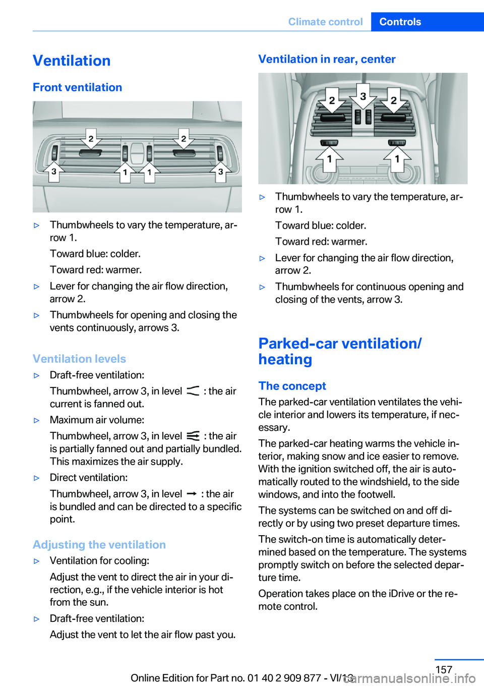
VentilationFront ventilation▷Thumbwheels to vary the temperature, ar‐
row 1.
Toward blue: colder.
Toward red: warmer.▷Lever for changing the air flow direction,
arrow 2.▷Thumbwheels for opening and closing the
vents continuously, arrows 3.
Ventilation levels
▷Draft-free ventilation:
Thumbwheel, arrow 3, in level
: the air
current is fanned out.
▷Maximum air volume:
Thumbwheel, arrow 3, in level
: the air
is partially fanned out and partially bundled.
This maximizes the air supply.
▷Direct ventilation:
Thumbwheel, arrow 3, in level
: the air
is bundled and can be directed to a specific
point.
Adjusting the ventilation
▷Ventilation for cooling:
Adjust the vent to direct the air in your di‐
rection, e.g., if the vehicle interior is hot
from the sun.▷Draft-free ventilation:
Adjust the vent to let the air flow past you.Ventilation in rear, center▷Thumbwheels to vary the temperature, ar‐
row 1.
Toward blue: colder.
Toward red: warmer.▷Lever for changing the air flow direction,
arrow 2.▷Thumbwheels for continuous opening and
closing of the vents, arrow 3.
Parked-car ventilation/
heating
The concept The parked-car ventilation ventilates the vehi‐
cle interior and lowers its temperature, if nec‐
essary.
The parked-car heating warms the vehicle in‐
terior, making snow and ice easier to remove.
With the ignition switched off, the air is auto‐
matically routed to the windshield, to the side
windows, and into the footwell.
The systems can be switched on and off di‐
rectly or by using two preset departure times.
The switch-on time is automatically deter‐
mined based on the temperature. The systems
promptly switch on before the selected depar‐
ture time.
Operation takes place on the iDrive or the re‐ mote control.
Seite 157Climate controlControls157
Online Edition for Part no. 01 40 2 909 877 - VI/13
Page 163 of 243
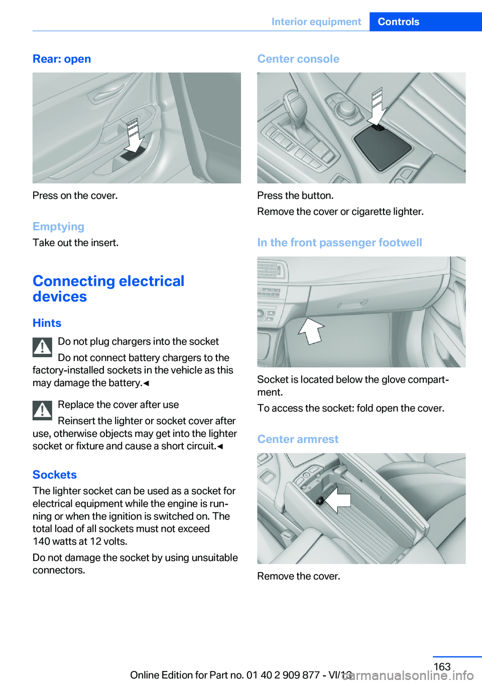
Rear: open
Press on the cover.
Emptying Take out the insert.
Connecting electrical devices
Hints Do not plug chargers into the socket
Do not connect battery chargers to the
factory-installed sockets in the vehicle as this
may damage the battery.◀
Replace the cover after use
Reinsert the lighter or socket cover after
use, otherwise objects may get into the lighter
socket or fixture and cause a short circuit.◀
Sockets
The lighter socket can be used as a socket for
electrical equipment while the engine is run‐
ning or when the ignition is switched on. The
total load of all sockets must not exceed
140 watts at 12 volts.
Do not damage the socket by using unsuitable
connectors.
Center console
Press the button.
Remove the cover or cigarette lighter.
In the front passenger footwell
Socket is located below the glove compart‐
ment.
To access the socket: fold open the cover.
Center armrest
Remove the cover.
Seite 163Interior equipmentControls163
Online Edition for Part no. 01 40 2 909 877 - VI/13
Page 167 of 243
Storage compartmentsVehicle equipmentAll standard, country-specific and optional
equipment that is offered in the model series is
described in this chapter. Therefore, equip‐
ment is also described that is not available in a
vehicle, e. g., because of the selected optional
equipment or country variant. This also applies
for safety-related functions and systems.
Notes No loose objects in the passenger com‐
partment
Do not stow any objects in the passenger
compartment without securing them; other‐
wise, they may present a danger to occupants
for instance during braking and avoidance ma‐
neuvers.◀
Do not place anti-slip mats on the dash‐
board
Do not place anti-slip mats on the dashboard.
The mat materials could damage the dash‐
board.◀
Storage compartments
The following storage compartments are avail‐
able in the vehicle interior:▷Glove compartment on the front passenger
side, refer to page 167.▷Storage compartment in the front center
armrest, refer to page 168.▷Storage compartment in the rear center
armrest, refer to page 169.▷Compartments in the doors.▷Pockets on the backrests of the front
seats.▷Net in the front passenger footwell.Glove compartment
Note Close the glove compartment again im‐
mediately
Close the glove compartment immediately af‐
ter use while driving; otherwise, injury may oc‐
cur during accidents.◀
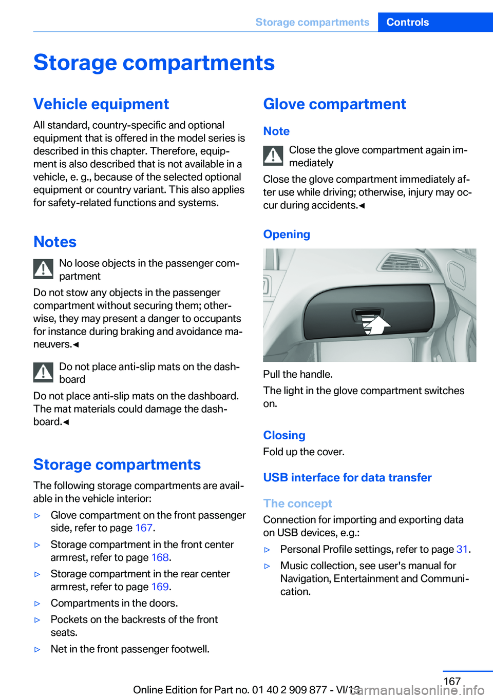
Opening
Pull the handle.
The light in the glove compartment switches
on.
ClosingFold up the cover.
USB interface for data transfer
The concept Connection for importing and exporting data
on USB devices, e.g.:
▷Personal Profile settings, refer to page 31.▷Music collection, see user's manual for
Navigation, Entertainment and Communi‐
cation.Seite 167Storage compartmentsControls167
Online Edition for Part no. 01 40 2 909 877 - VI/13