2014 BMW 6 SERIES COUPE lights
[x] Cancel search: lightsPage 155 of 247

Cameras
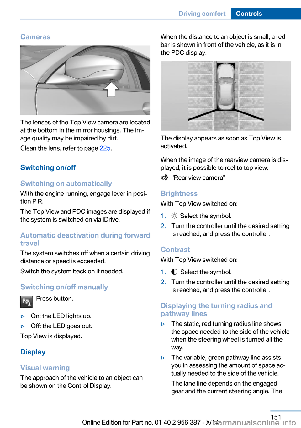
The lenses of the Top View camera are located
at the bottom in the mirror housings. The im‐
age quality may be impaired by dirt.
Clean the lens, refer to page 225.
Switching on/off
Switching on automatically With the engine running, engage lever in posi‐
tion P R.
The Top View and PDC images are displayed if
the system is switched on via iDrive.
Automatic deactivation during forward
travel
The system switches off when a certain driving
distance or speed is exceeded.
Switch the system back on if needed.
Switching on/off manually Press button.
▷On: the LED lights up.▷Off: the LED goes out.
Top View is displayed.
Display
Visual warning
The approach of the vehicle to an object can
be shown on the Control Display.
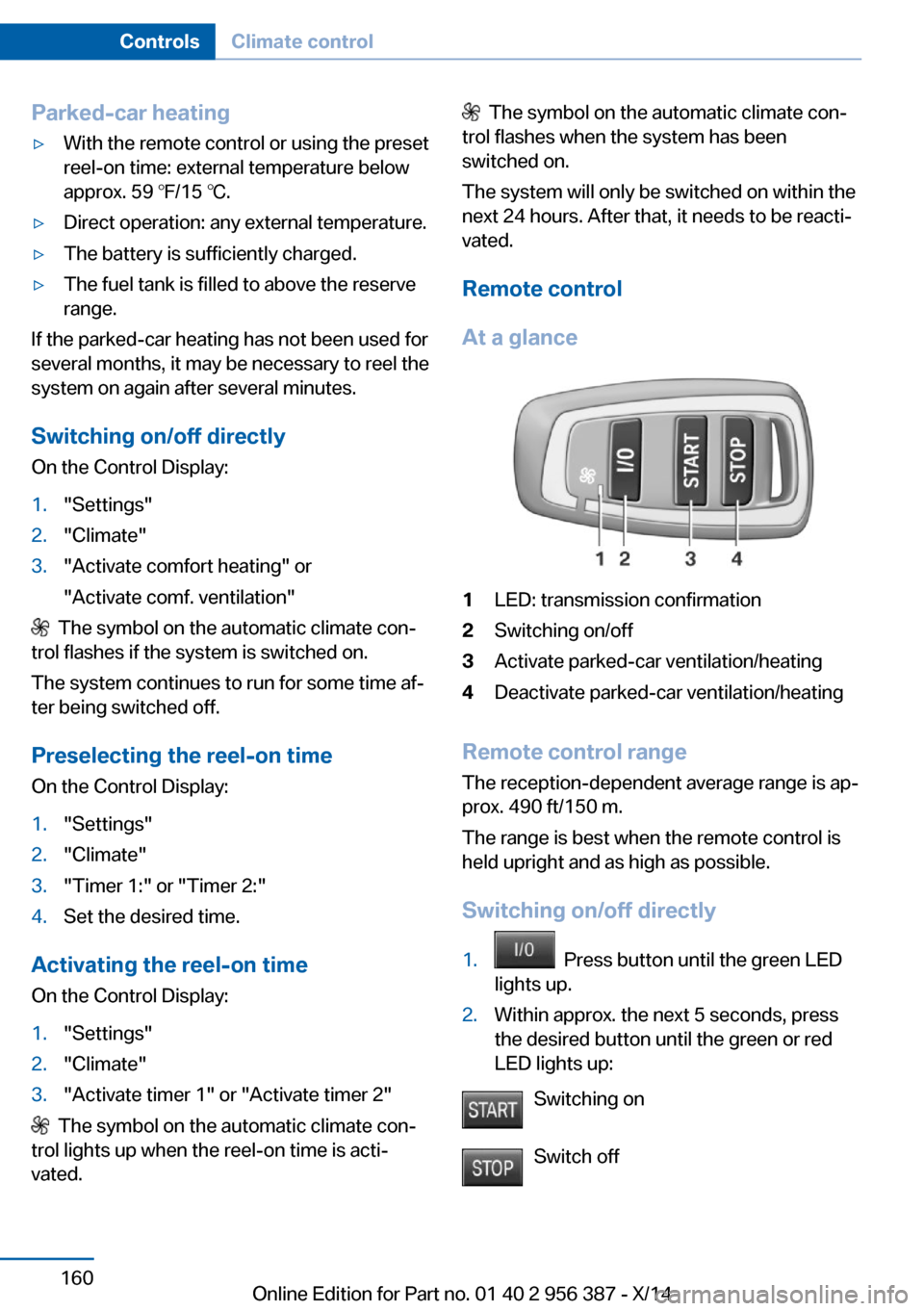
When the distance to an object is small, a red
bar is shown in front of the vehicle, as it is in
the PDC display.
The display appears as soon as Top View is
activated.
When the image of the rearview camera is dis‐
played, it is possible to reel to top view:
"Rear view camera"
Brightness
With Top View switched on:
1. Select the symbol.2.Turn the controller until the desired setting
is reached, and press the controller.
Contrast
With Top View switched on:
1. Select the symbol.2.Turn the controller until the desired setting
is reached, and press the controller.
Displaying the turning radius and
pathway lines
▷The static, red turning radius line shows
the space needed to the side of the vehicle
when the steering wheel is turned all the
way.▷The variable, green pathway line assists
you in assessing the amount of space ac‐
tually needed to the side of the vehicle.
The lane line depends on the engaged
gear and the current steering angle. TheSeite 151Driving comfortControls151
Online Edition for Part no. 01 40 2 956 387 - X/14
Page 157 of 247

▷Maximum distance to row of parked vehi‐
cles: 5 ft/1.5 m.
Suitable parking space
▷Gap between two objects with a minimum
length of approx. 5 ft/1.5 m.▷Min. length of gap between two objects:
your vehicle's length plus approx.
4 ft/1.2 m.▷Minimum depth: approx. 5 ft/1.5 m.
Regarding the parking procedure
▷Doors and trunk lid closed.▷Parking brake released.▷When parking in parking spaces on the
driver's side, the corresponding turn signal
must be set where applicable.
At a glance
Button in the vehicle
Parking assistant
Ultrasound sensors
The ultrasound sensors for measuring parking
spaces are located on the side of the vehicle.
To ensure full functionality:
▷Keep the sensors clean and free of ice.▷When using high-pressure washers, do not
spray the sensors for long periods and
maintain a distance of at least 12 in/30 cm.▷Do not put stickers over sensors.
Switching on/off
Switching on with the button Press button.
The LED lights up.
The current status of the parking space search
is indicated on the Control Display.
Parking assistant is activated automatically.
Switching on with the reverse gear
Shift into reverse.
The current status of the parking space search
is indicated on the Control Display.
To activate:
"Parking Assistant"
Switch off
The system can be deactivated as follows:
▷Press button.▷Switch off the ignition.Seite 153Driving comfortControls153
Online Edition for Part no. 01 40 2 956 387 - X/14
Page 164 of 247

Parked-car heating▷With the remote control or using the preset
reel-on time: external temperature below
approx. 59 ℉/15 ℃.▷Direct operation: any external temperature.▷The battery is sufficiently charged.▷The fuel tank is filled to above the reserve
range.
If the parked-car heating has not been used for
several months, it may be necessary to reel the
system on again after several minutes.
Switching on/off directly
On the Control Display:
1."Settings"2."Climate"3."Activate comfort heating" or
"Activate comf. ventilation"
The symbol on the automatic climate con‐
trol flashes if the system is switched on.
The system continues to run for some time af‐
ter being switched off.
Preselecting the reel-on time On the Control Display:
1."Settings"2."Climate"3."Timer 1:" or "Timer 2:"4.Set the desired time.
Activating the reel-on time
On the Control Display:
1."Settings"2."Climate"3."Activate timer 1" or "Activate timer 2"
The symbol on the automatic climate con‐
trol lights up when the reel-on time is acti‐
vated.
The symbol on the automatic climate con‐
trol flashes when the system has been
switched on.
The system will only be switched on within the
next 24 hours. After that, it needs to be reacti‐
vated.
Remote control
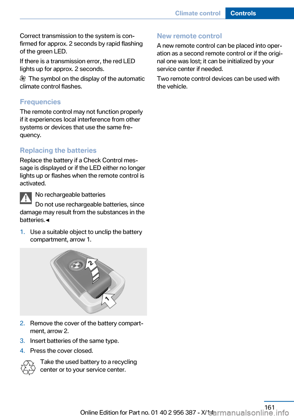
At a glance1LED: transmission confirmation2Switching on/off3Activate parked-car ventilation/heating4Deactivate parked-car ventilation/heating
Remote control range The reception-dependent average range is ap‐
prox. 490 ft/150 m.
The range is best when the remote control is
held upright and as high as possible.
Switching on/off directly
1. Press button until the green LED
lights up.2.Within approx. the next 5 seconds, press
the desired button until the green or red
LED lights up:
Switching on
Switch off
Seite 160ControlsClimate control160
Online Edition for Part no. 01 40 2 956 387 - X/14
Page 165 of 247

Correct transmission to the system is con‐
firmed for approx. 2 seconds by rapid flashing
of the green LED.
If there is a transmission error, the red LED
lights up for approx. 2 seconds.
The symbol on the display of the automatic
climate control flashes.
Frequencies The remote control may not function properly
if it experiences local interference from other
systems or devices that use the same fre‐
quency.
Replacing the batteries Replace the battery if a Check Control mes‐
sage is displayed or if the LED either no longer
lights up or flashes when the remote control is
activated.
No rechargeable batteries
Do not use rechargeable batteries, since
damage may result from the substances in the
batteries.◀
1.Use a suitable object to unclip the battery
compartment, arrow 1.2.Remove the cover of the battery compart‐
ment, arrow 2.3.Insert batteries of the same type.4.Press the cover closed.
Take the used battery to a recycling
center or to your service center.
New remote control
A new remote control can be placed into oper‐
ation as a second remote control or if the origi‐
nal one was lost; it can be initialized by your
service center if needed.
Two remote control devices can be used with
the vehicle.Seite 161Climate controlControls161
Online Edition for Part no. 01 40 2 956 387 - X/14
Page 172 of 247

▷Do not use force when plugging the con‐
nector into the USB interface.▷Do not connect devices such as fans or
lights to the USB interface.▷Do not connect USB hard drives.▷Do not use the USB interface for recharg‐
ing external devices.
With navigation system Professional
or TV: at a glance
The USB interface is located in the center arm‐
rest.
Front center armrest Opening
A storage compartment is located in the center
armrest between the front seats.
Press buttons next to the lock.
Locking the storage compartment
The storage compartment in the armrest can
be locked with an integrated key to separately
secure the trunk lid, refer to page 40, e.g.
After the storage compartment is locked, the
remote control can be handed out without the
integrated key, refer to page 34, for instance at
a hotel.
This prevents access to the storage compart‐
ment and to the cargo area.
Connection for an external audio
device
An external audio device, e.g.,
an MP3 player, can be con‐
nected via the AUX-IN port or
the USB audio interface in the center armrest.
Clothes hooks Do not obstruct view
When suspending clothing from the
hooks, ensure that it will not obstruct the driv‐
er's view.◀
No heavy objects
Do not hang heavy objects from the
hooks; otherwise, they may present a danger
to passengers during braking and evasive ma‐
neuvers.◀
Seite 168ControlsStorage compartments168
Online Edition for Part no. 01 40 2 956 387 - X/14
Page 182 of 247

accelerating, shift up before reaching high en‐
gine speeds.
When you reach the desired speed, shift into
the highest applicable gear and drive with the
engine speed as low as possible and at a con‐
stant speed.
If necessary, observe the gear shift indicator of
the vehicle, refer to page 87.
Use coasting When approaching a red light, take your foot
off the accelerator and let the vehicle coast to
a halt.
For going downhill take your foot off the accel‐
erator and let the vehicle roll.
The flow of fuel is interrupted while coasting.
Switch off the engine during
longer stops
Switch off the engine during longer stops, e.g.,
at traffic lights, railroad crossings or in traffic
congestion.
Auto Start/Stop function The Auto Start/Stop function of your vehicle
automatically switches off the engine during a
stop.
If the engine is switched off and then restarted
rather than leaving the engine running con‐
stantly, fuel consumption and emissions are
reduced. Savings can begin within a few sec‐
onds of switching off the engine.
In addition, fuel consumption is also deter‐
mined by other factors, such as driving style,
road conditions, maintenance or environmental
factors.Switch off any functions that
are not currently needed
Functions such as seat heating and the rear
window defroster require a lot of energy and
reduce the range, especially in city and stop-
and-go traffic.
Reel off these functions if they are not needed.
The ECO PRO driving program supports the
energy conserving use of comfort features.
These functions are automatically deactivated
partially or completely.
Have maintenance carried
out
Have vehicles maintained regularly to achieve
optimal vehicle efficiency and operating life.
The maintenance should be carried out by
your service center.
Also note the BMW Maintenance System, refer
to page 209.
ECO PRO
The concept
ECO PRO supports a driving style that saves
on fuel consumption. For this purpose, the en‐
gine control and comfort features, e. g. the cli‐
mate control output, are adjusted.
Under certain conditions the engine is auto‐
matically decoupled from the transmission in
the D selector lever position. The vehicle con‐
tinues traveling with the engine idling to re‐
duce fuel consumption. Selector lever position
D remains engaged.
In addition, context-sensitive instructions are
displayed to assist with an optimized fuel con‐
sumption driving style.
The achieved extended range is displayed in
the instrument cluster as bonus range.Seite 178Driving tipsSaving fuel178
Online Edition for Part no. 01 40 2 956 387 - X/14
Page 214 of 247

correspondingly trained personnel and other
authorized persons. Otherwise, use may result
in operating problems for the vehicle.◀
Position
There is an OBD socket on the driver's side for
checking the primary components in the vehi‐
cle's emissions.
Emissions
▷The warning lamp lights up:
Emissions are deteriorating. Have
the vehicle checked as soon as
possible.▷The warning lamp flashes under certain
circumstances:
This indicates that there is excessive mis‐
firing in the engine.
Reduce the vehicle speed and have the
system checked immediately; otherwise,
serious engine misfiring within a brief pe‐
riod can seriously damage emission con‐
trol components, in particular the catalytic
converter.Seite 210MobilityMaintenance210
Online Edition for Part no. 01 40 2 956 387 - X/14
Page 215 of 247

Replacing componentsVehicle features and optionsThis chapter describes all standard, country-
specific and optional features offered with the
series. It also describes features that are not
necessarily available in your car, e. g., due to
the selected options or country versions. This
also applies to safety-related functions and
systems.
Onboard vehicle tool kit
The onboard vehicle tool kit is located under
the cargo floor panel.
Wiper blade replacement General information Do not fold down the wipers without
wiper blades
Do not fold down the wipers if wiper blades
have not been installed; this may damage the
windshield.◀
Replacing the wiper blades1.To change the wiper blades, fold up, refer
to page 70, the wiper arms.2.Fold up the wipers.3.Position the wiper blade in a horizontal po‐
sition.4.Remove the wiper blade toward one side.5.Insert the new wiper blade in reverse order
of removal until it locks in place.6.Fold down the wipers.
Lamp and bulb replacement
Hints
Lights and bulbs
Lights and bulbs make an essential contribu‐
tion to vehicle safety.
The manufacturer of the vehicle recommends
that you entrust corresponding procedures to
Seite 211Replacing componentsMobility211
Online Edition for Part no. 01 40 2 956 387 - X/14