2014 BMW 5 SERIES GRAN TURISMO socket
[x] Cancel search: socketPage 93 of 259
Flashing: the conditions are not adequate for
operating the system.
The system was deactivated but applies the
brakes until you actively resume control by
pressing on the brake pedal or accelerator
pedal.
Yellow lights
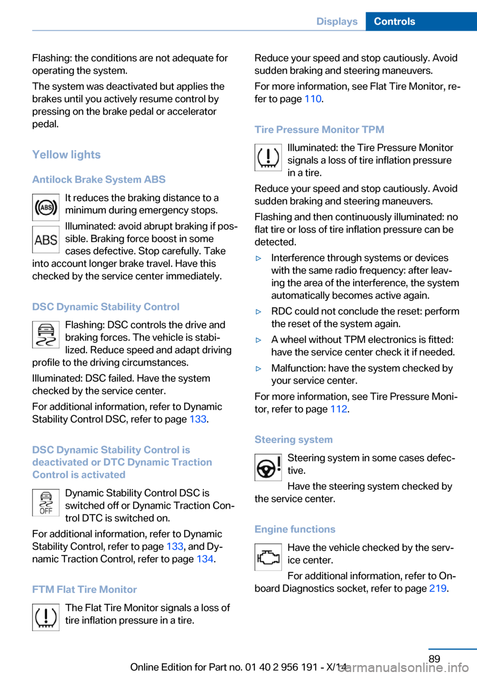
Antilock Brake System ABS It reduces the braking distance to a
minimum during emergency stops.
Illuminated: avoid abrupt braking if pos‐
sible. Braking force boost in some
cases defective. Stop carefully. Take
into account longer brake travel. Have this
checked by the service center immediately.
DSC Dynamic Stability Control Flashing: DSC controls the drive and
braking forces. The vehicle is stabi‐
lized. Reduce speed and adapt driving
profile to the driving circumstances.
Illuminated: DSC failed. Have the system
checked by the service center.
For additional information, refer to Dynamic
Stability Control DSC, refer to page 133.
DSC Dynamic Stability Control is
deactivated or DTC Dynamic Traction
Control is activated
Dynamic Stability Control DSC is
switched off or Dynamic Traction Con‐
trol DTC is switched on.
For additional information, refer to Dynamic
Stability Control, refer to page 133, and Dy‐
namic Traction Control, refer to page 134.
FTM Flat Tire Monitor The Flat Tire Monitor signals a loss of
tire inflation pressure in a tire.Reduce your speed and stop cautiously. Avoid
sudden braking and steering maneuvers.
For more information, see Flat Tire Monitor, re‐
fer to page 110.
Tire Pressure Monitor TPM Illuminated: the Tire Pressure Monitor
signals a loss of tire inflation pressure
in a tire.
Reduce your speed and stop cautiously. Avoid
sudden braking and steering maneuvers.
Flashing and then continuously illuminated: no
flat tire or loss of tire inflation pressure can be
detected.▷Interference through systems or devices
with the same radio frequency: after leav‐
ing the area of the interference, the system
automatically becomes active again.▷RDC could not conclude the reset: perform
the reset of the system again.▷A wheel without TPM electronics is fitted:
have the service center check it if needed.▷Malfunction: have the system checked by
your service center.
For more information, see Tire Pressure Moni‐
tor, refer to page 112.
Steering system Steering system in some cases defec‐
tive.
Have the steering system checked by
the service center.
Engine functions Have the vehicle checked by the serv‐ice center.
For additional information, refer to On-
board Diagnostics socket, refer to page 219.
Seite 89DisplaysControls89
Online Edition for Part no. 01 40 2 956 191 - X/14
Page 176 of 259
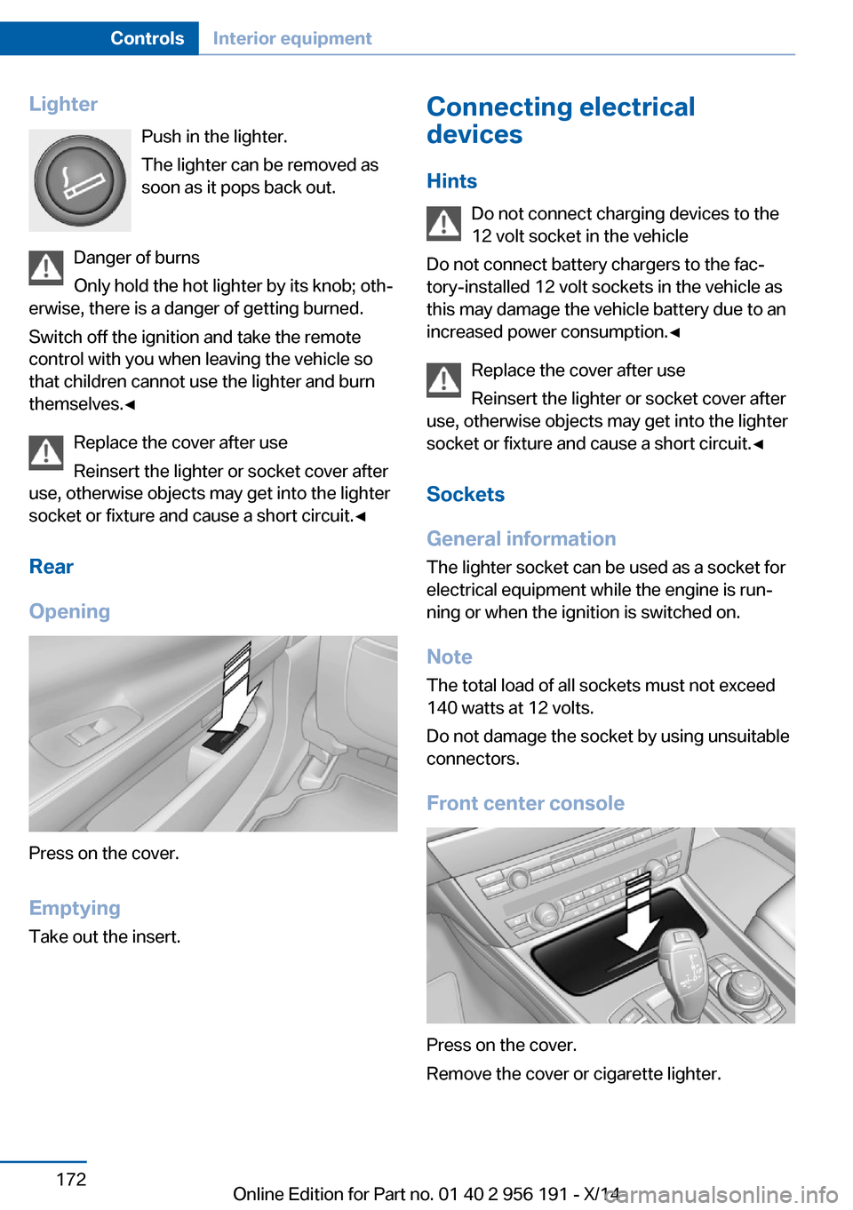
LighterPush in the lighter.
The lighter can be removed as
soon as it pops back out.
Danger of burns
Only hold the hot lighter by its knob; oth‐
erwise, there is a danger of getting burned.
Switch off the ignition and take the remote
control with you when leaving the vehicle so
that children cannot use the lighter and burn
themselves.◀
Replace the cover after use
Reinsert the lighter or socket cover after
use, otherwise objects may get into the lighter
socket or fixture and cause a short circuit.◀
Rear
Opening
Press on the cover.
Emptying Take out the insert.
Connecting electrical
devices
Hints Do not connect charging devices to the
12 volt socket in the vehicle
Do not connect battery chargers to the fac‐
tory-installed 12 volt sockets in the vehicle as
this may damage the vehicle battery due to an
increased power consumption.◀
Replace the cover after use
Reinsert the lighter or socket cover after
use, otherwise objects may get into the lighter
socket or fixture and cause a short circuit.◀
Sockets
General information
The lighter socket can be used as a socket for
electrical equipment while the engine is run‐
ning or when the ignition is switched on.
NoteThe total load of all sockets must not exceed140 watts at 12 volts.
Do not damage the socket by using unsuitable
connectors.
Front center console
Press on the cover.
Remove the cover or cigarette lighter.
Seite 172ControlsInterior equipment172
Online Edition for Part no. 01 40 2 956 191 - X/14
Page 177 of 259
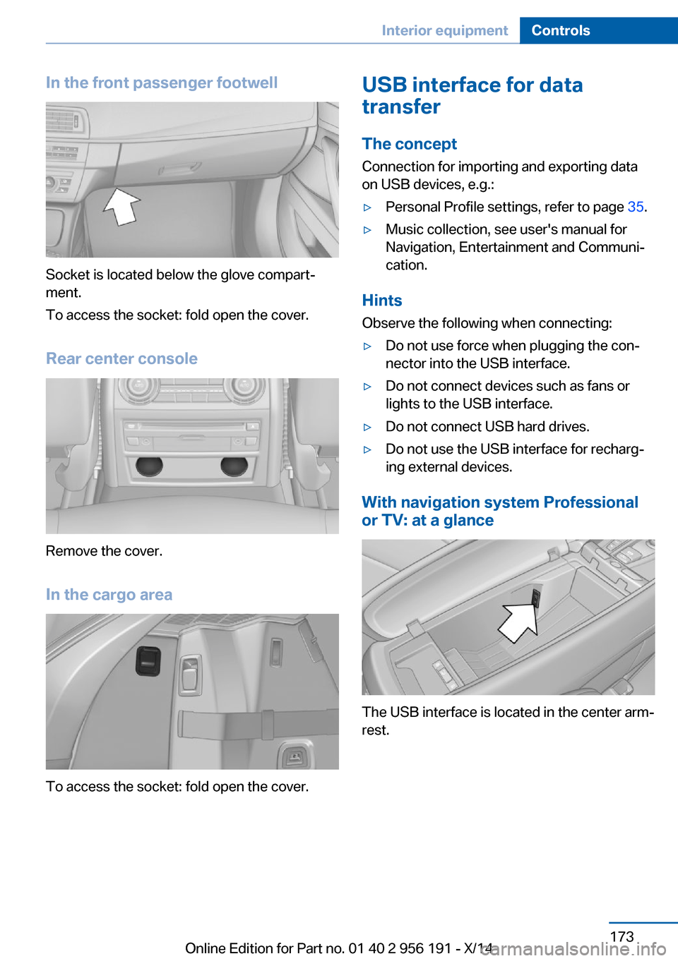
In the front passenger footwell
Socket is located below the glove compart‐
ment.
To access the socket: fold open the cover.
Rear center console
Remove the cover.
In the cargo area
To access the socket: fold open the cover.
USB interface for data
transfer
The concept Connection for importing and exporting data
on USB devices, e.g.:▷Personal Profile settings, refer to page 35.▷Music collection, see user's manual for
Navigation, Entertainment and Communi‐
cation.
Hints
Observe the following when connecting:
▷Do not use force when plugging the con‐
nector into the USB interface.▷Do not connect devices such as fans or
lights to the USB interface.▷Do not connect USB hard drives.▷Do not use the USB interface for recharg‐
ing external devices.
With navigation system Professional
or TV: at a glance
The USB interface is located in the center arm‐
rest.
Seite 173Interior equipmentControls173
Online Edition for Part no. 01 40 2 956 191 - X/14
Page 223 of 259

MaintenanceVehicle features and options
This chapter describes all standard, country-
specific and optional features offered with the
series. It also describes features that are not
necessarily available in your car, e. g., due to
the selected options or country versions. This
also applies to safety-related functions and
systems.
BMW maintenance system
The maintenance system indicates required
maintenance measures, and thereby provides
support in maintaining road safety and the op‐
erational reliability of the vehicle.
Condition Based Service
CBS
Sensors and special algorithms take into ac‐
count the driving conditions of your vehicle.
Based on this, Condition Based Service recog‐
nizes the maintenance requirements.
The system makes it possible to adapt the
amount of maintenance corresponding to your
user profile.
Details on the service requirements, refer to
page 93, can be displayed on the Control Dis‐
play.
Service data in the remote control Information on the required maintenance is
continuously stored in the remote control.
Your service center will read out this data and
suggest the right array of service procedures
for your vehicle.
Therefore, hand your service specialist the re‐
mote control with which the vehicle was driven
most recently.Storage periods
Storage periods during which the vehicle bat‐
tery was disconnected are not taken into ac‐
count.
If this occurs, have a service center update the
time-dependent maintenance procedures,
such as checking brake fluid and, if needed,
changing the engine oil and the microfilter/
activated-charcoal filter.
Service and Warranty
Information Booklet for US
models and Warranty and
Service Guide Booklet for
Canadian models
Please consult your Service and Warranty In‐
formation Booklet for US models and Warranty
and Service Guide Booklet for Canadian mod‐ els for additional information on service re‐
quirements.
Maintenance and repair should be performed
by your service center. Make sure to have reg‐
ular maintenance procedures recorded in the
vehicle's Service and Warranty Information
Booklet for US models, and in the Warranty
and Service Guide Booklet for Canadian mod‐
els. These entries are proof of regular mainte‐
nance.
Socket for OBD Onboard
Diagnosis
Note Socket for Onboard Diagnosis
The socket for onboard diagnostics may
only be used by the service center or a work‐
shop that operates in accordance with the
specifications of the vehicle manufacturer withSeite 219MaintenanceMobility219
Online Edition for Part no. 01 40 2 956 191 - X/14
Page 224 of 259
correspondingly trained personnel and other
authorized persons. Otherwise, use may result
in operating problems for the vehicle.◀
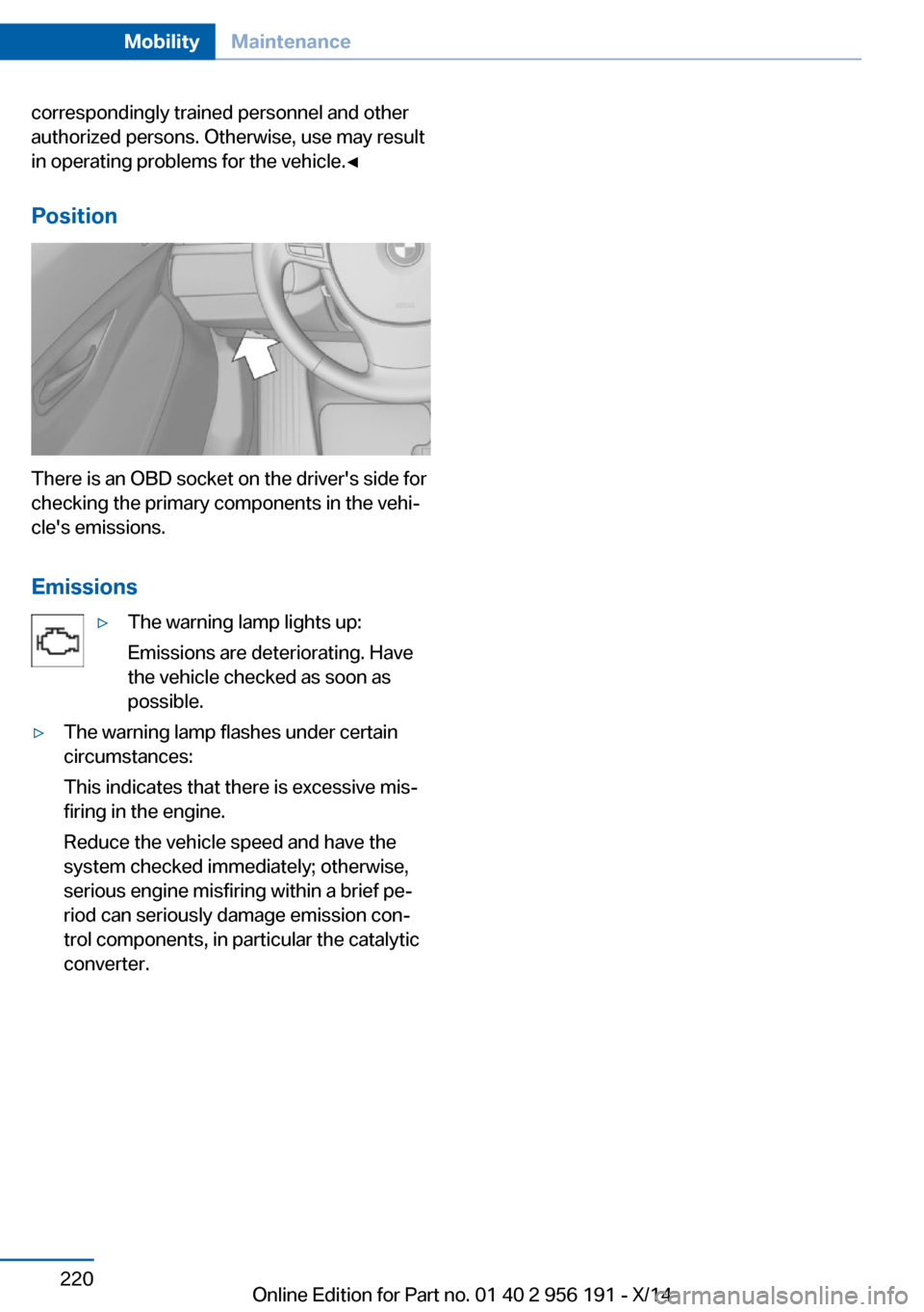
Position
There is an OBD socket on the driver's side for
checking the primary components in the vehi‐
cle's emissions.
Emissions
▷The warning lamp lights up:
Emissions are deteriorating. Have
the vehicle checked as soon as
possible.▷The warning lamp flashes under certain
circumstances:
This indicates that there is excessive mis‐
firing in the engine.
Reduce the vehicle speed and have the
system checked immediately; otherwise,
serious engine misfiring within a brief pe‐
riod can seriously damage emission con‐
trol components, in particular the catalytic
converter.Seite 220MobilityMaintenance220
Online Edition for Part no. 01 40 2 956 191 - X/14
Page 230 of 259
Further information about the battery can be
obtained from your service center.
Battery replacement Use approved vehicle batteries only
Only use vehicle batteries that have been
approved for your vehicle by the manufacturer;
otherwise, the vehicle could be damaged and
systems or functions may not be fully availa‐
ble.◀
After a battery replacement, have the battery
registered on the vehicle by your service cen‐
ter to ensure that all comfort features are fully
available and that any Check Control mes‐
sages of these comfort features are no longer
displayed.
Charging the battery
Note Do not connect charging devices to the
12 volt socket in the vehicle
Do not connect battery chargers to the fac‐
tory-installed 12 volt sockets in the vehicle as
this may damage the vehicle battery due to an
increased power consumption.◀
General information
Make sure that the battery is always suffi‐
ciently charged to guarantee that the battery
remains usable for its full service life.
The battery may need to be charged in the fol‐
lowing cases:▷When making frequent short-distance
drives.▷If the vehicle is not used for prolonged pe‐
riods, longer than a month.
Starting aid terminals
In the vehicle, only charge the battery via the
starting aid terminals, refer to page 230, in the
engine compartment with the engine off.
Power failure
After a temporary power loss, some equipment
needs to be newly initialized or individual set‐
tings updated, e.g.:▷Seat, mirror, and steering wheel memory:
store the positions again.▷Time: update.▷Date: update.▷Glass sunroof: initialize the system, refer to
page 52.
Disposing of old batteries
Have old batteries disposed of by your
service center or bring them to a recy‐
cling center.
Maintain the battery in an upright position for
transport and storage. Secure the battery so
that it does not tip over during transport.
Fuses Hints Replacing fuses
Never attempt to repair a blown fuse and
do not replace a defective fuse with a substi‐
tute of another color or amperage rating; this
could lead to a circuit overload, ultimately re‐
sulting in a fire in the vehicle.◀
Plastic tweezers and information on the fuse
types and locations are stored in the fuse box
in the cargo area.
Seite 226MobilityReplacing components226
Online Edition for Part no. 01 40 2 956 191 - X/14
Page 254 of 259

Obstacle marking, rearviewcamera 154
Octane rating, refer to Rec‐ ommended fuel grade 200
Odometer 92
Office, see user's manual for Navigation, Entertainment
and Communication
Oil 214
Oil, adding 215
Oil additives 215
Oil change 216
Oil change interval, service requirements 93
Oil filler neck 215
Oil types, alternative 216
Oil types, approved 216
Old batteries, disposal 226
Onboard monitor, refer to Control Display 18
Onboard vehicle tool kit 221
Opening/closing via door lock 39
Opening and closing 34
Opening and closing, without remote control 39
Opening and closing, with re‐ mote control 37
Opening the tailgate with no- touch activation 45
Operating concept, iDrive 18
Optional equipment, standard equipment 6
Outside air, refer to Auto‐ matic recirculated-air con‐
trol 164
Overheating of engine, refer to Coolant temperature 92
P Paint, vehicle 234
Panoramic glass sunroof 51
Parallel parking assistant 158
Park Distance Control PDC 150 Parked-car ventilation 168
Parked vehicle, condensa‐ tion 186
Parking aid, refer to PDC 150
Parking assistant 158
Parking brake 73
Parking lights 102
Parking with Automatic Hold 74
Passenger side mirror, tilting downward 63
Pathway lines, rearview cam‐ era 153
PDC Park Distance Con‐ trol 150
Pedestrian detection, see Night Vision 124
Pedestrian warning with city braking function 122
Personal Profile 35
Personal Profile, exporting profiles 36
Pinch protection system, glass sunroof 52
Pinch protection system, win‐ dows 49
Plastic, care 235
Power failure 226
Power windows 49
Pressure, tire air pres‐ sure 202
Pressure warning FTM, tires 110
Profile, refer to Personal Pro‐ file 35
Programmable memory but‐ tons, iDrive 23
Protective function, glass sunroof 52
Protective function, win‐ dows 49
Push-and-turn reel, refer to Controller 18 R
Radiator fluid 217
Radio-operated key, refer to Remote control 34
Radio ready state 70
Radio, see user's manual for Navigation, Entertainment
and Communication
Rain sensor 79
Rear automatic climate con‐ trol 166
Rear axle steering 137
Rear lights 224
Rear seats 57
Rear sockets 173
Rearview camera 152
Rearview mirror 62
Rear window defroster 164
Recirculated-air mode 164
Recommended fuel grade 200
Recommended tire brands 208
Refueling 198
Remaining range 92
Remote control/key 34
Remote control, malfunc‐ tion 39
Remote control, univer‐ sal 169
Replacement fuse 226
Replacing parts 221
Replacing wheels/tires 208
Reporting safety defects 9
RES button 144
RES button, see Active Cruise Control, ACC 141
RES button, see Cruise con‐ trol 148
Reserve warning, refer to Range 92
Reset, Tire Pressure Monitor TPM 113
Residual heat, automatic cli‐ mate control 165 Seite 250ReferenceEverything from A to Z250
Online Edition for Part no. 01 40 2 956 191 - X/14
Page 255 of 259

Retaining straps, securingcargo 188
Retreaded tires 209
Reversing lamp, bulb replace‐ ment 224
Roadside parking lights 103
Roller sunblinds 50
Roll stabilization, refer to Adaptive Drive 136
Roll stabilization, refer to Dy‐ namic Drive 136
RON recommended fuel grade 200
Roofliner 17
Roof load capacity 241
Roof-mounted luggage rack 188
Rope for tow-starting/ towing 231
RSC Run Flat System Com‐ ponent, refer to Run-flat
tires 209
Rubber components, care 235
Run-flat tires 209
S Safe braking 185
Safety 7
Safety belt reminder for driv‐ er's seat and front passen‐
ger seat 59
Safety belts 58
Safety belts, care 235
Safety Package, refer to Ac‐ tive Protection 131
Safety reel, windows 50
Safety systems, airbags 107
Saving fuel 190
Screen, refer to Control Dis‐ play 18
Screwdriver, see Onboard ve‐ hicle tool kit 221 Screw thread, see screw
thread for tow fitting, screw
thread for tow fitting 232
Seat belts, refer to Safety belts 58
Seat heating, front 56
Seat heating, rear 57
Seating position for chil‐ dren 65
Seat, mirror, and steering wheel memory 61
Seats 53
Seats, front 53
Seats, rear 57
Seat ventilation, front 56
Selection list in instrument cluster 96
Selector lever, Steptronic transmission 81
Self-leveling suspension, air suspension 138
Self-leveling suspension, malfunction 138
Sensors, care 236
Service and warranty 8
Service requirements, Condi‐ tion Based Service
CBS 219
Service requirements, dis‐ play 93
Service, Roadside Assis‐ tance 229
Services, ConnectedDrive
SET button, see Active Cruise Control, ACC 141
SET button, see Cruise con‐ trol 148
Settings, locking/unlock‐ ing 46
Settings on Control Dis‐ play 98
Settings, storing for seat, mir‐ rors, steering wheel 61
Shift paddles on steering wheel 82
Shoulder support 56 Side airbags 107
Side View 155
Signaling, horn 14
Signals when unlocking 47
Sitting safely 53
Size 240
Ski and snowboard bag 176
Slide/tilt glass roof 51
Smallest turning radius 240
Small tailgate via remote con‐ trol 38
Smoker's package 171
Snow chains 210
Socket 172
Socket, OBD Onboard Diag‐ nostics 219
SOS button 228
Spare fuse 226
Speaker lighting 106
Specified engine oil types 216
Speed, average 97
Speed limit detection, com‐ puter 97
Speed limiter, display 94
Speed Limit Information 94
Speed warning 98
Split screen 23
SPORT+ - program, Dynamic Driving Control 139
Sport displays, torque dis‐ play, performance dis‐
play 98
SPORT program, driving dy‐ namics 139
Sport program, transmis‐ sion 82
Stability control systems 133
Start/stop, automatic func‐ tion 71
Start/Stop button 70
Start function during malfunc‐ tion 35
Starting the engine 71
Status control display, tires 112 Seite 251Everything from A to ZReference251
Online Edition for Part no. 01 40 2 956 191 - X/14