2014 BMW 5 SERIES GRAN TURISMO change wheel
[x] Cancel search: change wheelPage 7 of 259
Addendum
read in its place. In addition, the
text of that section should be
disregarded and the following text
should be read in lieu thereof:
The manufacturer of your vehicle
strongly suggests that you use
wheels and tires that have been
recommended by the vehicle
manufacturer for your vehicle type;
otherwise, for example, despite
having the same official size ratings,
variations can lead to body contact
and with it, the risk of severe
accidents.
The manufacturer of your vehicle
does not evaluate non-
recommended wheels and tires to
determine if they are suitable for
use on your vehicle.
14.At page 210, under the heading:
“Fine-link snow chains,” the text
should be disregarded and the
following text should be read in lieu
thereof:
Only certain types of fine-link snow
chains have been tested by the
manufacturer of your vehicle and
are determined by the manufacturer
of your vehicle to be road safe and
are recommended by the
manufacturer of your vehicle.
Information about recommended
snow chains is available from a
service center.
15.At page 212, under the heading
“Hood,” the sentence beginning, “If
you are unfamiliar” should be
disregarded.
16.At page 216, under the heading:
“Approved oil types,” the references
to “Approved” should be read as
“Suitable.” Where it reads: You
can add oils with the following
specifications,” that text should be
disregarded, and the following text
read in lieu thereof: “Add engine
oils that meet the following oil rating
standards: . . .”
17.At page 216, under the heading:
“Alternative oil types,” the text
preceding the chart should be
disregarded, and in lieu thereof
should be read as follows: “If an
engine oil suitable for continuous
use is not available, up to 1 US
quart/liter of an engine oil with the
following oil rating can be
added: . . .” The reference to
“specification” should be read as
“rating.”
18.At page 216, under the heading:
“Engine oil change,” the text should
be disregarded and in lieu thereof
should be read as follows:
BMW recommends that you have
the oil changed at your BMW
dealer’s service center or at another
service center that has trained
personnel that can perform the work
in accordance with BMW
specifications.
19.At page 219, under the heading:
“Service and Warranty Information
Booklet for US models and
Warranty and Service Guide
Booklet for Canadian models,” the
second paragraph should be
Page 31 of 259
Executing functions using short
commands
Execute functions on the main menu via short
commands. It almost doesn't matter which
menu item is selected, e.g., ›Vehicle status‹.
List of short commands for the voice activation
system, see Navigation, Entertainment, Com‐
munication Owner's Manual.
Help dialog for the voice activation
system
Calling up help dialog: ›Help‹
Additional commands for the help dialog:▷›Help with examples‹: announces informa‐
tion about the current operating options
and the most important commands for
them.▷›Help with voice activation‹: information
about the principle of operation for the
voice activation system is announced.
One example: open the tone
settings
Via the main menu The commands of the menu items are spoken
just as they are selected via the controller.
1.Turn on the Entertainment sound output if
needed.2. Press button on the steering
wheel.3.›Radio‹4.›Tone‹
Via short command
The desired tone settings can also be started
via a short command.
1.Turn on the Entertainment sound output if
needed.2. Press button on the steering
wheel.3.›Tone‹
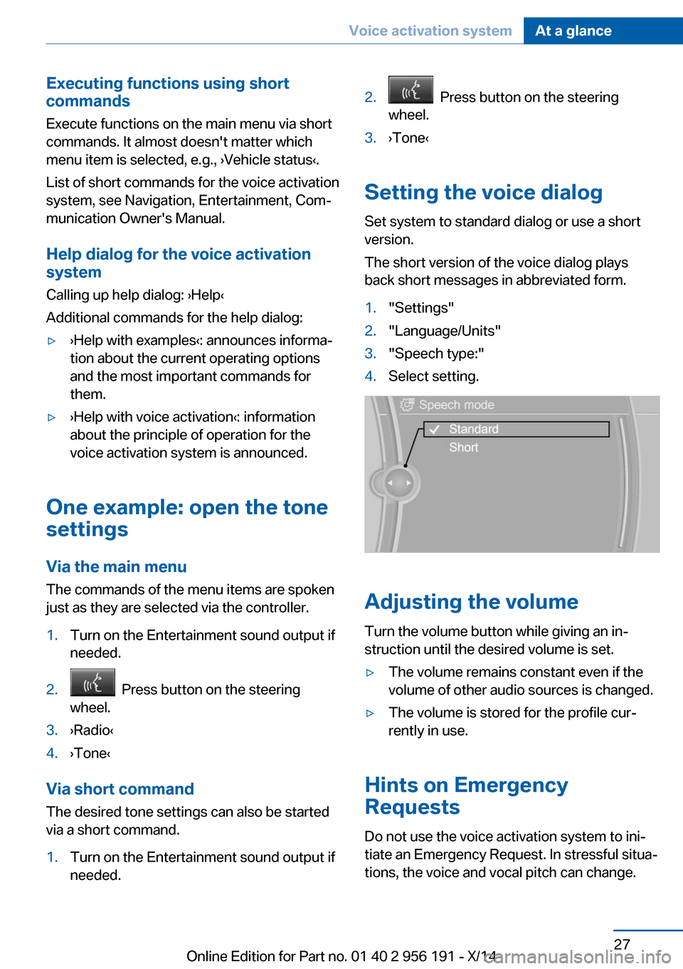
Setting the voice dialog
Set system to standard dialog or use a short
version.
The short version of the voice dialog plays
back short messages in abbreviated form.
1."Settings"2."Language/Units"3."Speech type:"4.Select setting.
Adjusting the volume
Turn the volume button while giving an in‐
struction until the desired volume is set.
▷The volume remains constant even if the
volume of other audio sources is changed.▷The volume is stored for the profile cur‐
rently in use.
Hints on Emergency
Requests
Do not use the voice activation system to ini‐
tiate an Emergency Request. In stressful situa‐
tions, the voice and vocal pitch can change.
Seite 27Voice activation systemAt a glance27
Online Edition for Part no. 01 40 2 956 191 - X/14
Page 51 of 259
The large tailgate is opened and the
doors unlocked.▷"Small tailgate"
The small tailgate is unlocked.▷"Small tailgate section + door(s)"
The small tailgate and the doors are
unlocked.
Confirmation signals from the vehicle
The settings are saved in the active profile, re‐
fer to page 35.
1."Settings"2."Doors/key"3.Deactivate or activate the desired confir‐
mation signals.▷"Acoustic sig. lock/unlock"▷"Flash when lock/unlock"
Automatic locking
The settings are saved in the active profile, re‐fer to page 35.
1."Settings"2."Doors/key"3.Select the desired function:▷"Lock if no door is opened"
The vehicle locks automatically after a
short period of time if no door is
opened.▷"Lock after start driving"
The vehicle locks automatically after
you drive off.
Headlight courtesy delay feature
The settings are saved in the active profile, re‐
fer to page 35.
1."Settings"2."Doors/key"3. Select the symbol.4."Pathway lighting"Retrieving the seat, mirror, and
steering wheel settings
The driver's seat, exterior mirror, and steering
wheel position adjusted last will be stored for
the active profile.
When the vehicle is unlocked, these positions
are automatically retrieved if this function was
activated.
Pinch hazard when moving back the seat
If this function is used, first make sure
that the footwell behind the driver's seat is
empty. Otherwise, people might get injured or
objects damaged when the seat is moved
back.◀
The adjustment procedure is interrupted:▷When a seat position reel is pressed.▷When a button of the seat, mirror, and
steering wheel memory is pressed briefly.
Activating the setting
1."Settings"2."Doors/key"3."Last seat position autom."
Alarm system
The conceptWhen the vehicle is locked, the vehicle alarm
system responds to:
▷Opening a door, the hood or the tailgate.▷Movements in the interior.▷Changes in the vehicle tilt, e. g., during at‐
tempts at stealing a wheel or when towing
the car.▷Disconnected battery voltage.
The alarm system briefly signals tampering:
▷By sounding an acoustic alarm.▷By switching on the hazard warning sys‐
tem.▷By flashing the daytime running lights.Seite 47Opening and closingControls47
Online Edition for Part no. 01 40 2 956 191 - X/14
Page 66 of 259

If the SET button is pressed accidentally:Press button again.
The LED goes out.
Calling up settings
Comfort function1.Open the driver's door.2.Switch off the ignition.3.Briefly press the desired button 1 or 2.
The corresponding seat position is performed
automatically.
The procedure stops when a reel for adjusting
the seat or one of the buttons is pressed.
Safety mode
1.Close the driver's door or reel on the igni‐
tion.2.Press and hold the desired button 1 or 2
until the adjustment procedure is com‐
pleted.
Calling up of a seat position
deactivated
After a brief period, calling up stored seat posi‐
tions is deactivated to save battery power.
To reactivate calling up of a seat position:
▷Open or close the door or tailgate.▷Press a button on the remote control.▷Press the Start/Stop button.
Mirrors
Exterior mirrors
General information The mirror on the passenger side is more
curved than the driver's side mirror.
Depending on the vehicle equipment, the mir‐
ror setting is stored for the profile currently in
use. When the vehicle is unlocked via the re‐
mote control, the position is automatically re‐
trieved if this function is active.
Note Estimating distances correctly
Objects reflected in the mirror are closer
than they appear. Do not estimate the distance
to the traffic behind you based on what you
see in the mirror, as this will increase your risk
of an accident.◀
At a glance1Adjusting 622Left/right, Automatic Curb Monitor3Fold in and out 63
Selecting a mirror
To change over to the other mirror:
Slide the switch.
Adjusting electrically The setting corresponds to the direc‐
tion in which the button is pressed.
Saving positions
Seat, mirror, and steering wheel memory, refer
to page 61.
Adjusting manually In case of electrical malfunction press edges of
mirror.
Seite 62ControlsAdjusting62
Online Edition for Part no. 01 40 2 956 191 - X/14
Page 77 of 259
The engine can only be started via the Start/
Stop button.
Note Even if driving off was not intended, the deacti‐
vated engine starts up automatically in the fol‐
lowing situations:▷Excessive warming of the car's interior
when the cooling function is switched on.▷The steering wheel is turned.▷Steptronic transmission: change from se‐
lector lever position D to R, N or M/S.▷Steptronic transmission: change from se‐
lector lever position P to N, D, R or M/S.▷Fogging of the windows when the auto‐
matic climate control is switched on.▷Vehicle battery is heavily discharged.▷Excessive cooling of the car's interior when
the heating is switched on.
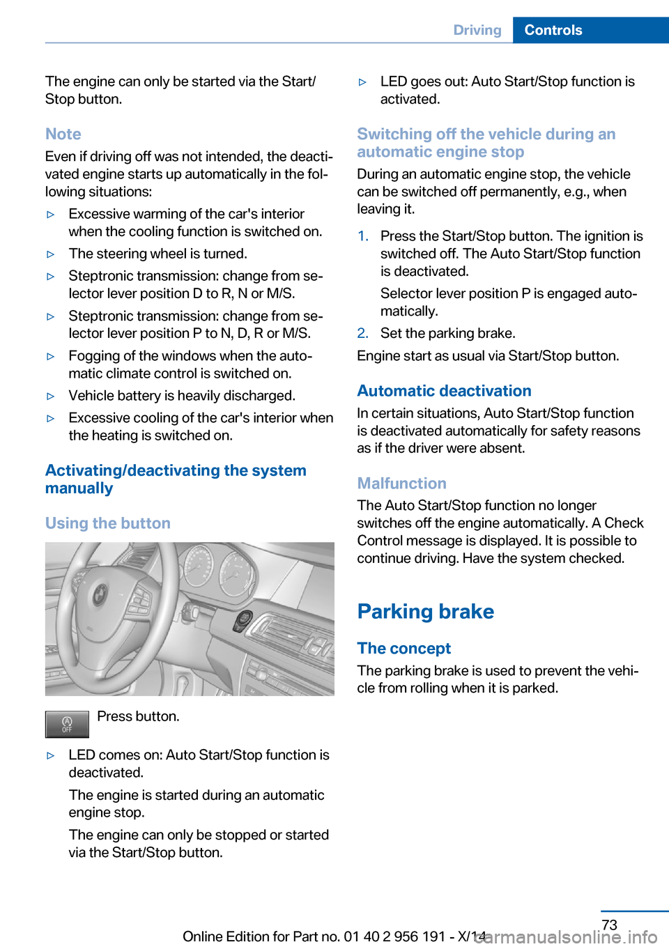
Activating/deactivating the system
manually
Using the button
Press button.
▷LED comes on: Auto Start/Stop function is
deactivated.
The engine is started during an automatic
engine stop.
The engine can only be stopped or started
via the Start/Stop button.▷LED goes out: Auto Start/Stop function is
activated.
Switching off the vehicle during an
automatic engine stop
During an automatic engine stop, the vehicle
can be switched off permanently, e.g., when
leaving it.
1.Press the Start/Stop button. The ignition is
switched off. The Auto Start/Stop function
is deactivated.
Selector lever position P is engaged auto‐
matically.2.Set the parking brake.
Engine start as usual via Start/Stop button.
Automatic deactivation
In certain situations, Auto Start/Stop function
is deactivated automatically for safety reasons
as if the driver were absent.
Malfunction
The Auto Start/Stop function no longer
switches off the engine automatically. A Check
Control message is displayed. It is possible to
continue driving. Have the system checked.
Parking brake The concept
The parking brake is used to prevent the vehi‐
cle from rolling when it is parked.
Seite 73DrivingControls73
Online Edition for Part no. 01 40 2 956 191 - X/14
Page 86 of 259
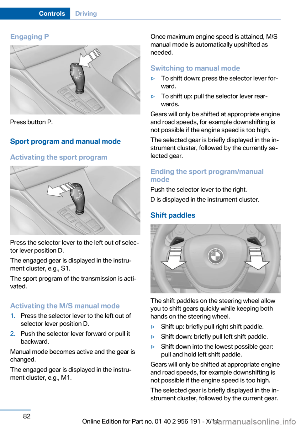
Engaging P
Press button P.Sport program and manual mode
Activating the sport program
Press the selector lever to the left out of selec‐
tor lever position D.
The engaged gear is displayed in the instru‐
ment cluster, e.g., S1.
The sport program of the transmission is acti‐
vated.
Activating the M/S manual mode
1.Press the selector lever to the left out of
selector lever position D.2.Push the selector lever forward or pull it
backward.
Manual mode becomes active and the gear is
changed.
The engaged gear is displayed in the instru‐
ment cluster, e.g., M1.
Once maximum engine speed is attained, M/S
manual mode is automatically upshifted as
needed.
Switching to manual mode▷To shift down: press the selector lever for‐
ward.▷To shift up: pull the selector lever rear‐
wards.
Gears will only be shifted at appropriate engine
and road speeds, for example downshifting is
not possible if the engine speed is too high.
The selected gear is briefly displayed in the in‐
strument cluster, followed by the currently se‐
lected gear.
Ending the sport program/manual
mode
Push the selector lever to the right.
D is displayed in the instrument cluster.
Shift paddles
The shift paddles on the steering wheel allow
you to shift gears quickly while keeping both
hands on the steering wheel.
▷Shift up: briefly pull right shift paddle.▷Shift down: briefly pull left shift paddle.▷Shift down into the lowest possible gear:
pull and hold left shift paddle.
Gears will only be shifted at appropriate engine
and road speeds, for example downshifting is
not possible if the engine speed is too high.
The selected gear is briefly displayed in the in‐
strument cluster, followed by the current gear.
Seite 82ControlsDriving82
Online Edition for Part no. 01 40 2 956 191 - X/14
Page 114 of 259
factured. After installing a child seat, make
sure that the indicator lamp for the front-seat
passenger airbags lights up. This indicates
that the child seat has been detected and the
front-seat passenger airbags are not activated.
Strength of the driver's and front-seat
passenger airbag
The explosive power that activates driver's/
front passenger's airbags very much depends
on the positions of the driver's/front passeng‐
er's seat.
With a respective message appearing on Con‐
trol Display calibrate the front seats to keep
the accuracy of this function over the long-
term.
Calibrating the front seats A corresponding message appears on the
Control Display.1.Press the reel and move the respective
seat all the way forward.2.Press the reel forward again. The seat still
moves forward slightly.3.Readjust the seat to the desired position.
The calibration procedure is completed when
the message on the Control Display disap‐
pears.
If the message continues to be displayed, re‐
peat the calibration.
If the message does not disappear after a re‐
peat calibration, have the system checked as
soon as possible.
Unobstructed area of movement
Ensure that the area of movement of the
seats is unobstructed to avoid personal injury
or damage to objects.◀
FTM Flat Tire Monitor
The concept
The system detects tire inflation pressure loss
on the basis of rotation speed differences be‐
tween the individual wheels while driving.
In the event of a tire inflation pressure loss, the
diameter and therefore the rotational speed of
the corresponding wheel changes. This will be
detected and reported as a flat tire.
The system does not measure the actual infla‐
tion pressure in the tires.
Functional requirements
The system must have been initialized when
the tire inflation pressure was correct; other‐
wise, reliable flagging of a flat tire is not as‐
sured. Initialize the system after each correc‐
tion of the tire inflation pressure and after
every tire or wheel change.
Status display The current status of the Flat Tire Monitor canbe displayed on the Control Display, e.g.,
whether or not the FTM is active.
On the Control Display:1."Vehicle info"2."Vehicle status"3. "Flat Tire Monitor (FTM)"
The status is displayed.
Initialization
When initializing the once set inflation tire
pressures serve as reference values in order to
detect a flat tire. Initialization is started by con‐
firming the tire inflation pressures.
Do not initialize the system when driving with
snow chains.
On the Control Display:
1."Vehicle info"2."Vehicle status"Seite 110ControlsSafety110
Online Edition for Part no. 01 40 2 956 191 - X/14
Page 116 of 259

The possible driving distance after a loss of tire
inflation pressure depends on cargo load, driv‐
ing style and road conditions.
A vehicle with an average load has a possible
driving range of approx. 50 miles/80 km.
A vehicle with a damaged tire reacts differ‐
ently, e.g., it has reduced lane stability during
braking, a longer braking distance and different
self-steering properties. Adjust your driving
style accordingly. Avoid abrupt steering ma‐
neuvers or driving over obstacles, e.g., curbs,
potholes, etc.
Because the possible driving distance de‐
pends on how the vehicle is used during the
trip, the actual distance may be shorter or lon‐
ger depending on the driving speed, road con‐
ditions, external temperature, cargo load, etc.
Continued driving with a flat tire
Drive moderately and do not exceed a
speed of 50 mph/80 km/h.
Your car handles differently when you lose tire
inflation pressure, e.g., your lane stability is re‐
duced when braking, braking distances are
longer and the self-steering properties will
change.◀
Final tire failure
Vibrations or loud noises while driving
can indicate the final failure of a tire. Reduce
speed and stop; otherwise, pieces of the tire
could come loose and cause an accident. Do
not continue driving and contact your service
center.◀
Tire Pressure Monitor TPM
The concept
The system monitors tire inflation pressure in
the four mounted tires. The system warns you
if there is a significant loss of pressure in one
or more tires. For this purpose, sensors in the
tire valves measure the tire inflation pressure
and tire temperature.Hints
Tire damage due to external factors
Sudden tire damage caused by external
circumstances cannot be recognized in ad‐
vance.◀
With use of the system observe further infor‐
mation found under Tire inflation pressure, re‐
fer to page 202.
Functional requirements
The system must have been reset with the
correct tire inflation pressure; otherwise, relia‐
ble signaling of tire inflation pressure loss is
not assured.
Reset the system after each adjustment of the
tire inflation pressure and after every tire or
wheel change.
Always use wheels with TPM electronics to
ensure that the system will operate properly.
Status display
The current status of the Tire Pressure Moni‐
tor TPM can be displayed on the Control Dis‐
play, e.g., whether or not the TPM is active.1."Vehicle info"2."Vehicle status"3. "Tire Pressure Monitor (TPM)"
The status is displayed.
Status control display Tire and system status are indicated by the
color of the wheels and a text message on the
Control Display.
All wheels green System is active and will issue a warning rela‐
tive to the tire inflation pressures stored during
the last reset.
One wheel is yellow A flat tire or major drop in inflation pressure in
the indicated tire.
Seite 112ControlsSafety112
Online Edition for Part no. 01 40 2 956 191 - X/14