2014 BMW 5 SERIES GRAN TURISMO height
[x] Cancel search: heightPage 64 of 259
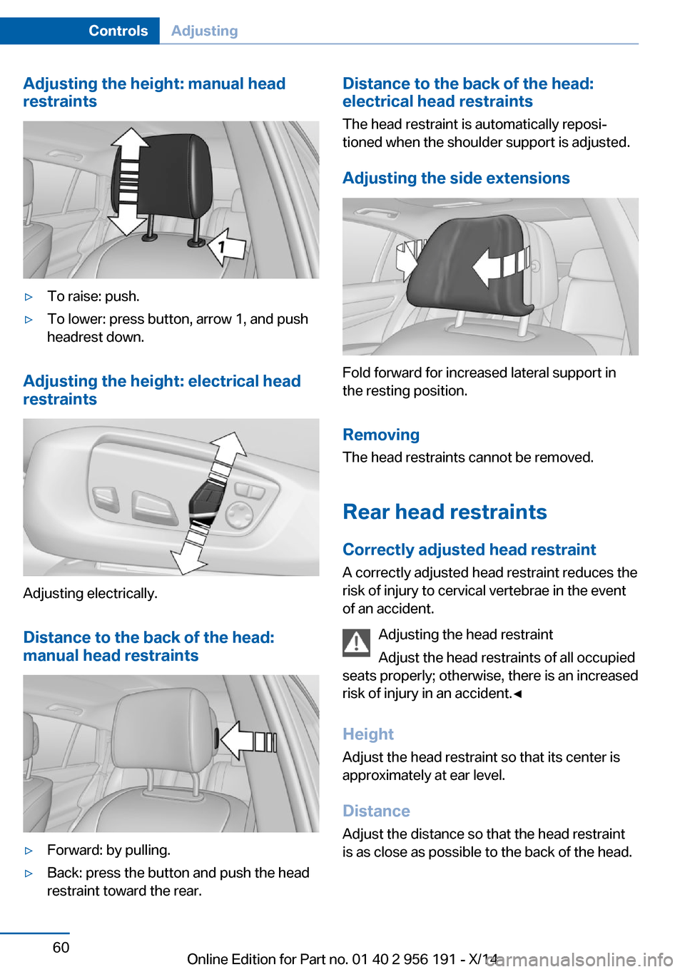
Adjusting the height: manual head
restraints▷To raise: push.▷To lower: press button, arrow 1, and push
headrest down.
Adjusting the height: electrical head
restraints
Adjusting electrically.
Distance to the back of the head:
manual head restraints
▷Forward: by pulling.▷Back: press the button and push the head
restraint toward the rear.Distance to the back of the head:
electrical head restraints
The head restraint is automatically reposi‐
tioned when the shoulder support is adjusted.
Adjusting the side extensions
Fold forward for increased lateral support in
the resting position.
Removing The head restraints cannot be removed.
Rear head restraints
Correctly adjusted head restraint A correctly adjusted head restraint reduces the
risk of injury to cervical vertebrae in the event
of an accident.
Adjusting the head restraint
Adjust the head restraints of all occupied
seats properly; otherwise, there is an increased
risk of injury in an accident.◀
Height
Adjust the head restraint so that its center is
approximately at ear level.
Distance
Adjust the distance so that the head restraint
is as close as possible to the back of the head.
Seite 60ControlsAdjusting60
Online Edition for Part no. 01 40 2 956 191 - X/14
Page 65 of 259
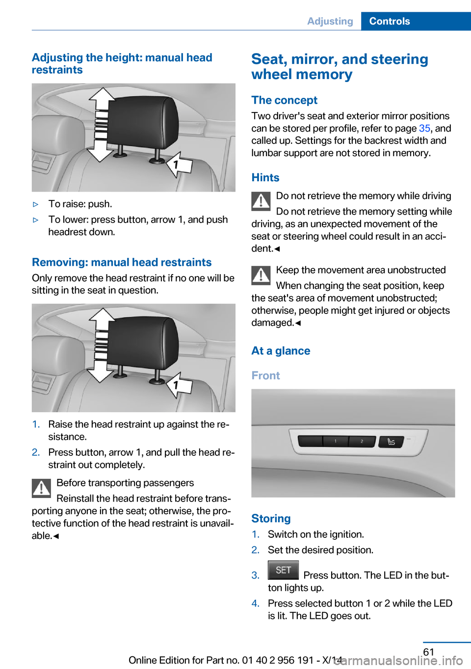
Adjusting the height: manual head
restraints▷To raise: push.▷To lower: press button, arrow 1, and push
headrest down.
Removing: manual head restraints
Only remove the head restraint if no one will be
sitting in the seat in question.
1.Raise the head restraint up against the re‐
sistance.2.Press button, arrow 1, and pull the head re‐
straint out completely.
Before transporting passengers
Reinstall the head restraint before trans‐
porting anyone in the seat; otherwise, the pro‐
tective function of the head restraint is unavail‐
able.◀
Seat, mirror, and steering
wheel memory
The concept
Two driver's seat and exterior mirror positions
can be stored per profile, refer to page 35, and
called up. Settings for the backrest width and
lumbar support are not stored in memory.
Hints Do not retrieve the memory while driving
Do not retrieve the memory setting while
driving, as an unexpected movement of the
seat or steering wheel could result in an acci‐
dent.◀
Keep the movement area unobstructed
When changing the seat position, keep
the seat's area of movement unobstructed;
otherwise, people might get injured or objects
damaged.◀
At a glance
Front
Storing
1.Switch on the ignition.2.Set the desired position.3. Press button. The LED in the but‐
ton lights up.4.Press selected button 1 or 2 while the LED
is lit. The LED goes out.Seite 61AdjustingControls61
Online Edition for Part no. 01 40 2 956 191 - X/14
Page 68 of 259

▷Do not cover the area between the inside
rearview mirror and the windshield.
Steering wheel
Note Do not adjust while driving
Do not adjust the steering wheel while
driving; otherwise, an unexpected movement
could result in an accident.◀
Manual steering wheel adjustment
1.Fold the lever down.2.Move the steering wheel to the preferred
height and angle to suit your seating posi‐
tion.3.Fold the lever back.
Power steering wheel adjustment
The steering wheel can be adjusted in four di‐
rections.
Storing the position
Seat, mirror, and steering wheel memory, refer
to page 61.
Steering wheel heating
Press button.
▷On: the LED lights up.▷Off: the LED goes out.
If the trip is resumed within approx. 15 min,
steering wheel heating is automatically acti‐
vated again.
Seite 64ControlsAdjusting64
Online Edition for Part no. 01 40 2 956 191 - X/14
Page 70 of 259
of unexpected movement of the rear seat
backrest.◀
On the front passenger seat
Deactivating airbags Deactivating the front-seat passenger
airbags
If a child restraint system is used in the front
passenger seat, deactivate the front-seat pas‐
senger airbags; otherwise, there is an in‐
creased risk of injury to the child when the air‐
bags are activated, even with a child restraint
system.◀
After installing a child restraint system in the
front passenger seat, make sure that the front,
knee and side airbags on the front passenger
side are deactivated.
Deactivate the front-seat passenger airbags
automatically, refer to page 109.
Seat position and height
Before installing a child restraint system, move
the front passenger seat as far back as possi‐
ble and bring it up to medium height to obtain
the best possible position for the belt and to
offer optimal protection in the event of an acci‐
dent.
If the upper anchorage of the safety belt is lo‐
cated in front of the belt guide of the child seat,
move the passenger seat carefully forward un‐
til the best possible belt guide position is
reached.
Backrest width Backrest width for the child seat
Before installing a child restraint system
in the front passenger seat, the backrest width
must be opened completely. Do not change
the adjustment after this; otherwise, the stabil‐
ity of the child seat will be reduced.◀
Adjustable backrest width: before installing a
child restraint system in the front passengerseat, open the backrest width completely. Do
not change the backrest width again and do
not call up a memory position.
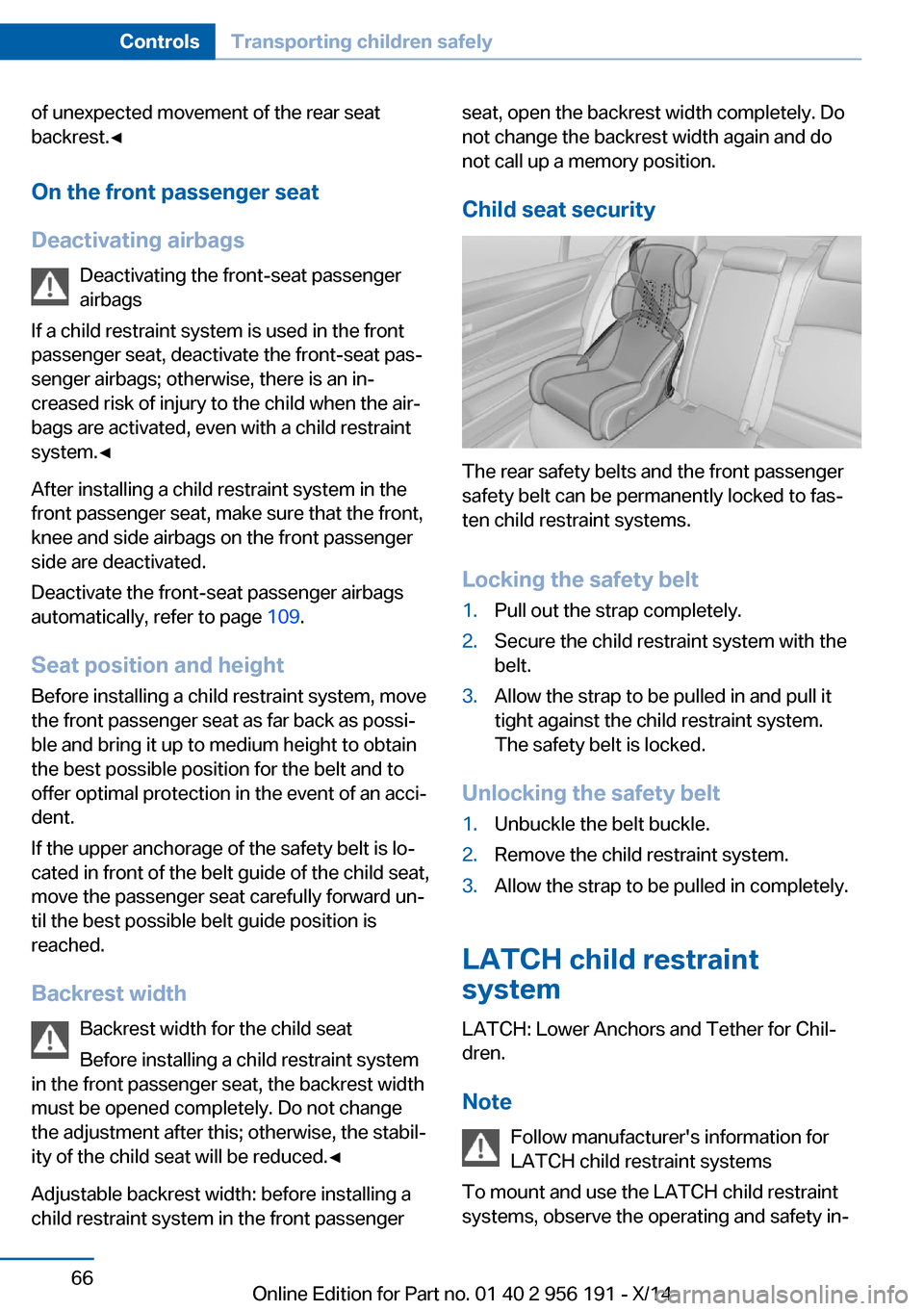
Child seat security
The rear safety belts and the front passenger
safety belt can be permanently locked to fas‐
ten child restraint systems.
Locking the safety belt
1.Pull out the strap completely.2.Secure the child restraint system with the
belt.3.Allow the strap to be pulled in and pull it
tight against the child restraint system.
The safety belt is locked.
Unlocking the safety belt
1.Unbuckle the belt buckle.2.Remove the child restraint system.3.Allow the strap to be pulled in completely.
LATCH child restraint
system
LATCH: Lower Anchors and Tether for Chil‐
dren.
Note Follow manufacturer's information for
LATCH child restraint systems
To mount and use the LATCH child restraint
systems, observe the operating and safety in‐
Seite 66ControlsTransporting children safely66
Online Edition for Part no. 01 40 2 956 191 - X/14
Page 105 of 259
Setting the brightness
The brightness is automatically adjusted to the
ambient brightness.
The basic setting can be adjusted manually.
On the Control Display:1."Settings"2."Head-Up Display"3."Brightness"4.Turn the controller.
When the low beams are activated, the bright‐
ness of the Head-up Display can be addition‐
ally influenced using the instrument lighting.
Settings are stored for the profile currently in
use.
Adjusting the height
On the Control Display:
1."Settings"2."Head-Up Display"3."Height"4.Turn the controller.
Settings are stored for the profile currently in
use.
Setting the rotation
On the Control Display:
1."Settings"2."Head-Up Display"3."Rotation"4.Turn the controller.
Settings are stored for the profile currently in
use.
Special windshield
The windshield is part of the system.
The shape of the windshield makes it possible
to display a precise image.
A film in the windshield prevents double im‐
ages from being displayed.
Therefore, have the special windshield re‐
placed by a service center only.Seite 101DisplaysControls101
Online Edition for Part no. 01 40 2 956 191 - X/14
Page 142 of 259
Self-leveling suspensionThe concept The self-leveling suspension keeps the vehicle
height and ground clearance constant. The
height of the vehicle at the rear axle is main‐
tained at a predefined level under all load con‐
ditions.
The system ensures consistent comfort by
keeping spring travel constant in all driving sit‐
uations.
Malfunction
A Check Control message is displayed. The system is disrupted. Vehicle handling may be
altered and driving comfort may be noticeably
reduced. Visit your nearest service center.
Driving Dynamics Control The concept
The Driving Dynamics Control can be used to
adjust the driving dynamics of the vehicle. For
this purpose various programs are available for
selection that are activated via the two buttons
of the Driving Dynamics Control and the DSC
OFF-button.
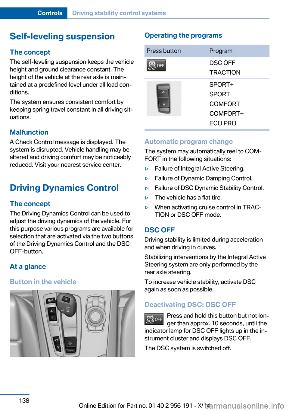
At a glance
Button in the vehicleOperating the programsPress buttonProgramDSC OFF
TRACTIONSPORT+
SPORT
COMFORT
COMFORT+
ECO PRO
Automatic program change
The system may automatically reel to COM‐
FORT in the following situations:
▷Failure of Integral Active Steering.▷Failure of Dynamic Damping Control.▷Failure of DSC Dynamic Stability Control.▷The vehicle has a flat tire.▷When activating cruise control in TRAC‐
TION or DSC OFF mode.
DSC OFF
Driving stability is limited during acceleration
and when driving in curves.
Stabilizing interventions by the Integral Active
Steering system are only performed by the
rear axle steering.
To increase vehicle stability, activate DSC
again as soon as possible.
Deactivating DSC: DSC OFF Press and hold this button but not lon‐
ger than approx. 10 seconds, until the
indicator lamp for DSC OFF lights up in the in‐
strument cluster and displays DSC OFF.
The DSC system is switched off.
Seite 138ControlsDriving stability control systems138
Online Edition for Part no. 01 40 2 956 191 - X/14
Page 160 of 259
Switch the system back on if needed.
Display
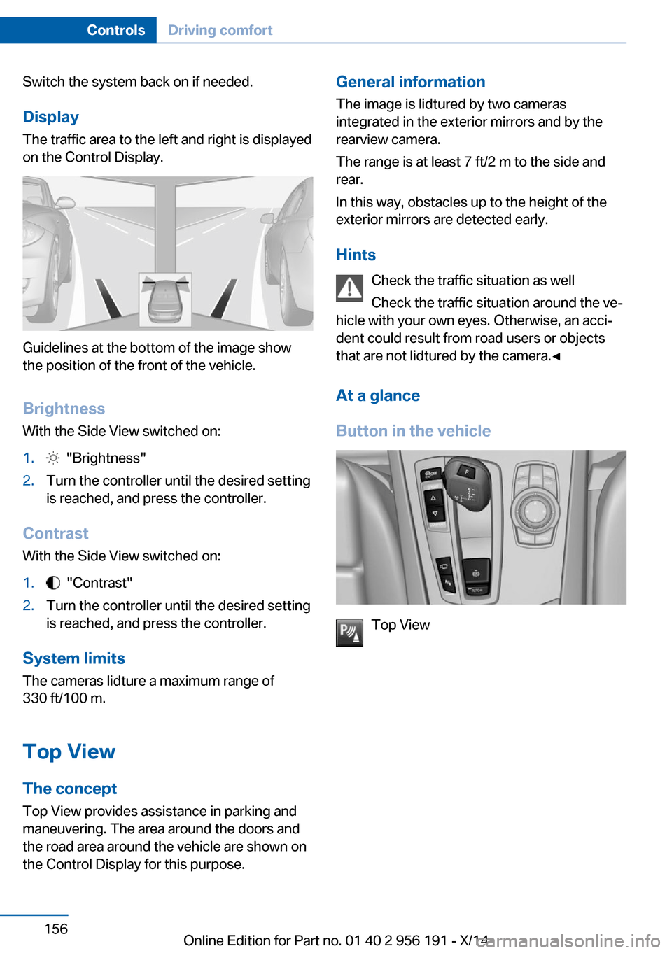
The traffic area to the left and right is displayed
on the Control Display.
Guidelines at the bottom of the image show
the position of the front of the vehicle.
Brightness With the Side View switched on:
1. "Brightness"2.Turn the controller until the desired setting
is reached, and press the controller.
Contrast
With the Side View switched on:
1. "Contrast"2.Turn the controller until the desired setting
is reached, and press the controller.
System limits
The cameras lidture a maximum range of
330 ft/100 m.
Top View
The concept Top View provides assistance in parking and
maneuvering. The area around the doors and
the road area around the vehicle are shown on
the Control Display for this purpose.
General information
The image is lidtured by two cameras
integrated in the exterior mirrors and by the
rearview camera.
The range is at least 7 ft/2 m to the side and
rear.
In this way, obstacles up to the height of the
exterior mirrors are detected early.
Hints Check the traffic situation as well
Check the traffic situation around the ve‐
hicle with your own eyes. Otherwise, an acci‐
dent could result from road users or objects
that are not lidtured by the camera.◀
At a glance
Button in the vehicle
Top View
Seite 156ControlsDriving comfort156
Online Edition for Part no. 01 40 2 956 191 - X/14
Page 189 of 259
sition mode, or when parked. Such contact
could lead to a fire, resulting in an increased
risk of serious personal injury as well as prop‐
erty damage.
Do not touch hot exhaust pipes; otherwise,
there is a danger of getting burned.◀
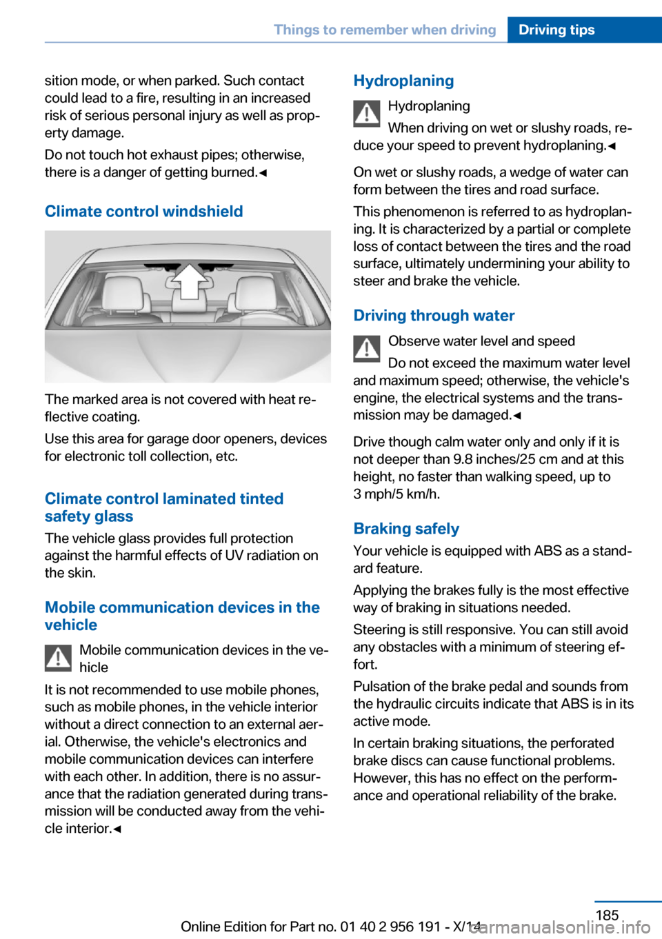
Climate control windshield
The marked area is not covered with heat re‐
flective coating.
Use this area for garage door openers, devices
for electronic toll collection, etc.
Climate control laminated tinted
safety glass
The vehicle glass provides full protection
against the harmful effects of UV radiation on
the skin.
Mobile communication devices in thevehicle
Mobile communication devices in the ve‐
hicle
It is not recommended to use mobile phones,
such as mobile phones, in the vehicle interior
without a direct connection to an external aer‐
ial. Otherwise, the vehicle's electronics and
mobile communication devices can interfere
with each other. In addition, there is no assur‐
ance that the radiation generated during trans‐
mission will be conducted away from the vehi‐
cle interior.◀
Hydroplaning
Hydroplaning
When driving on wet or slushy roads, re‐
duce your speed to prevent hydroplaning.◀
On wet or slushy roads, a wedge of water can
form between the tires and road surface.
This phenomenon is referred to as hydroplan‐
ing. It is characterized by a partial or complete
loss of contact between the tires and the road
surface, ultimately undermining your ability to
steer and brake the vehicle.
Driving through water Observe water level and speed
Do not exceed the maximum water level
and maximum speed; otherwise, the vehicle's
engine, the electrical systems and the trans‐
mission may be damaged.◀
Drive though calm water only and only if it is
not deeper than 9.8 inches/25 cm and at this
height, no faster than walking speed, up to
3 mph/5 km/h.
Braking safely Your vehicle is equipped with ABS as a stand‐
ard feature.
Applying the brakes fully is the most effective
way of braking in situations needed.
Steering is still responsive. You can still avoid
any obstacles with a minimum of steering ef‐
fort.
Pulsation of the brake pedal and sounds from
the hydraulic circuits indicate that ABS is in its
active mode.
In certain braking situations, the perforated
brake discs can cause functional problems.
However, this has no effect on the perform‐
ance and operational reliability of the brake.Seite 185Things to remember when drivingDriving tips185
Online Edition for Part no. 01 40 2 956 191 - X/14