2014 BMW 335I XDRIVE GRAN TURISMO mirror controls
[x] Cancel search: mirror controlsPage 112 of 240
NotesPersonal responsibility
The system cannot serve as a substitute
for the driver's personal judgment of the
course of the road and the traffic situation.
In the event of a warning, do not jerk the steer‐
ing wheel, as you may lose control of the vehi‐
cle.◀
At a glance
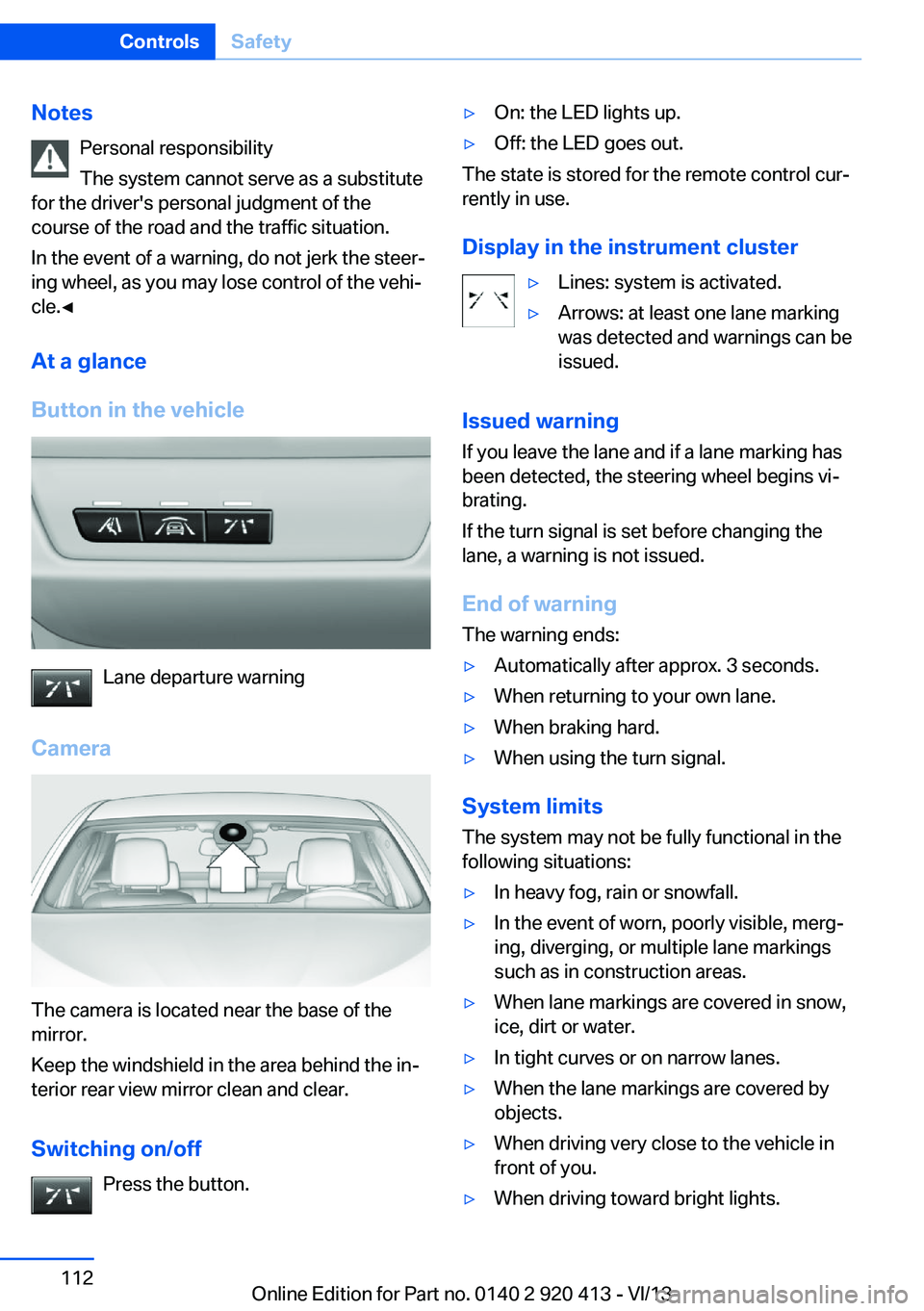
Button in the vehicle
Lane departure warning
Camera
The camera is located near the base of the
mirror.
Keep the windshield in the area behind the in‐
terior rear view mirror clean and clear.
Switching on/off Press the button.
▷On: the LED lights up.▷Off: the LED goes out.
The state is stored for the remote control cur‐
rently in use.
Display in the instrument cluster
▷Lines: system is activated.▷Arrows: at least one lane marking
was detected and warnings can be
issued.
Issued warning
If you leave the lane and if a lane marking has
been detected, the steering wheel begins vi‐
brating.
If the turn signal is set before changing the
lane, a warning is not issued.
End of warning
The warning ends:
▷Automatically after approx. 3 seconds.▷When returning to your own lane.▷When braking hard.▷When using the turn signal.
System limits
The system may not be fully functional in the
following situations:
▷In heavy fog, rain or snowfall.▷In the event of worn, poorly visible, merg‐
ing, diverging, or multiple lane markings
such as in construction areas.▷When lane markings are covered in snow,
ice, dirt or water.▷In tight curves or on narrow lanes.▷When the lane markings are covered by
objects.▷When driving very close to the vehicle in
front of you.▷When driving toward bright lights.Seite 112ControlsSafety112
Online Edition for Part no. 0140 2 920 413 - VI/13
Page 113 of 240
▷When the windshield in front of the interior
rearview mirror is fogged over, dirty or cov‐
ered with stickers, etc.▷During calibration of the camera immedi‐
ately after vehicle shipment.
Active Blind Spot Detection
The concept
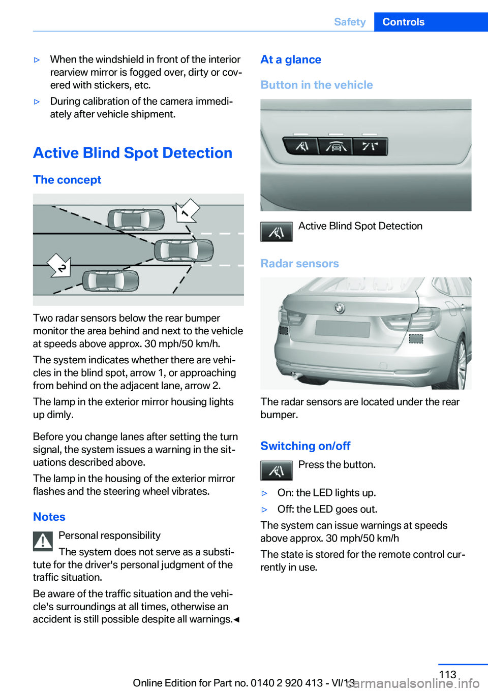
Two radar sensors below the rear bumper
monitor the area behind and next to the vehicle
at speeds above approx. 30 mph/50 km/h.
The system indicates whether there are vehi‐
cles in the blind spot, arrow 1, or approaching
from behind on the adjacent lane, arrow 2.
The lamp in the exterior mirror housing lights
up dimly.
Before you change lanes after setting the turn
signal, the system issues a warning in the sit‐
uations described above.
The lamp in the housing of the exterior mirror
flashes and the steering wheel vibrates.
Notes Personal responsibility
The system does not serve as a substi‐
tute for the driver's personal judgment of the
traffic situation.
Be aware of the traffic situation and the vehi‐
cle's surroundings at all times, otherwise an
accident is still possible despite all warnings.◀
At a glance
Button in the vehicle
Active Blind Spot Detection
Radar sensors
The radar sensors are located under the rear
bumper.
Switching on/off Press the button.
▷On: the LED lights up.▷Off: the LED goes out.
The system can issue warnings at speeds
above approx. 30 mph/50 km/h
The state is stored for the remote control cur‐
rently in use.
Seite 113SafetyControls113
Online Edition for Part no. 0140 2 920 413 - VI/13
Page 114 of 240
Display
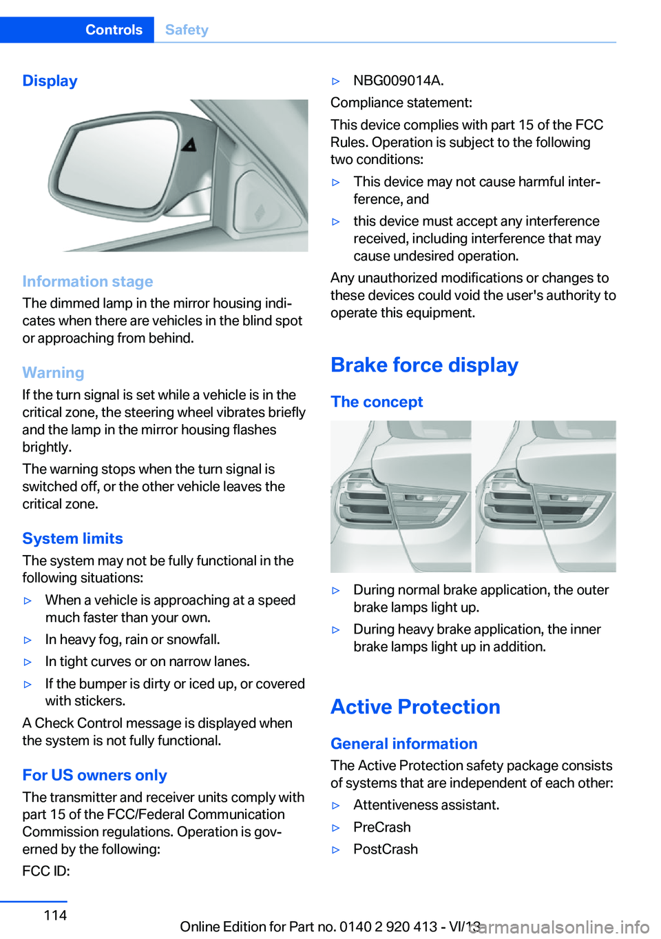
Information stage
The dimmed lamp in the mirror housing indi‐
cates when there are vehicles in the blind spot
or approaching from behind.
Warning
If the turn signal is set while a vehicle is in the
critical zone, the steering wheel vibrates briefly
and the lamp in the mirror housing flashes
brightly.
The warning stops when the turn signal is
switched off, or the other vehicle leaves the
critical zone.
System limits
The system may not be fully functional in the
following situations:
▷When a vehicle is approaching at a speed
much faster than your own.▷In heavy fog, rain or snowfall.▷In tight curves or on narrow lanes.▷If the bumper is dirty or iced up, or covered
with stickers.
A Check Control message is displayed when
the system is not fully functional.
For US owners only The transmitter and receiver units comply with
part 15 of the FCC/Federal Communication
Commission regulations. Operation is gov‐
erned by the following:
FCC ID:
▷NBG009014A.
Compliance statement:
This device complies with part 15 of the FCC
Rules. Operation is subject to the following
two conditions:
▷This device may not cause harmful inter‐
ference, and▷this device must accept any interference
received, including interference that may
cause undesired operation.
Any unauthorized modifications or changes to
these devices could void the user's authority to
operate this equipment.
Brake force display
The concept
▷During normal brake application, the outer
brake lamps light up.▷During heavy brake application, the inner
brake lamps light up in addition.
Active Protection
General information
The Active Protection safety package consists
of systems that are independent of each other:
▷Attentiveness assistant.▷PreCrash▷PostCrashSeite 114ControlsSafety114
Online Edition for Part no. 0140 2 920 413 - VI/13
Page 138 of 240
System limits
The cameras capture a maximum range of
330 ft/100 m.
Top View
The concept Top View assists you in parking and maneu‐
vering. The area around the doors and the road
area around the vehicle are shown on the Con‐
trol Display for this purpose.
General information
The image is captured by two cameras integrated in the exterior mirrors and by the
backup camera.
The range is at least 7 ft/2 m to the side and
rear.
In this way, obstacles up to the height of the
exterior mirrors are detected early.
Notes Check the traffic situation as well
Check the traffic situation around the ve‐
hicle with your own eyes. Otherwise, an acci‐
dent could result from road users or objects lo‐
cated outside the picture area of the
cameras.◀
At a glance
Button in the vehicleTop View
Cameras
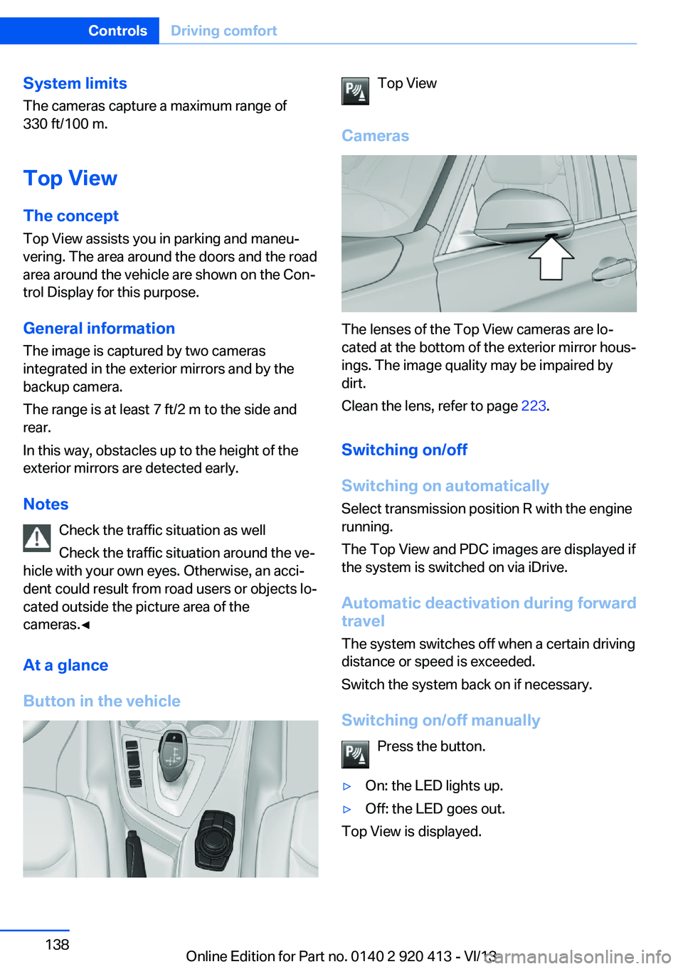
The lenses of the Top View cameras are lo‐
cated at the bottom of the exterior mirror hous‐
ings. The image quality may be impaired by
dirt.
Clean the lens, refer to page 223.
Switching on/off
Switching on automatically Select transmission position R with the engine
running.
The Top View and PDC images are displayed if
the system is switched on via iDrive.
Automatic deactivation during forward
travel
The system switches off when a certain driving
distance or speed is exceeded.
Switch the system back on if necessary.
Switching on/off manually Press the button.
▷On: the LED lights up.▷Off: the LED goes out.
Top View is displayed.
Seite 138ControlsDriving comfort138
Online Edition for Part no. 0140 2 920 413 - VI/13
Page 139 of 240
Switching on the backup camera via
the iDrive
With Top View switched on:
"Rear view camera"
The backup camera image is displayed. The
setting is stored for the remote control cur‐
rently in use.
Display
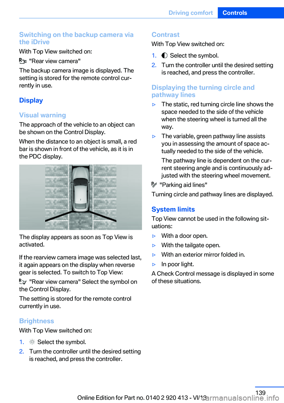
Visual warning The approach of the vehicle to an object can
be shown on the Control Display.
When the distance to an object is small, a red
bar is shown in front of the vehicle, as it is in
the PDC display.
The display appears as soon as Top View is
activated.
If the rearview camera image was selected last,
it again appears on the display when reverse
gear is selected. To switch to Top View:
"Rear view camera" Select the symbol on
the Control Display.
The setting is stored for the remote control
currently in use.
Brightness
With Top View switched on:
1. Select the symbol.2.Turn the controller until the desired setting
is reached, and press the controller.Contrast
With Top View switched on:1. Select the symbol.2.Turn the controller until the desired setting
is reached, and press the controller.
Displaying the turning circle and
pathway lines
▷The static, red turning circle line shows the
space needed to the side of the vehicle
when the steering wheel is turned all the
way.▷The variable, green pathway line assists
you in assessing the amount of space ac‐
tually needed to the side of the vehicle.
The pathway line is dependent on the cur‐
rent steering angle and is continuously ad‐
justed with the steering wheel movement.
"Parking aid lines"
Turning circle and pathway lines are displayed.
System limits
Top View cannot be used in the following sit‐
uations:
▷With a door open.▷With the tailgate open.▷With an exterior mirror folded in.▷In poor light.
A Check Control message is displayed in some
of these situations.
Seite 139Driving comfortControls139
Online Edition for Part no. 0140 2 920 413 - VI/13
Page 153 of 240
Interior equipmentVehicle equipmentAll standard, country-specific and optional
equipment that is offered in the model series is
described in this chapter. Therefore, equip‐
ment is also described that is not available in a
vehicle, e. g., because of the selected optional
equipment or country variant. This also applies
for safety-related functions and systems.
Integrated universal remote
control
The conceptThe integrated universal remote control can
operate up to 3 functions of remote-controlled
systems such as garage door drives or lighting
systems. The integrated universal remote con‐
trol replaces up to 3 different hand-held trans‐
mitters. To operate the remote control, the
buttons on the interior rearview mirror must be
programmed with the desired functions. The
hand-held transmitter for the particular system
is required in order to program the remote con‐
trol.
During programming
During programming and before activat‐
ing a device using the integrated universal re‐
mote control, ensure that there are no people,
animals, or objects in the range of movement
of the remote-controlled device; otherwise,
there is a risk of injury or damage.
Also follow the safety instructions of the hand-
held transmitter.◀
Before selling the vehicle, delete the stored
functions for the sake of security.Compatibility
If this symbol is printed on the packag‐
ing or in the instructions of the system
to be controlled, the system is gener‐
ally compatible with the integrated universal
remote control.
If you have any questions, please contact:▷Your service center.▷www.homelink.com on the Internet.
HomeLink is a registered trademark of John‐
son Controls, Inc.
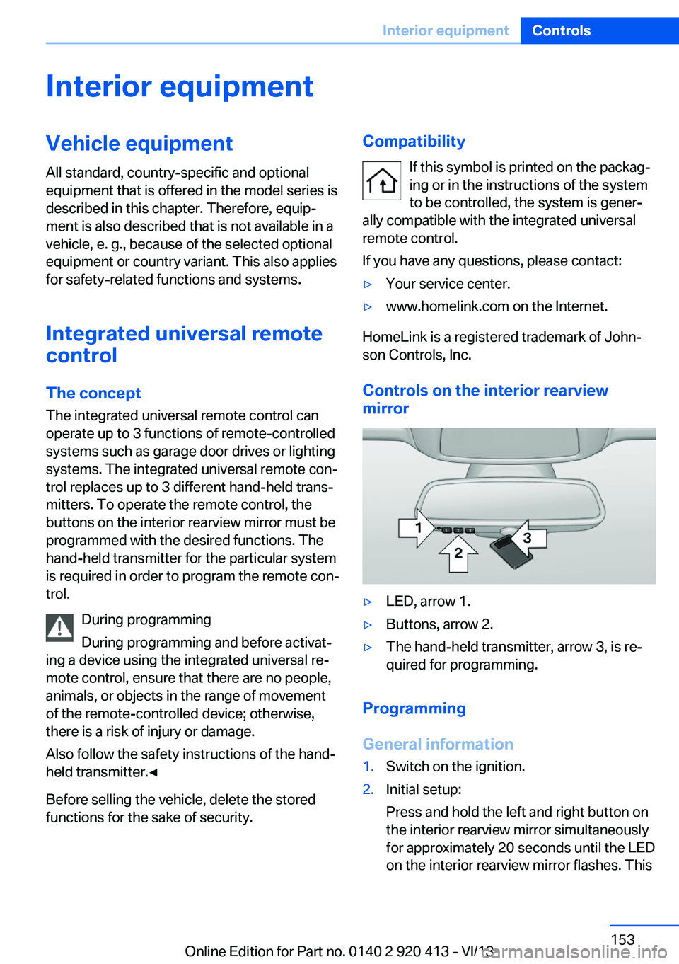
Controls on the interior rearview
mirror
▷LED, arrow 1.▷Buttons, arrow 2.▷The hand-held transmitter, arrow 3, is re‐
quired for programming.
Programming
General information
1.Switch on the ignition.2.Initial setup:
Press and hold the left and right button on
the interior rearview mirror simultaneously
for approximately 20 seconds until the LED
on the interior rearview mirror flashes. ThisSeite 153Interior equipmentControls153
Online Edition for Part no. 0140 2 920 413 - VI/13
Page 154 of 240
erases all programming of the buttons on
the interior rearview mirror.3.Hold the hand-held transmitter for the sys‐
tem to be controlled approx. 1 to 3 in/2.5 to
8 cm away from the buttons on the interior
rearview mirror. The required distance de‐
pends on the manual transmitter.4.Simultaneously press and hold the button
of the desired function on the hand-held
transmitter and the button to be program‐
med on the interior rearview mirror. The
LED on the interior rearview mirror will be‐
gin flashing slowly.5.Release both buttons as soon as the LED
flashes more rapidly. When the LED is
flashing faster, this indicates that the but‐
ton on the interior rearview mirror has been
programmed.
If the LED does not flash faster after at
least 60 seconds, change the distance be‐
tween the interior rearview mirror and the
hand-held transmitter and repeat the step.
Several more attempts at different distan‐
ces may be necessary. Wait at least
15 seconds between attempts.
Canada: if programming with the hand-
held transmitter was interrupted, hold
down the interior rearview mirror button
and repeatedly press and release the
hand-held transmitter button for 2 sec‐
onds.6.To program other functions on other but‐
tons, repeat steps 3 to 5.
The systems can be controlled using the inte‐
rior rearview mirror buttons.
Special feature of the alternating-
code wireless system
If you are unable to operate the system after
repeated programming, please check if the
system to be controlled features an alternat‐
ing-code system.
Read the system's operating manual, or press
the programmed button on the interior rear‐
view mirror longer. If the LED on the interior
rearview mirror starts flashing rapidly and then
stays lit constantly for 2 seconds, the system
features an alternating-code system. Flashing
and continuous illumination of the LED will re‐
peat for approximately 20 seconds.
For systems with an alternating-code system,
the integrated universal remote control and the
system also have to be synchronized.
Please read the operating manual of the sys‐
tem being set up for information on how to
synchronize the system.
Synchronizing is easier with the aid of a sec‐
ond person.
To synchronize:1.Park the vehicle within range of the re‐
mote-controlled system.2.Program the relevant button on the interior
rearview mirror as described.3.Locate and press the synchronizing button
on the system being programmed. You
have approx. 30 seconds for the next step.4.Hold down the programmed button on the
interior rearview mirror for approximately
3 seconds and then release it. If necessary,
repeat this work step up to three times in
order to finish synchronization. Once syn‐
chronization is complete, the programmed
function will be carried out.
Reprogramming individual buttons
1.Switch on the ignition.2.Press and hold the interior rearview mirror
button to be programmed.3.As soon as the interior rearview mirror LED
starts flashing slowly, hold the hand-held
transmitter for the system to be controlled
approx. 1 to 3 in/2.5 to 8 cm away from the
buttons on the interior rearview mirror. The
required distance depends on the manual
transmitter.Seite 154ControlsInterior equipment154
Online Edition for Part no. 0140 2 920 413 - VI/13
Page 155 of 240
4.Likewise, press and hold the button of the
desired function on the hand-held trans‐
mitter.5.Release both buttons as soon as the inte‐
rior rearview mirror LED flashes more rap‐
idly. When the LED is flashing faster, this
indicates that the button on the interior
rearview mirror has been programmed.
The system can then be controlled by the
button on the interior rearview mirror.
If the LED does not flash faster after at
least 60 seconds, change the distance and
repeat the step. Several more attempts at
different distances may be necessary. Wait
at least 15 seconds between attempts.
Canada: if programming with the hand-
held transmitter was interrupted, hold
down the interior rearview mirror button
and repeatedly press and release the
hand-held transmitter button for 2 sec‐
onds.
Controls
Before operation
Before operating a system using the
integrated universal remote control, ensure
that there are no people, animals, or objects
within the range of movement of the remote- controlled system; otherwise, there is a risk of
injury or damage.
Also follow the safety instructions of the hand-
held transmitter.◀
The system, such as the garage door, can be
operated using the button on the interior rear‐
view mirror while the engine is running or when
the ignition is started. To do this, hold down
the button within receiving range of the system
until the function is activated. The interior rear‐ view mirror LED stays lit while the wireless sig‐
nal is being transmitted.
Deleting stored functions Press and hold the left and right button on the
interior rearview mirror simultaneously for ap‐
proximately 20 seconds until the LED flashes
rapidly. All stored functions are deleted. The
functions cannot be deleted individually.
Digital compass
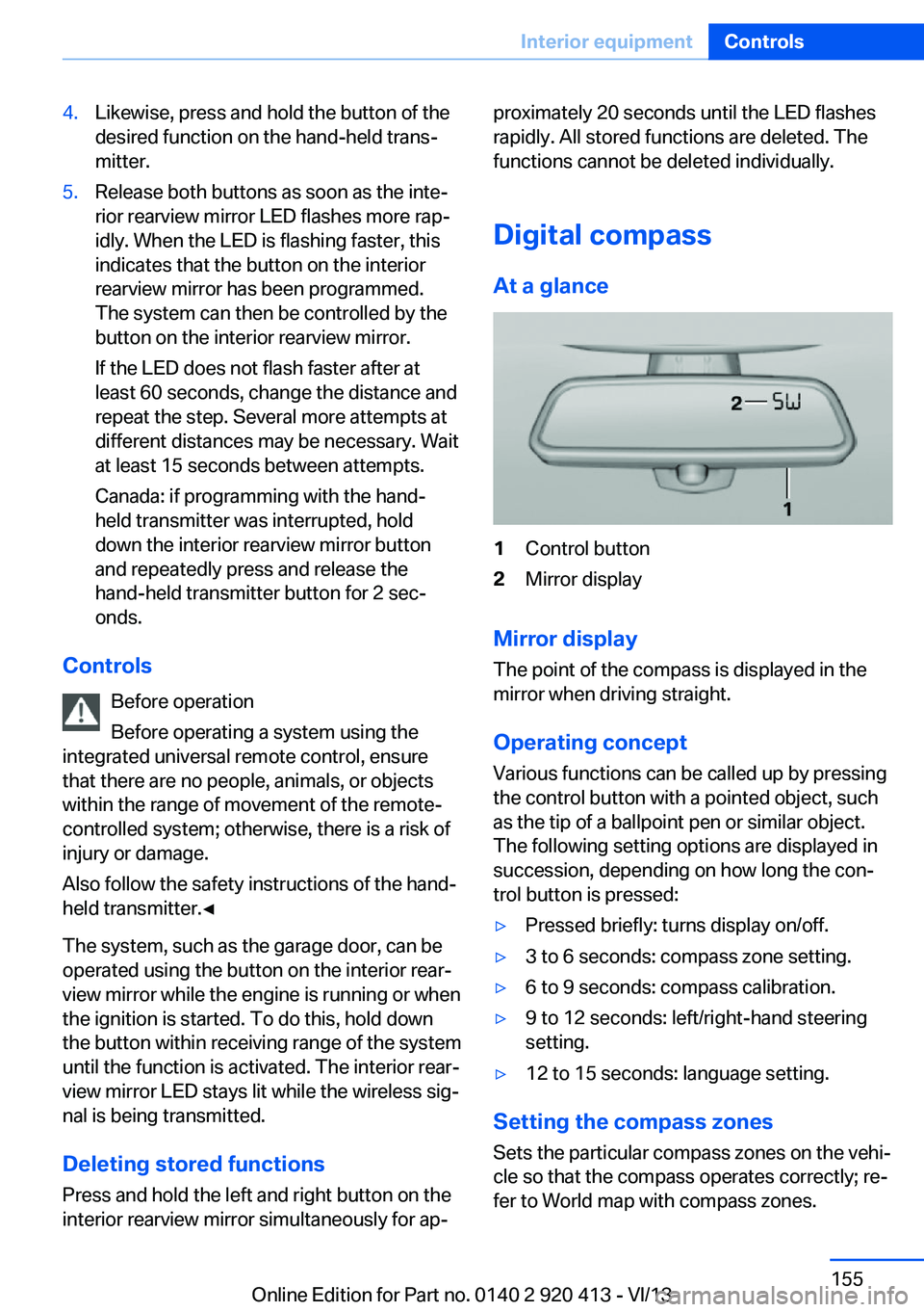
At a glance1Control button2Mirror display
Mirror display
The point of the compass is displayed in the
mirror when driving straight.
Operating concept
Various functions can be called up by pressing
the control button with a pointed object, such
as the tip of a ballpoint pen or similar object.
The following setting options are displayed in
succession, depending on how long the con‐
trol button is pressed:
▷Pressed briefly: turns display on/off.▷3 to 6 seconds: compass zone setting.▷6 to 9 seconds: compass calibration.▷9 to 12 seconds: left/right-hand steering
setting.▷12 to 15 seconds: language setting.
Setting the compass zones
Sets the particular compass zones on the vehi‐
cle so that the compass operates correctly; re‐
fer to World map with compass zones.
Seite 155Interior equipmentControls155
Online Edition for Part no. 0140 2 920 413 - VI/13