2014 BMW 328I XDRIVE SPORTS WAGON remote control
[x] Cancel search: remote controlPage 118 of 244
The DSC OFF indicator lamp lights up:
Dynamic Traction Control is activated.
SPORT Consistently sporty tuning of the suspension
and engine control for greater driving agility
with maximum driving stabilization.
The program can be configured to individual
specifications. The configuration is stored for
the remote control currently in use.
Activating SPORT Press button repeatedly until SPORT
is displayed in the instrument cluster.
Configuring SPORT When the display is activated on the ControlDisplay, refer to page 119, the SPORT driving
mode can be set to individual specifications.▷Activating SPORT.▷"Configure SPORT"▷Configuring the SPORT driving mode.
SPORT can also be configured before it is acti‐
vated:
1."Settings"2."Driving mode"3."Configure SPORT"4.Configure driving mode.
This configuration is retrieved when the
SPORT driving mode is activated.
COMFORT For a balanced tuning with maximum driving
stabilization.
Activating COMFORT Press button repeatedly until COM‐
FORT is displayed in the instrument
cluster.
In certain situations, the system automatically
changes to the NORMAL program, automatic
program change, refer to page 117.
ECO PRO ECO PRO, refer to page 175, provides consis‐
tent tuning to minimize fuel consumption for
maximum range with maximum driving stabili‐
zation.
Comfort functions and the engine controller
are adjusted.
The program can be configured to individual
specifications.
Activating ECO PRO Press button repeatedly until ECO
PRO is displayed in the instrument
cluster.
Configuring ECO PRO1.Activate ECO PRO.2."Configure ECO PRO"
Make the desired settings.
Configuring drive program
Settings can be made for the following driving
programs in Driving mode:
▷SPORT, refer to page 118.▷ECO PRO, refer to page 176.
Displays
Program selection Pressing the button displays a
list of the selectable programs.
Seite 118ControlsDriving stability control systems118
Online Edition for Part no. 01 40 2 925 793 - II/14
Page 130 of 244
Automatic deactivation during forward
travel
The system switches off when a certain driving
distance or speed is exceeded.
Switch the system back on if necessary.
With front PDC: switching on/off
manually
Press the button.▷On: the LED lights up.▷Off: the LED goes out.
Display
Signal tones When approaching an object, an intermittent
tone is sounded that indicates the position of
the object. For example, if an object is de‐
tected to the left rear of the vehicle, a signal
tone sounds from the left rear speaker.
The shorter the distance to the object be‐
comes, the shorter the intervals.
If the distance to a detected object is less than
approx. 10 in/25 cm, a continuous tone is
sounded.
With front PDC: if objects are located both in
front of and behind the vehicle, an alternating
continuous signal is sounded.
The signal tone is switched off:
▷When the vehicle moves away from an ob‐
ject by more than approx. 4 in/10 cm.▷When selector lever position P is engaged
on vehicles with automatic transmission.
Volume
The volume of the PDC signal tone can be ad‐
justed similar to the tone and volume settings
of the radio.
The setting is stored for the remote control
currently in use.
Visual warning
The approach of the vehicle to an object can
be shown on the Control Display. Objects that
are farther away are displayed on the Control
Display before a signal tone sounds.
A display appears as soon as Park Distance
Control (PDC) is activated.
The range of the sensors is represented in the
colors red, green and yellow.
When the image of the rearview camera is dis‐
played, the switch can be made to PDC:
"Rear view camera"
System limits
Limits of ultrasonic measurement The detection of objects can reach the physi‐
cal limits of ultrasonic measurement, e.g., in
the following circumstances:
▷For small children and animals.▷For persons with certain clothing, e.g.
coats.▷If there is an external disturbance of the ul‐
trasound, e.g. from passing vehicles or
loud machines.▷When sensors are dirty, iced over, dam‐
aged or out of position.▷Under certain weather conditions, such as
high relative humidity, rain, snowfall ex‐
treme heat or strong wind.▷With tow bars and trailer hitches of other
vehicles.▷With thin or wedge-shaped objects.▷With moving objects.▷With elevated, protruding objects such as
ledges or cargo.▷With objects with corners and sharp edges.▷With objects with a fine surface structure,
such as fences.▷For objects with porous surfaces.Seite 130ControlsDriving comfort130
Online Edition for Part no. 01 40 2 925 793 - II/14
Page 149 of 244
Interior equipmentVehicle equipmentAll standard, country-specific and optional
equipment that is offered in the model series is
described in this chapter. Therefore, equip‐
ment is also described that is not available in a
vehicle, e. g., because of the selected optional
equipment or country variant. This also applies
for safety-related functions and systems.
Universal garage door
opener
The concept
The universal garage door opener can operate
up to 3 functions of remote-controlled sys‐
tems such as garage door drives or lighting
systems. The universal garage door opener re‐
places up to 3 different hand-held transmitters.
To operate the remote control, the buttons on
the interior rearview mirror must be program‐
med with the desired functions. The hand-held
transmitter for the particular system is required
in order to program the remote control.
During programming
During programming and before activat‐
ing a device using the integrated universal re‐
mote control, ensure that there are no people,
animals, or objects in the range of movement
of the remote-controlled device; otherwise,
there is a risk of injury or damage.
Also follow the safety instructions of the hand-
held transmitter.◀
Before selling the vehicle, delete the stored
functions for the sake of security.
Compatibility If this symbol is printed on the packag‐
ing or in the instructions of the system
to be controlled, the system is gener‐ally compatible with the universal garage door
opener.
If you have any questions, please contact:▷Your service center.▷www.homelink.com on the Internet.
HomeLink is a registered trademark of John‐
son Controls, Inc.
Controls on the interior rearview
mirror
▷LED, arrow 1.▷Buttons, arrow 2.▷The hand-held transmitter, arrow 3, is re‐
quired for programming.
Programming
General information
1.Switch on the ignition.2.Initial setup:
Press and hold the left and right button on
the interior rearview mirror simultaneously
for approximately 20 seconds until the LED
on the interior rearview mirror flashes. This
erases all programming of the buttons on
the interior rearview mirror.3.Hold the hand-held transmitter for the sys‐
tem to be controlled approx. 1 to 3 in/2.5 to
8 cm away from the buttons on the interiorSeite 149Interior equipmentControls149
Online Edition for Part no. 01 40 2 925 793 - II/14
Page 151 of 244
indicates that the button on the interior
rearview mirror has been programmed.
The system can then be controlled by the
button on the interior rearview mirror.
If the LED does not flash faster after at
least 60 seconds, change the distance and
repeat the step. Several more attempts at
different distances may be necessary. Wait
at least 15 seconds between attempts.
Canada: if programming with the hand-
held transmitter was interrupted, hold
down the interior rearview mirror button
and repeatedly press and release the
hand-held transmitter button for 2 sec‐
onds.
Controls
Before operation
Before operating a system using the
integrated universal remote control, ensure
that there are no people, animals, or objects
within the range of movement of the remote- controlled system; otherwise, there is a risk of
injury or damage.
Also follow the safety instructions of the hand-
held transmitter.◀
The system, such as the garage door, can be
operated using the button on the interior rear‐
view mirror while the engine is running or when
the ignition is started. To do this, hold down
the button within receiving range of the system
until the function is activated. The interior rear‐ view mirror LED stays lit while the wireless sig‐
nal is being transmitted.
Deleting stored functions Press and hold the left and right button on the
interior rearview mirror simultaneously for ap‐
proximately 20 seconds until the LED flashes
rapidly. All stored functions are deleted. The
functions cannot be deleted individually.
Digital compass
At a glance1Control button2Mirror display
Mirror display
The point of the compass is displayed in the
mirror when driving straight.
Operating concept
Various functions can be called up by pressing
the control button with a pointed object, such
as the tip of a ballpoint pen or similar object.
The following setting options are displayed in
succession, depending on how long the con‐
trol button is pressed:
▷Pressed briefly: turns display on/off.▷3 to 6 seconds: compass zone setting.▷6 to 9 seconds: compass calibration.▷9 to 12 seconds: left/right-hand steering
setting.▷12 to 15 seconds: language setting.
Setting the compass zones
Sets the particular compass zones on the vehi‐
cle so that the compass operates correctly; re‐
fer to World map with compass zones.
Seite 151Interior equipmentControls151
Online Edition for Part no. 01 40 2 925 793 - II/14
Page 153 of 244
The setting is stored automatically after ap‐
proximately 10 seconds.
Ashtray/cigarette lighter
Ashtray
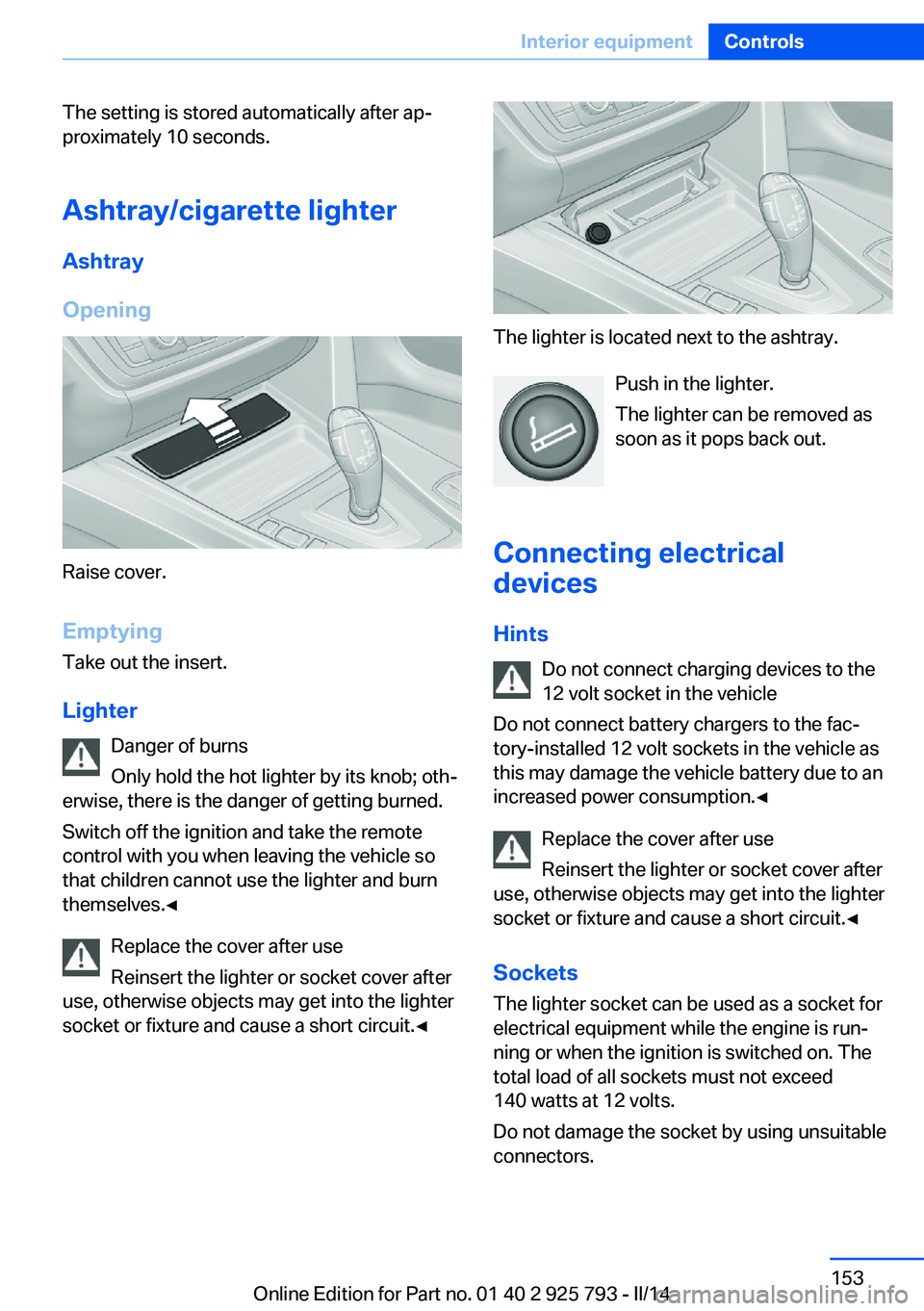
Opening
Raise cover.
EmptyingTake out the insert.
Lighter Danger of burns
Only hold the hot lighter by its knob; oth‐
erwise, there is the danger of getting burned.
Switch off the ignition and take the remote
control with you when leaving the vehicle so
that children cannot use the lighter and burn
themselves.◀
Replace the cover after use
Reinsert the lighter or socket cover after
use, otherwise objects may get into the lighter
socket or fixture and cause a short circuit.◀
The lighter is located next to the ashtray.
Push in the lighter.
The lighter can be removed as
soon as it pops back out.
Connecting electrical devices
Hints Do not connect charging devices to the
12 volt socket in the vehicle
Do not connect battery chargers to the fac‐
tory-installed 12 volt sockets in the vehicle as
this may damage the vehicle battery due to an
increased power consumption.◀
Replace the cover after use
Reinsert the lighter or socket cover after
use, otherwise objects may get into the lighter
socket or fixture and cause a short circuit.◀
Sockets
The lighter socket can be used as a socket for
electrical equipment while the engine is run‐
ning or when the ignition is switched on. The
total load of all sockets must not exceed
140 watts at 12 volts.
Do not damage the socket by using unsuitable
connectors.
Seite 153Interior equipmentControls153
Online Edition for Part no. 01 40 2 925 793 - II/14
Page 161 of 244
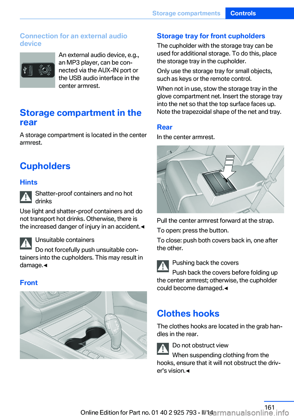
Connection for an external audio
device
An external audio device, e.g.,
an MP3 player, can be con‐
nected via the AUX-IN port or
the USB audio interface in the
center armrest.
Storage compartment in the
rear
A storage compartment is located in the center
armrest.
Cupholders
Hints Shatter-proof containers and no hot
drinks
Use light and shatter-proof containers and do
not transport hot drinks. Otherwise, there is
the increased danger of injury in an accident.◀
Unsuitable containers
Do not forcefully push unsuitable con‐
tainers into the cupholders. This may result in
damage.◀
FrontStorage tray for front cupholders
The cupholder with the storage tray can be
used for additional storage. To do this, place
the storage tray in the cupholder.
Only use the storage tray for small objects,
such as keys or the remote control.
When not in use, stow the storage tray in the
glove compartment net. Insert the storage tray
into the net so that the top surface faces up.
Note the trapezoidal shape of the net and tray.
RearIn the center armrest.
Pull the center armrest forward at the strap.
To open: press the button.
To close: push both covers back in, one after
the other.
Pushing back the covers
Push back the covers before folding up
the center armrest; otherwise, the cupholder
could become damaged.◀
Clothes hooks
The clothes hooks are located in the grab han‐
dles in the rear.
Do not obstruct view
When suspending clothing from the
hooks, ensure that it will not obstruct the driv‐
er's vision.◀
Seite 161Storage compartmentsControls161
Online Edition for Part no. 01 40 2 925 793 - II/14
Page 205 of 244
MaintenanceVehicle equipment
All standard, country-specific and optional
equipment that is offered in the model series is
described in this chapter. Therefore, equip‐
ment is also described that is not available in a
vehicle, e. g., because of the selected optional
equipment or country variant. This also applies
for safety-related functions and systems.
BMW maintenance system The maintenance system indicates required
maintenance measures, and thereby provides
support in maintaining road safety and the op‐ erational reliability of the vehicle.
Condition Based Service
CBS
Sensors and special algorithms take into ac‐
count the driving conditions of your vehicle.
Based on this, Condition Based Service deter‐
mines the maintenance requirements.
The system makes it possible to adapt the
amount of maintenance you need to your user
profile.
Detailed information on service requirements,
refer to page 81, can be displayed on the Con‐
trol Display.
Service data in the remote control Information on the required maintenance is
continuously stored in the remote control. Your service center will read out this data and
suggest the right array of service procedures
for your vehicle.
Therefore, hand your service specialist the re‐
mote control with which the vehicle was driven
most recently.Storage periods
Storage periods during which the vehicle bat‐
tery was disconnected are not taken into ac‐
count.
If this occurs, have a service center update the
time-dependent maintenance procedures,
such as checking brake fluid and, if necessary,
changing the engine oil and the microfilter/
activated-charcoal filter.
Service and Warranty Information Booklet for US
models and Warranty and
Service Guide Booklet for
Canadian models
Please consult your Service and Warranty In‐
formation Booklet for US models and Warranty
and Service Guide Booklet for Canadian mod‐ els for additional information on service re‐
quirements.
Maintenance and repair should be performed
by your service center. Make sure to have reg‐
ular maintenance procedures recorded in the
vehicle's Service and Warranty Information
Booklet for US models, and in the Warranty
and Service Guide Booklet for Canadian mod‐
els. These entries are proof of regular mainte‐
nance.
Socket for OBD Onboard
Diagnosis
Note Socket for Onboard Diagnosis
The socket for onboard diagnostics may
only be used by the service center or a work‐
shop that operates in accordance with the
specifications of the vehicle manufacturer withSeite 205MaintenanceMobility205
Online Edition for Part no. 01 40 2 925 793 - II/14
Page 234 of 244
Everything from A to Z
IndexA ABS, Antilock Brake Sys‐ tem 115
ACC, Active Cruise Control with Stop & Go 120
Acceleration Assistant, refer to Launch Control 73
Accessories and parts 7
Activated-charcoal filter 147
Active Blind Spot Detec‐ tion 112
Active Cruise Control with Stop & Go, ACC 120
Adaptive brake lights, refer to Brake force display 114
Adaptive Light Control 91
Additives, oil 202
Adjustments, seats/head re‐ straints 48
After washing vehicle 226
Airbags 95
Airbags, indicator/warning light 96
Air circulation, refer to Recir‐ culated-air mode 143, 146
Air, dehumidifying, refer to Cooling function 143, 146
Air distribution, manual 143, 147
Air flow, air conditioner 143
Air flow, automatic climate control 147
Air pressure, tires 191
Air vents, refer to Ventila‐ tion 147
Alarm system 42
Alarm, unintentional 43
All around the center con‐ sole 14
All around the headliner 15 All around the steering
wheel 12
All-season tires, refer to Win‐ ter tires 197
All-wheel-drive 116
Alternating-code hand-held transmitter 150
Alternative oil types 203
Antifreeze, washer fluid 70
Antilock Brake System, ABS 115
Anti-slip control, refer to DSC 115
Approved axle load 232
Approved engine oils 203
Arrival time 86
Ash tray 153
Assistance, Roadside Assis‐ tance 220
Assistance when driving off 119
Assist system information, on Control Display 88
AUTO intensity 146
Automatic car wash 225
Automatic climate con‐ trol 142
Automatic climate control with enhanced features 145
Automatic Cruise Control with Stop & Go 120
Automatic Curb Monitor 56
Automatic deactivation, front passenger airbags 97
Automatic headlamp con‐ trol 91
Automatic locking 42
Automatic recirculated-air control 146
Automatic tailgate 37 Automatic transmission with
Steptronic 70
AUTO program, automatic cli‐ mate control 145
AUTO program, climate con‐ trol 143
AUTO program, intensity 146
Auto Start/Stop function 64
Average fuel consumption 85
Average speed 85
Axle loads, weights 232
B Backrest curvature, refer to Lumbar support 50
Backrest, width 50
Band-aids, refer to First aid kit 220
Bar for tow-starting/ towing 223
Battery replacement, vehicle battery 216
Battery replacement, vehicle remote control 32
Battery, vehicle 216
Belts, safety belts 51
Beverage holder, cu‐ pholder 161
Blinds, sun protection 45
BMW Advanced Diesel 187
BMW Assist, see user's manual for Navigation, En‐
tertainment and Communi‐
cation
BMW Homepage 6
BMW Internet page 6
BMW maintenance sys‐ tem 205
Bonus range, ECO PRO 176 Seite 234ReferenceEverything from A to Z234
Online Edition for Part no. 01 40 2 925 793 - II/14