2014 BMW 2 SERIES interior light
[x] Cancel search: interior lightPage 107 of 228

NotePersonal responsibility
The system does not serve as a substi‐
tute for the driver's personal judgment of the
traffic situation.
Be aware of the traffic situation and the vehi‐
cle's surroundings at all times, otherwise acci‐
dents are still possible despite all warnings.◀
At a glance
Button in the vehicle
Intelligent Safety button
Camera
The camera is found near the interior rearview
mirror.
Keep the windshield in the area behind the in‐
terior rearview mirror clean and clear.
Switching on/offThe Intelligent Safety systems are automati‐
cally active after every departure.
Press button: the systems are turned
off. The LED goes out.
Press button: the systems are turned on. The
LED lights up.
Settings can be made on the Control Display.
Front-end collision warning
with City Braking function
The concept The ystem can help prevent accidents. If an
accident cannot be prevented, the system will
help reduce the collision speed.
The system sounds a warning before an immi‐
nent collision and actuates brakes independ‐
ently if needed.
The automatic braking intervention is done
with limited force and duration.
A camera in the area of the rearview mirror
controls the system.
The front-end collision warning is available
even if cruise control has been deactivated.
With the vehicle approaching another vehicle
intentionally the collision warning is delayed
avoiding false alarm.
Note Personal responsibility
The system does not serve as a substi‐
tute for the driver's personal judgment of the
traffic situation.
Be aware of the traffic situation and the vehi‐
cle's surroundings at all times, otherwise acci‐
dents are still possible despite all warnings.◀
General information The system warns at two levels of an imminent
danger of collision at speeds from approx.
3 mph/5 km/h. Time of warnings may vary with
the current driving situation.Seite 103SafetyControls103
Online Edition for Part no. 01 40 2 956 568 - X/14
Page 108 of 228

Appropriate braking kicks in at speeds of up to
35 mph/60 km/h.
Detection range
It responds to objects if they are detected by
the system.
At a glance
Button in the vehicle
Intelligent Safety button
Camera
The camera is found near the interior rearview
mirror.
Keep the windshield in the area behind the in‐
terior rearview mirror clean and clear.
Switching on/off
Switching on automatically The system is automatically active after every
driving-off.
Switch off Press button: the system is switched
off. The LED goes out.
Re-press button: the system is switched on.
The LED lights up.
Setting the warning time The warning time can be set via iDrive.1."Settings"2."Frontal Coll. Warning"3.Activate the desired time on the Control
Display.
The selected time is stored for the profile cur‐
rently in use.
Warning with braking function
Note Adapting your speed and driving style
The warning does not relieve the driver
of the responsibility to adapt his or her driving
speed and style to the traffic conditions.◀
Display
If a collision with a recognized vehicle is immi‐
nent a warning symbol appears in the instru‐
ment cluster and in the Head-Up Display.
Seite 104ControlsSafety104
Online Edition for Part no. 01 40 2 956 568 - X/14
Page 111 of 228

At a glance
Button in the vehicle
Intelligent Safety button
Camera
The camera is found near the interior rearview
mirror.
Keep the windshield in the area behind the in‐
terior rearview mirror clean and clear.
Switching on/off
Switching on automatically The system is automatically active after every
driving-off.
Switch off Press button: the systems are turned
off. The LED goes out.
Press button: the systems are turned on. The
LED lights up.
Warning with braking function
Note Adapting your speed and driving styleThe warning does not relieve the driver
of the responsibility to adapt his or her driving
speed and style to the traffic conditions.◀
Display If a collision with a person detected in this way
is imminent, a warning symbol appears on the
instrument cluster and in the Head-up Display.
The red symbol is displayed and a sig‐
nal sounds.
Intervene immediately by braking or make an
evasive maneuver.
Braking intervention The warning prompts the driver himself/herself
to react. During a warning, the maximum brak‐
ing force is used. Premise for the brake boos‐
ter is sufficiently quick and hard stepping on
the brake pedal. The system can assist with
some braking intervention if there is risk of a
collision. At low speeds vehicles may thus
come to a complete stop.
Manual transmission: During a braking inter‐
vention up to a complete stop, the engine may
be shut down.
The braking intervention is executed only if
DSC Dynamic Stability Control is switched on
and Dynamic Traction Control DTC is acti‐
vated.
The braking intervention can be interrupted by
stepping on the accelerator pedal or by ac‐
tively moving the steering wheel.
Object detection can be restricted. Limitations
of the detection range and functional restric‐
tions are to be considered.Seite 107SafetyControls107
Online Edition for Part no. 01 40 2 956 568 - X/14
Page 113 of 228

At a glance
Button in the vehicle
Lane departure warning
Camera
The camera is found near the interior rearview
mirror.
Keep the windshield in the area behind the in‐
terior rearview mirror clean and clear.
Switching on/off Press button.
▷On: the LED lights up.▷Off: the LED goes out.
Settings are stored for the profile currently in
use.
Display in the instrument cluster
▷Lines: system is activated.▷Arrows: at least one lane marking was de‐
tected and warnings can be issued.
Issued warning
If you leave the lane and if a lane marking has
been detected, the steering wheel begins vi‐
brating.
If the turn signal is set before changing the
lane, a warning is not issued.
End of warning
The warning ends:
▷Automatically after approx. 3 seconds.▷When returning to your own lane.▷When braking hard.▷When using the turn signal.
System limits
The system may not be fully functional in the
following situations:
▷In heavy fog, rain or snowfall.▷In the event of missing, worn, poorly visi‐
ble, merging, diverging, or multiple lane
markings such as in construction areas.▷When lane markings are covered in snow,
ice, dirt or water.▷In tight curves or on narrow lanes.▷When the lane markings are covered by
objects.▷When driving very close to the vehicle in
front of you.▷When driving toward bright lights.▷When the windshield in front of the interior
rearview mirror is fogged over, dirty or cov‐
ered with stickers, etc.▷During calibration of the camera immedi‐
ately after vehicle shipment.Seite 109SafetyControls109
Online Edition for Part no. 01 40 2 956 568 - X/14
Page 138 of 228

Parked-car ventilation
The concept The parked-car ventilation ventilates the vehi‐
cle interior and lowers its temperature, if
needed.
The system can be switched on and off at any
external temperature, either directly or by us‐
ing two preset reel-on times. It remains
switched on for 30 minutes.
Open the vents to allow air to flow out.
Switching on/off directly
On the Control Display:1."Settings"2."Climate"3."Activate comf. ventilation"
The symbol on the automatic climate con‐
trol flashes if the system is switched on.
Preselecting the reel-on time
On the Control Display:
1."Settings"2."Climate"3."Timer 1:" or "Timer 2:"4.Set the desired time.
Activating the reel-on time
On the Control Display:
1."Settings"2."Climate"3."Activate timer 1" or "Activate timer 2"
The symbol on the automatic climate con‐
trol lights up when the reel-on time is acti‐
vated.
The symbol on the automatic climate con‐
trol flashes when the system has been
switched on.
The system will only be switched on within the
next 24 hours. After that, it needs to be reacti‐
vated.Seite 134ControlsClimate control134
Online Edition for Part no. 01 40 2 956 568 - X/14
Page 139 of 228

Interior equipmentVehicle features and optionsThis chapter describes all standard, country-
specific and optional features offered with the
series. It also describes features that are not
necessarily available in your car, e. g., due to
the selected options or country versions. This
also applies to safety-related functions and
systems.
Universal Integrated RemoteControl
The concept
The universal garage door opener can operate
up to 3 functions of remote-controlled sys‐
tems such as garage door drives or lighting
systems. The universal garage door opener re‐
places up to 3 different hand-held transmitters.
To operate the remote control, the buttons on
the interior rearview mirror must be program‐
med with the desired functions. The hand-held
transmitter for the particular system is required
in order to program the remote control.
During programming
During programming and before activat‐
ing a device using the universal garage door
opener, ensure that there are no people, ani‐
mals or objects in the area of the remote-con‐
trolled device; otherwise, there is a risk of in‐
jury or damage.
Also follow the safety instructions of the hand-
held transmitter.◀
Before selling the vehicle, delete the stored
functions for the sake of security.
Compatibility If this symbol is printed on the packag‐
ing or in the instructions of the system
to be controlled, the system is gener‐ally compatible with the universal garage door
opener.
If you have any questions, please contact:▷Your service center.▷www.homelink.com on the Internet.
HomeLink is a registered trademark of Gentex
Corporation.
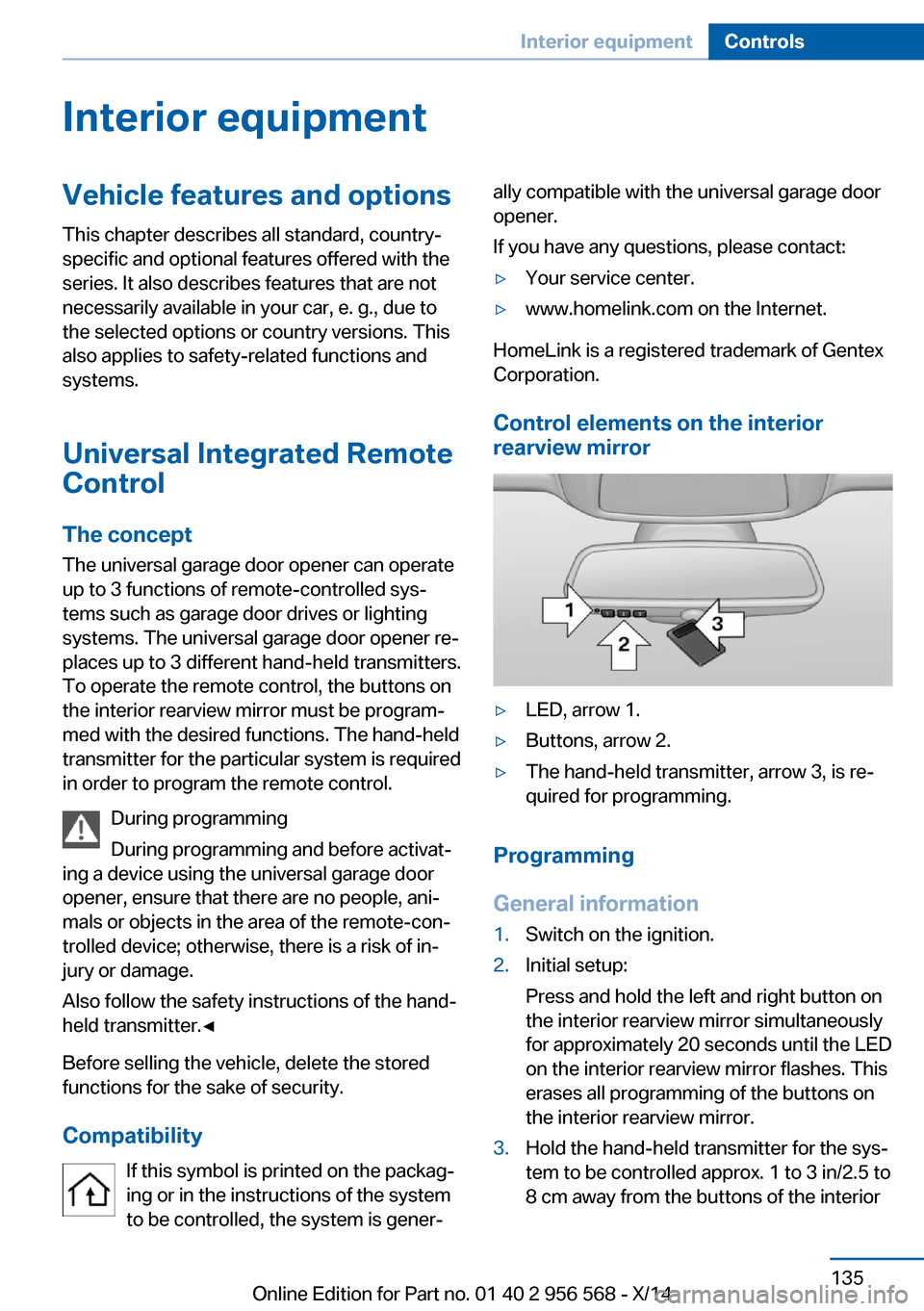
Control elements on the interior
rearview mirror
▷LED, arrow 1.▷Buttons, arrow 2.▷The hand-held transmitter, arrow 3, is re‐
quired for programming.
Programming
General information
1.Switch on the ignition.2.Initial setup:
Press and hold the left and right button on
the interior rearview mirror simultaneously
for approximately 20 seconds until the LED
on the interior rearview mirror flashes. This
erases all programming of the buttons on
the interior rearview mirror.3.Hold the hand-held transmitter for the sys‐
tem to be controlled approx. 1 to 3 in/2.5 to
8 cm away from the buttons of the interiorSeite 135Interior equipmentControls135
Online Edition for Part no. 01 40 2 956 568 - X/14
Page 143 of 228

Settings are stored automatically after approxi‐
mately 10 seconds.
Sun visor
Glare shield Fold the sun visor down or up.
Vanity mirror A vanity mirror is located in the sun visor be‐
hind a cover. When the cover is opened, the
mirror lighting switches on.
Ashtray/cigarette lighterAshtray
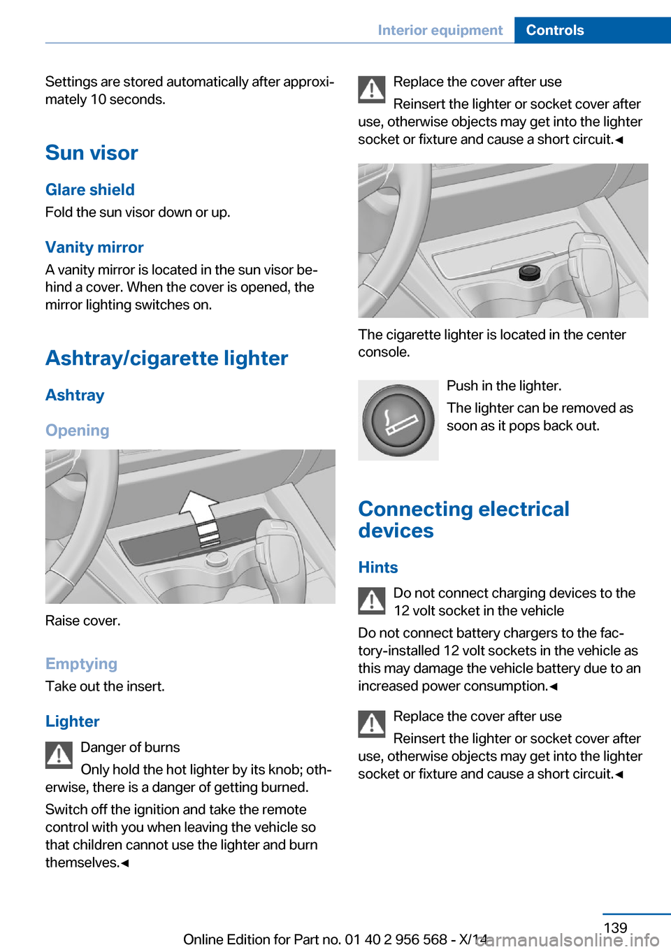
Opening
Raise cover.
EmptyingTake out the insert.
Lighter Danger of burns
Only hold the hot lighter by its knob; oth‐
erwise, there is a danger of getting burned.
Switch off the ignition and take the remote
control with you when leaving the vehicle so
that children cannot use the lighter and burn
themselves.◀
Replace the cover after use
Reinsert the lighter or socket cover after
use, otherwise objects may get into the lighter
socket or fixture and cause a short circuit.◀
The cigarette lighter is located in the center
console.
Push in the lighter.
The lighter can be removed as
soon as it pops back out.
Connecting electrical devices
Hints Do not connect charging devices to the
12 volt socket in the vehicle
Do not connect battery chargers to the fac‐
tory-installed 12 volt sockets in the vehicle as
this may damage the vehicle battery due to an
increased power consumption.◀
Replace the cover after use
Reinsert the lighter or socket cover after
use, otherwise objects may get into the lighter
socket or fixture and cause a short circuit.◀
Seite 139Interior equipmentControls139
Online Edition for Part no. 01 40 2 956 568 - X/14
Page 144 of 228

Sockets
General information
The lighter socket can be used as a socket for
electrical equipment while the engine is run‐
ning or when the ignition is switched on.
NoteThe total load of all sockets must not exceed
140 watts at 12 volts.
Do not damage the socket by using unsuitable
connectors.
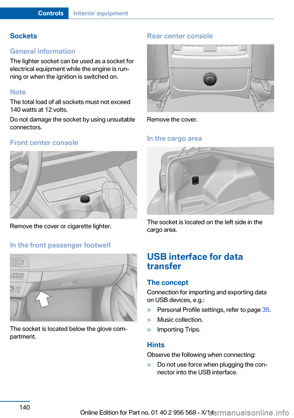
Front center console
Remove the cover or cigarette lighter.
In the front passenger footwell
The socket is located below the glove com‐
partment.
Rear center console
Remove the cover.
In the cargo area
The socket is located on the left side in the
cargo area.
USB interface for data
transfer
The concept Connection for importing and exporting data
on USB devices, e.g.:
▷Personal Profile settings, refer to page 35.▷Music collection.▷Importing Trips.
Hints
Observe the following when connecting:
▷Do not use force when plugging the con‐
nector into the USB interface.Seite 140ControlsInterior equipment140
Online Edition for Part no. 01 40 2 956 568 - X/14