2014 AUDI RS7 SPORTBACK key battery
[x] Cancel search: key batteryPage 15 of 292

Instrument s and warnin g/indic ator ligh ts 13
Yellow indi cator li ght s
•
Engine o il level
Yellow symbols indica te a priority 2 ma lf u nc-
c> page 17
tion -Warning!
Engine oil sensor
• I
US A models : Safety systems c>page 21
c> page 18
• Battery
&1
El
Canad a models : Safety systems c>page 16
c>page 18
Tank system
~
Bl
Electronic Stabilization Control c>page 21
(ESC) ./
c>page 18
•
Windshie ld washer fluid level
c> page 21
Electronic Stabiliza tion Control
I (ESC) ./
m
Windshie ld wipers
c> page 18 c>
page 21
•
Electronic Stabilization Control
Remote control key
( E SC) ./
II c>page 74
c>page 189
rJi3
USA models :
ll
Remote contro l key
Anti-lock braking system (ABS)
c>page 76
defect ive ./
c>page 19
!9
Battery in remote control key
Canada models :
c>page 33
[I] Anti-lock braking system (ABS)
J:I
Defective light bulb warning
defect ive ./
c>page 21
c>page 19
Rear fog lig ht(s)
•
Worn brake pads
II c>page 21
c>page20
•
E lect romechan ica l par king brake
II
Head light range control
c>page 21
c>page
77
[g
Tire pressure monitoring system
Fil
adaptive light*
c> page 21
./
c>page246
m
Light-/rain sensor faulty
mm Tire pressure monitor ing system c> page 22
c:::>page246
•
Audi active lane assist*
Im
Electronic power control./ c>page 91
c:::>page20
B
Adaptive dampers*
Malfunct ion ind icator Lamp (MIL)
c>page22
•
./
c>page20
•
Transmission
c> page 108
.,
Engine speed limitation
c> page20
Ill
Electronic steering column lock
c> page 17
Page 35 of 292

Removing the mechanical key
Fig. 21 Remote control maste r key : re mov ing the me
c han ical key
• Press the release button @ c:> fig. 21.
• Pull the mechanica l key @ out of the master
key.
Using the mechan ica l key, you can:
- lock and unlock the storage compartment
on the passenger's side
c::> page 61.
- lock and unlock the vehicle manually
c::>page 37 .
-lock the front and rear passenger doors me
chanically
c:> page 38.
Master key battery replacement
Fig . 22 Remote master key : Re mov ing the ba ttery
holde r
Check light in the master key
The check light @ in the master key provides
information about different cond itions .
• The check light comes on briefly once when
a button is pressed, and during an "inquiry"
by the conven ience key system .
• If the check light does not come on, the bat
tery is dead and has to be replaced . In add i
t ion, when the battery is dead the
I!! sym
bol appears in the instrument cluster dis-
Opening and closing 33
play as well as the message : Please change
key battery .
Master key battery replacement
• Pull the mechanical key out of the master
key
c::> page 33.
• Press the release button @ on the battery
holder and at the same time pull the battery
holder out of the master key in the direction
of the arrow.
• Install the new battery CR 2032 with the
"+ " sign facing down.
• Push the battery holder carefully into the
maste r key .
• Install the mechanical key.
@ For the sake of the environment
Dispose of dead batteries properly so as
not to poll ute the environment .
(D Tips
The replacement battery must be the
same specification as the original.
, Electronic immobilizer
The immobilizer helps to prevent unauthor
ized use of your vehicle .
A computer chip inside your key automatically
deactivates the electronic immobilizer when
the key is inside the vehicle. When you remove
the key from the vehicle, the electronic immo
bilizer is automatically activated once again .
A WARNING
-
Always take the key with you when you
leave the vehicle. The key can disarm the
e lectronic engine immobilizer and permit
an unauthorized person to start the engine
and enable operation of the vehicle sys
tems such as power window or power sun
roof leading to serious personal injury.
(D Tips
- Th e veh icle cannot be started if an unau
thorized key is used. The vehicle may not
start if another radio device such as a key .,.
Page 39 of 292
@ Tips
If your vehicle has been standing for an ex
tended period, please note the follow ing:
- The proximity sensors are deactivated af-
ter a few days to save power. You then
have to pull on the door handle once to
unlock the vehicle and a second time to
open the veh icle.
- To prevent the battery from being dis
charged and to preserve your veh icle's
ability to start for as long as possible,
the energy management system gradu
ally switches off unnecessary conven i ence funct ions. It is possible that you
will not be able to unlock your vehicle us
i ng these conven ien ce f unctions.
- Fo r De clarat ion of Compliance to United
Sta tes FCC and Indus try Canada regula
tions
¢page 276.
Operating locks with the key
In the event of a failure of the power locking
system, the driver's door can be locked and unlocked at the lock cylinder.
Fig. 25 Key turns for opening and clos ing .
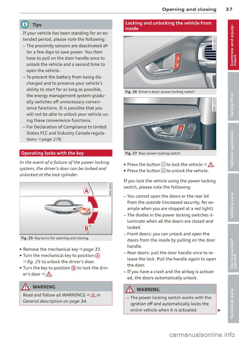
... Remove the mechanical key¢ page 33.
... Turn the mechanical key to position @
¢ fig. 25 to unlock the driver's door.
... Turn the key to position @ to lock the dr iv
er's door¢ &,.
,& WARNING
Read and follow a ll WARNINGS ¢ & in
General description on page 34.
Op enin g an d clos ing
Locking and unlocking the vehicle from
inside
Fig . 26 Dr ive r's door: power locking switch
Fig. 27 Rear power locking switch
... Press the button~ to lock the vehicle¢&, .
.,. Press the button
Im to unlock the vehicle.
If you lock the vehicle using the power locking
switch, p lease note the following:
- You cannot open the doors or the rear lid
from the
outside ( increased security, for ex
ample when you are stopped at a red light).
- The d iodes in the power locking switches il-
luminate when all the doors are closed and
locked.
- Front doors: you can unlock and open the
doors from the inside by pulling on the door
handle .
- Rear doors: pull the door handle
once to re
lease the lock. Pull the handle
again to open
the door .
- If you have a crash and the airbag is activat
ed the doors automatically unlock .
,
A WARNING
-The power lock ing switch works with the
ig nit ion off and automat ica lly locks the
enti re veh icle when it is actuated.
3 7
Page 43 of 292
![AUDI RS7 SPORTBACK 2014 Owners Manual .. To activate the child safety lock for the left/
right rear door, press the left/right button
Ii]
in the drivers door ¢ fig. 33. The light in the
button w ill turn on.
.. To AUDI RS7 SPORTBACK 2014 Owners Manual .. To activate the child safety lock for the left/
right rear door, press the left/right button
Ii]
in the drivers door ¢ fig. 33. The light in the
button w ill turn on.
.. To](/manual-img/6/57649/w960_57649-42.png)
.. To activate the child safety lock for the left/
right rear door, press the left/right button
Ii]
in the driver's door ¢ fig. 33. The light in the
button w ill turn on.
.. To deactivate the child safety lock for the
left/right rear door, press the left/r ight but
ton
1±1 in the driver's door. The light in the
button turns off.
The follow ing features are switched off:
- The interior door handles in the rear doors,
- The power windows in the rear doors.
I n order to activate the child safety lock on
the left and the right s ide, press the two safe
ty buttons
Ii] in succession.
Power windows
Controls
The driver can control all power windows.
Fig. 34 Section of the driver 's doo r: Cont rols
l(l 0 0 0
"' m
All power window switches are provided with
a two-position function :
Opening the windows
.. Press the switch to the first stop and hold it
until the window reaches the desired posi
tion.
.,. Press the switch br iefly to the
second stop
to automatically open the window.
Closing the windows
.. Pull the switch to the first stop and hold it
until the window reaches the desired posi
t ion.
.. Pull the switch briefly to the
second stop to
automatically close the window .
Opening and closing 41
Power window switches
@ Driver's door
® Passenger's door
© Left rear door
@ Right rear door
.,&_ WARNING
-When you leave your vehicle - even if on
ly briefly - always take the ignit ion key
with you. This applies particularly when children remain in the vehicle. Otherwise
the children could start the engine or op
erate electrical equipment (e.g. power
windows). The power windows are func
tional until the driver's door or passeng
er's doo r has been opened.
- Be careful when closing the w indows.
Check to see that no one is in the way, or
serio us injury could result!
- When locking the vehicle from outside,
the vehicle must be unoccupied since the
windows can no longer be opened in an
emergency .
{D Tips
-When you open the doors, the windows
automatically lower abo ut 10 mm.
- When the window in the driver's or pas
senger's door is complete ly open, it will
raise approximately 25 mm when the
door is opened. The window will lower
again when you close the door.
- After the ignition has been switched off,
the windows can sti ll be opened or
closed for about 10 minutes. The power
windows are not switched off until the
dr iver's door or passenger's door has
been opened .
What to do after a malfunction
The one-touch open and close function must
be reactivated if the battery has been discon
nected.
.. Pull and ho ld the power window switch until
the window is fully closed. .-
Page 62 of 292
60 Seats and st o rage
12-volt sockets
Appl ies to vehicles: wit h 12-volt sockets
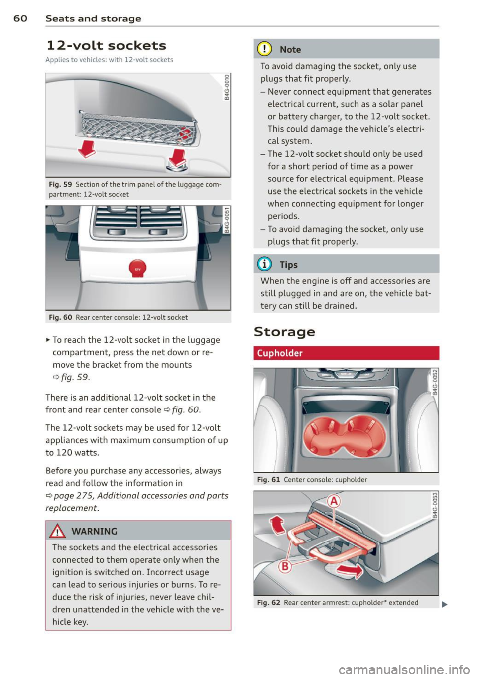
Fig. 59 Sect ion of the trim panel o f th e luggage com ·
par tm ent: 12-vol t so cket
-
Fig. 60 R ear cente r co nso le: 12-vo lt socke t
,. To reach the 12-volt socket in the luggage
compartment, press the net down or re
move the bracket from the mounts
¢ fig . 59.
There is an additional 12-vo lt socket in the
front and rear center console~
fig. 60.
0 5 0 6
~
The 12-volt sockets may be used for 12-volt
appliances with maximum consumption of up
to 120 watts.
Before you purchase any accessories, always
read and fo llow the information in
¢ page 2 75, Additional accessories and parts
replacement .
A WARNING
The sockets and the e lectrical accessories
connected to them operate only when the
ign ition is switched on. Incorrect usage
can lead to serious injur ies or burns. To re·
duce the risk of injuries, never leave chi l
dren unattended in the vehicle w ith the ve
hicle key.
(D Note
To avoid damaging the socket, only use plugs that fit properly.
- Never connect equipment that generates
electrical current, such as a solar pane l
or battery charger, to the 12-vo lt socket.
This could damage the vehicle's electri cal system.
- The 12-vo lt socket should on ly be used
for a short period of ti me as a power
source for electrical equ ipment . Please
use the electrical sockets in the vehicle
when connecting equ ipment for longer
periods.
- To avoid damaging the socket , only use
plugs that fit properly.
(0 Tips
When the engine is off and accessories are
still plugged in and are on , the vehicle bat
tery can still be drained.
Storage
Cupholder
F ig. 6 1 Ce nter co ns ole: c upho lde r
Fig. 62 Rear ce nter a rmrest : cupho ld er* extend ed
Page 78 of 292
76 On the road
Driver message in the instrument
cluster display
Turn off ignition befor e le a v ing car
This message appears and a warning tone
sounds if yo u open the dr iver's door when the
ignition is switched on.
Press brake p edal to start engin e
This message appears if you press the
I STAR T ENGINE ST OP ! button to start the en
g ine and do not depress the brake pedal. The
engine can on ly be started if the brake pedal
is depressed.
!I I s ke y in th e vehicle?
If the indicator light turns on and the mes
sage appears, the remote control key was re
moved from the vehicle while the engine was
running. If the ignit ion key is not in the vehi
cle you w ill not be able to sw itch on the ign i
tion or resta rt the engine after it has been
switched off. You w ill also not be ab le to lock
the veh icle from the outside.
Shift to P , oth erwise vehicl e can roll away.
Doors do not lo ck if lever i s not in P .
This message appears for safety reasons
along w ith an audib le warn ing tone if the P
selecto r lever posit io n is not engaged when
stopping the engine with the
I STAR T ENGINE ST OP ! button. Select the P se
lector lever pos it ion. Othe rwise the veh icle
could ro ll and it cannot be locked.
(I Key is n ot recogn iz e d . Ho ld b ack o f key
ag ain st marked ar ea . Se e owner's manual.
If the indicator light tu rns on and th is mes
sage appears, there is a malfunction
c::>page 76. Starting the engine if there is a
malfunction
It may not be possible to start the engine un
der certain circumstances, for example if the
battery in the vehicle key
is drained, if inter
ference has affected the key or if there
is a
system malfunction .
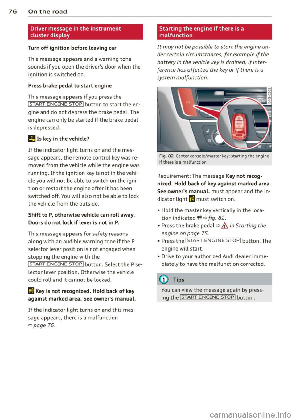
Fig . 82 Center console/master key: starting the eng ine
i f there is a malfunction
Req uirement: The message Ke y not r ecog
ni ze d. H old back of key aga inst ma rked are a.
Se e owne r's manual.
must appear and the in
dicator
light (I must switch on.
.,.. Ho ld the mas ter key vertically in the loca
tion indicated
y >l) r=:>fig. 82.
.,.. Press the brake pedal c::> A in Starting the
engine on page 75.
.,.. Press the I START ENGINE S T OP ! button. The
eng ine will start.
.,.. Dr ive to your authorized Audi dealer imme
diately to have the malfunction corrected.
(D Tips
You can v iew the message again by press
i ng the
I STAR T ENGINE STOP I button.
Page 97 of 292
Have your authorized Audi dealer or au
thorized A udi Service Facility check the ir
function.
@ Tips
- If the win dow g lass in the driver 's door
or front passenger's door has been tint
ed, the disp lay in the exterior m irror may
be misinterp reted .
- For Decla rat ion of Compliance to United
States FCC and Industry Canada regula
tions
¢ page 2 76.
Activating and deactivating
Applies to vehicles: mit side assist
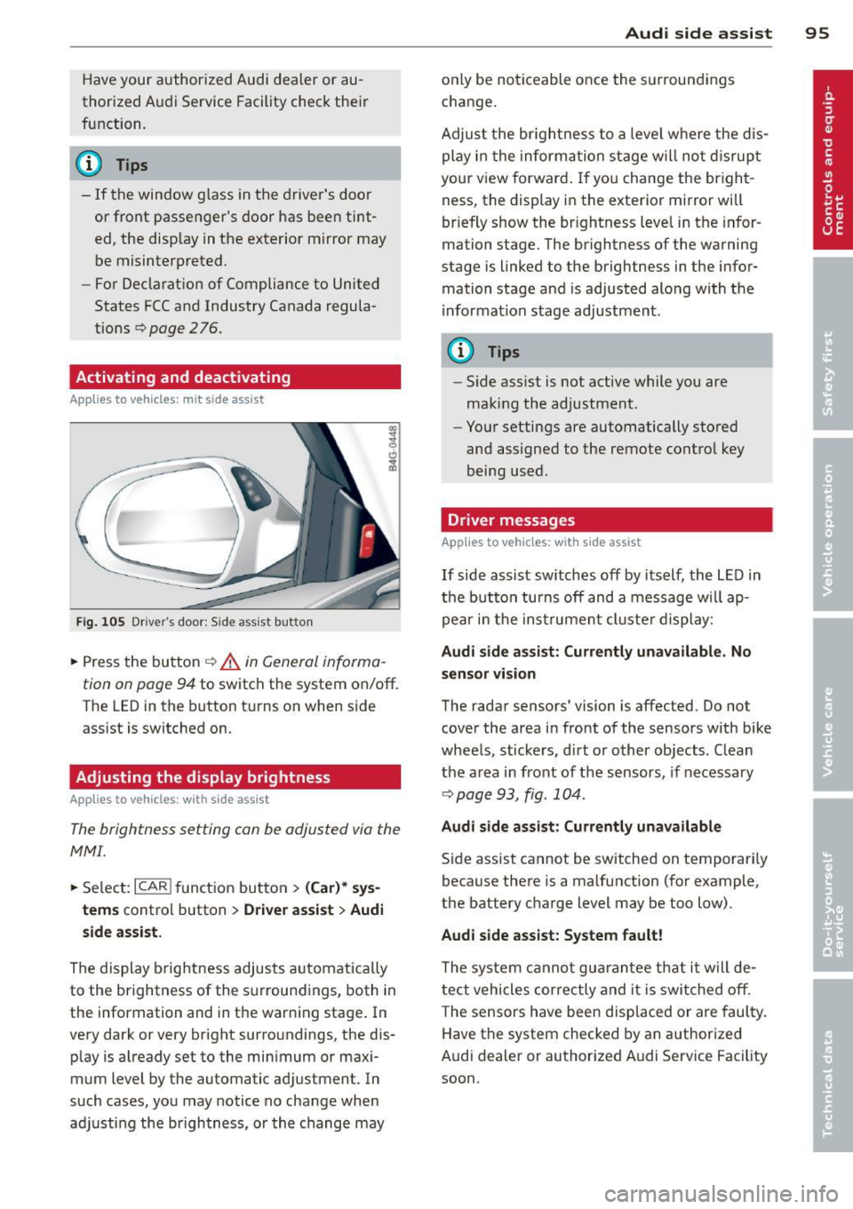
Fig. 10 5 Drive r's d oor : Sid e ass is t butt on
.. Press the but ton ¢ .&. in General informa
tion on page 94
to switch the system on/off .
The LED in the button t urns on when side
ass ist is switc hed on.
Adjusting the display brightness
Applies to vehicles: with side assist
The brightness setting can be adjusted via the
MMI.
.. Se lect : ICAR I function button> (Car)* sys
tems
contro l button > Drive r assist > Audi
side assist.
The display brig htness adjusts a utomatically
to the brightness of the surroun dings, both in
the information and in the warn ing stage . In
very dark or very bright surro undings, the dis
p lay is a lready set to the min imum or maxi
mum Level by the automatic ad justment. In
such cases, you may notice no cha nge when
a d ju sting the brightness, or the change may
Aud i side assist 95
only be no ticeable once the s urround ings
c hange.
Adjus t the br igh tness to a leve l where the dis
play i n the informa tion stage w ill no t dis rup t
your view forward . If you change the br igh t
ness, the display in the exterior mirror will
brief ly show the br ightness leve l in the infor
mation stage. The brightness of the warning
stage is linked to the brightness in the infor
mation stage and is adjusted alo ng with the
i nfor mation stage ad justment.
(D Tips
- Side ass ist is not act ive while you are
making the adjustment .
- Yo ur settings are automatically stored
and assigned to the remote contro l key
being used.
Driver messages
Applies to vehicles: with side assist
If side assist sw itches off by i tself, the L ED in
t he b utto n turns off and a message wi ll ap
pe ar in the inst rume nt cl uste r d is play:
Audi side assist: Currently unavailable. No
sensor vi sion
The rada r sensors' vision is affected. Do not
cover the area in fro nt of the sensors with bike
whee ls, sticke rs, d irt o r other objects. Clean
the a rea in front of the sensors, if necessary
¢page 93, fig . 10 4.
Audi side assist: Currently unavailable
Side assist cannot be switched on temporari ly
because there is a malfunction (for example,
the battery c ha rge level may be too low) .
Audi side assist: System fault !
The sy stem cannot gu arant ee th at it w ill de
tect vehicles correctly and it is swi tched o ff.
T he sensors have been disp laced or are faul ty .
Have the system checked by an authorized
A udi dealer or authorized A udi Service Facility
soon.
Page 264 of 292
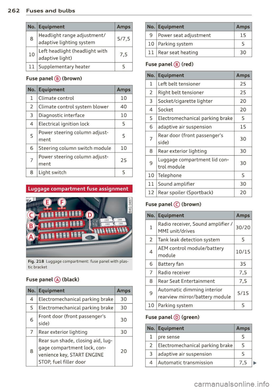
262 Fuses and bulb s
No. Equ ipment Amps
8
Headlight range adjustment/
5/7,S
adaptive lighting system
10 Left headlight
(headlight with
7,5
adaptive light)
11 Supplementary
heater
s
Fuse p ane l@ (b ro w n)
No . Equipment Amps
1 Climate control
10
2 Climate control system blower 40
3 Diagnostic interface
10
4 E lectrical ignition lock
s
s
Power steering column adjust-
s ment
6 Steering column switch module
10
7 Power steering column adjust-
ment
25
8 Light
switch
s
Luggage compartment fuse assignment
Fig. 218 Luggage compartment: fuse panel with plas
tic bracket
Fuse p anel @ (b la ck )
No. Equipment Amps
4 E lectromechanical parking brake 30
s Electromechanical parking brake
30
6 Front door
(front passenger's
30
s ide)
7 Rear exter ior lighting
30
Rear sun shade, closing aid, lug-
8 gage compartment lock, con-
20
venience key, START ENGINE
STOP, fuel filler door
No. Equipment Amps
9 Power seat adjustment
15
10 Parking system
s
11 Rear seat
heating
30
Fuse pan el@ (r e d )
No . Equipment Amps
l Left belt tensioner
25
2 Right belt tensioner 25
3 Socket/cigarette
lighter
20
4 Socket 20
s Electromechanical parking brake s
6 adaptive ai r suspension 15
7 Rear door
(front passenger's
30
side)
8 Rear exterior lighting 30
9 Luggage compartment
lid con-
30
t rol modu le
10 Telephone
s
11 Sound amplifier 30
12 Rear
spoiler (Sportback)
20
Fuse pan el© (brown)
No . Equipment Amps
1 Radio
receiver, Sound amplifier/
30/20
MMI unit/drives
2 Tank leak detection system
s
4 AEM
control module/battery
10/15
module
6 Battery fan 35
7 Rad
io receiver 7,S
8 Rear Seat Entertainment 7,5
9 Automatic d
imming interior
5/15
rearview mirror/battery module
10 Parking system
s
Fuse pan el@ (gre en)
No . Equipment Amps
1 pre sense s
2 Electromechanical parking brake s
3 adaptive
air suspension 5
4 Automatic transmission 7,5