2014 AUDI RS7 SPORTBACK tire pressure
[x] Cancel search: tire pressurePage 254 of 292
252 What do I do now?
(D Note
Do not use commerc ia lly available tire
sealants . The electrical components of the
tire pressure mon itoring system will no
longer work properly.
@ For the sake of the environment
Used sealant bottles can be dropped off at
a recycl ing facility.
@ Tips
- If sealant has run out, allow it to dry.
Then you can peel it off.
- Have the tire sealant replaced every 4
years at a dea lership.
Preliminary steps
Some preliminary steps ore necessary for tire
repair.
.,. If you have a fla t t ire, park the veh icle as far
as possible from moving traffic.
.,. Apply the
parking brake firmly .
.,. Move the
selector lever to the P position .
.,. Check whether a repair using the Tire Mobili
ty System is possible Q page 251, General
and safety pointers .
.,. Have all passengers leave the vehicle and
stay away from the danger zone
q ,& .
.,. Take the s ealant bottle and the electric air
pump
from the luggage compartment un
der the floor.
.,. Remove the "max . SO mph" (80 km/h) stick
er from the sealant bottle and aff ix it to the
instrument cluster in the driver's view .
A WARNING
-Turn the hazard flashers on and set up
the warning triangle* if you have a flat
tire in moving traffic. In this way you pro
tect you rs elf and other road users .
- Make sure that all passengers are in a
safe place, out of the danger zone (for
example, behind a guard ra il).
-
(D Note
Particular care is necessary if you are mak
ing a tire repa ir on a steep incl ine.
@ Tips
Obey all laws.
Making a tire repair
Tire repair consists of the following sections.
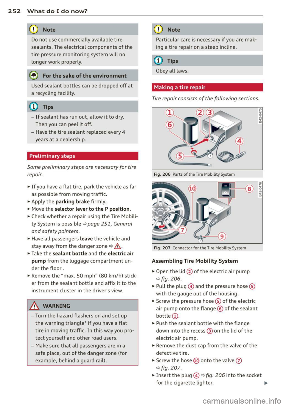
Fig. 206 Parts of t he Tire Mob ility System
Fig. 207 Co nn ector for the Tire Mobility Sys tem
Assembling Tire Mobility System
.,. Open the lid @of the electric air pump
qfig. 206.
.,. Pull the plug @and the pressure hose ®
with the gauge out of the housing .
.,. Screw the pressure hose ® of the electric
air pump onto the flange ® of the sealant
bottle @.
.,. Push the sealant bottle w ith the flange
down into the recess@ on the lid of the
electric air pump .
.,. Remove the d ust cap from the valve of the
defective tire .
.,. Screw the hose@) onto the valve
(J)
qfig. 207 .
.,. Insert the plug@¢ fig. 206 into the socket
for the cigarette lighter.
IJJ,
Page 255 of 292
~ Switch on the ignition.
Inflating tire
~ Move the sw itch @ c:> fig. 207 on t he e lec
t ric air pump
ll to posi tion I. After 5 mi
nutes, t ire press ure mus t have reac hed at
l east 1.8 ba r.
~ Switch the electric air pump off -switch in
position
0 . If the requi red tire p ressure of at
least 1.8 bar has not been reached, follow
the instructions in t he section
Re-inflating
tire.
Re -inflating tire
~ Remove the hose from the valve and p ull the
pl ug out of the soc ket .
~ Drive the vehicle s low ly 33 feet (10 meters)
backward or forward. Th is helps to distrib
ute the sealant better.
~ Remove the empty inflat ion bott le and
screw t he hose ®
c:> fig. 206 from the elec
t ric pump directly onto the va lve.
~ Inse rt the plug @ c:> fig. 206 into the so cket
f o r t he cig arette lighter.
~ Switch on the igni tion.
~ Move the sw itch @ c:>fig . 207 on the e lec
tric ai r pump
ll to positio n I. After 5 mi
nutes, t ire pressure must have reached at
least 1.8 bar.
~ Switch the electric a ir pump off - switch in
pos itio n
0. If the requ ired t ire pressu re of at
least 1.8 ba r has not been reached, it is not
poss ib le to make a repa ir with t he tire seal
an t. Seek profession al ass istance.
Disassembling Tire Mobility System
~ Remove the hose from the valve and pu ll the
plug out of the socket .
~ Screw the dust cap onto the va lve .
~ Pla ce the emp ty sealant bottle ba ck in the
o rigi nal packag ing and clip i t in place unde r
the floor so that no tire sealant can r un out
into the vehicle.
~ Place the elect ric a ir pump in the luggage
compartment fo r the time being .
l) The e lectr ic a ir pu m p sh oul d never r un for long er than
6 min utes.
What do I do now? 253
~ S tart driving rig ht away so tha t the sealant
is dist ributed in the tire .
A WARNING
- Follow the manufacturer 's sa fety instruc
tions on the decal for the air p ump and
the sealant bottle.
- If a tire pressure of 1.8 bar cannot be
achieved after pumping for S minutes,
the t ire is too severe ly damaged . Do not
con tinu e to dr ive .
- Seek pro fessional assistance if it is not
possible to repa ir the tire w ith the t ire
sealant.
(D Tips
- Do not operate the electric air pump for
more than 6 minutes witho ut stopping,
otherwise it can overheat . When the a ir
pump has coo led down, you can continue
to use it.
- If sea lant has escaped, allow it to dry,
t hen yo u can peel it off .
Final check
After driving for a short distance, tire pressure must be checked
~ A ft er driving for about 10 mi nutes, stop and
check the tire pressure.
~ If tire pressure is st ill at least 1.3 bar, in
flate the tire to specif ied p ress ure (see dr iv
er's side B-pillar), drive to the next repa ir
sh op and have t he tire and the sealant bot
tle replaced .
~ If tire pressu re is less than 1.3 bar, the tire
is too severely damaged. Do not cont inu e to
dr ive . See k professiona l as sistan ce.
A WARNING
If tir e press ure is less th an 1.3 bar a fter
d riving for 10 minutes, the t ire is too se
ve rely damage d. Do not cont in ue to drive .
Seek professional ass istance .
-
•
•
Page 257 of 292
11. Deactivate the vehicle jack mode* in the
MMI:
! CARI function button> (C ar)* sys
tem s
control button > Servicing & chec ks
> Air susp. : jack mo de> Off .
The vehicle jack mode* switches off automati
cally at speeds above 6 mph (10 km/h).
A WARNING
Always read and follow all WARNINGS and
information
c:> .&. in Raising the vehicle on
page 257
and c::> page 259.
After changing a wheel
A wheel change is not complete without the
doing the following .
.. Always store the vehicle tool kit, the jack*
and the replaced tire in the luggage com
partment
c::> page 129.
.. As soon as possible, have the tighten ing
torqu es
on all wheel bolts checked with a
torque wrench . The correct tightening tor
que is 90 ft lb (120 Nm) .
.. Have the flat tire
re pl ace d as soon as poss i
ble.
@ Tips
- If you notice that th e whee l bolts are
corroded and difficult to turn wh ile
changing a t ire, they should be replaced
before you check the tighten ing torque .
- Drive at reduced speed unt il you have the
tightening torq ues checked .
- After changing a wheel, the tire pressure
i n a ll four tires must be checked/cor rect
ed and the tire pressure mon itoring indi
cator must be stored in the MM I
c::>page248 .
What do I do now ? 255
Wheels with wheel bolt caps
Applies to vehicles: with wheel bolts with caps
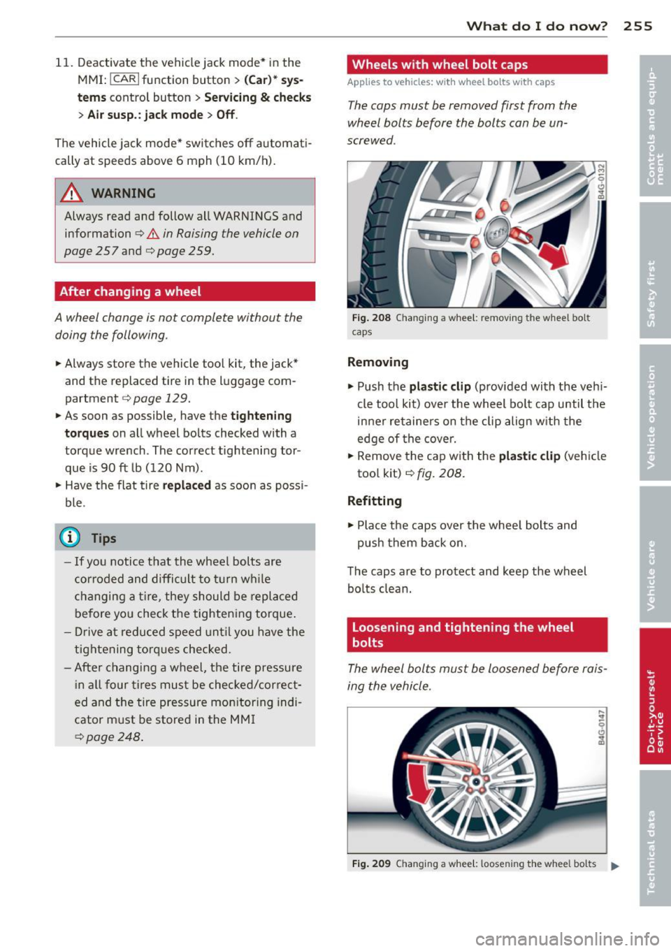
The caps must be removed first from the
wheel bolts before the bolts can be un
screwed .
Fig. 208 C hanging a whee l: removi ng the wheel bo lt
caps
Removing
.. Push the pla stic clip (provided with the veh i
cle too l kit) over the wheel bo lt cap until the
inner retainers on the clip align w ith the
edge of the cove r.
.,. Remove the cap with the
plas tic clip (ve hicle
too l kit)
c::> fig. 208 .
Refitting
.,. Place the caps over the whee l bolts and
push them back on.
The caps are to protect and keep the wheel bolts clean.
Loosening and tightening the wheel
bolts
The wheel bolts must be loosened before rais
ing the vehicle.
Fig. 209 Changing a wheel: loosening t he wheel bolts ..
Page 261 of 292

Tires with unidirectional tread design
Tires with unidirectional tread design must be
mounted with their tread pattern pointed in the right direction .
Using a replacement tire with a tre ad
patte rn intend ed for us e in a specific
directi on
When us ing a replacement t ire with a tread
pattern intended for use in a specific direc
tion, please note the fo llowing :
- T he direction of rotation is marked by an ar
row on the side of the tire .
-If the replacement tire has to be installed in
t h e incorrect d irection, use the rep lacement
t ire only temporarily since the t ire will not
be able to achieve i ts optimum performance
characteristics with regard to aquap laning,
noise and wear .
- We recommend that you pay particular at
tention to this fact during wet weather and
that you adjust your speed to match road conditions .
- Replace the flat tire with a new one and
have it installed on you r veh icle as soon as
poss ible to restore the handling advantages
of a unid irect ional tire.
Notes on wheel changing
P lease read the information ¢ page 239, New
tires and replacing tires and wheels
i f you are
go ing to use a replacement tire w hich is dif
fe rent from the tires on your vehicle.
After you change a ti re :
- Chec k the tir e p ress ure on the rep lacement
t ire immed ia tel y aft er in stall ation.
- Ha ve the wheel bolt tight ening torque
checked w ith a to rqu e wrench as soon as
possible by your auth oriz ed Aud i dealer o r
a qu alifi ed s erv ice station .
- With steel and allo y wheel rims , the wheel
bol ts are correctl y tightened at a to rque of
9 0 ft lb (1 20 Nm ).
- If y ou no tice th at the whee l bolts are cor
roded and d ifficult to tu rn whil e cha nging
What do I do now? 259
a tire , th ey s hould be repl aced before you
c heck the tightening torq ue.
- Repl ac e th e flat ti re with a new on e and
ha ve it in sta lled on you r veh icle as s oon a s
po ssible. Remount the whee l cove r.
Until then , dri ve with extr a care and at r e
du ced sp ee ds.
A WARNING
-=
- If you are going to equip your vehicle
with tires or rims which differ from those
which were factory installed, then be sure to read the information ¢
page 239,
New tires and replacing tires and
wheels .
-Always make sure the damaged wheel or
even a flat tire and the jack and tool kit
are properly secured in the luggage com
partment and are not loose in the pas
senger compartment .
- In an accident or sudden maneuver they
co uld fly forwa rd , injuring anyone in the
veh icle.
- Always sto re damaged wheel, jack and
too ls securely in the luggage compa rt
men t. Othe rwise , in an accident or s ud
den maneuver they co uld f ly forward ,
causing injury to passengers in the vehi
cle.
([) Note
Do not use commercially avai lab le tire
sea lants . O therwise, the e lectr ica l compo
nents of the tire pressure monitoring sys
tem will no longer work properly and the
sensor for the tire pressure mon itor ing
system will have to be rep laced by quali
fied workshop. •
•
Page 263 of 292

No. Equ ipment Amps
4 Suspension control system sen-s sor
s
E
lectronic Stabilization Cont rol
s (ESC) module
6 Climate control
5
7 Adaptive cruise control 10
8
Airbag control module, front
5
passenger's seat sensor system
9 Gateway 5
Homelink (garage doo r opener),
10 night vis ion system cont ro l 5
module
11 Image
processing (active lane
10
ass ist, adaptive cruise control)
12 Dynamic steering 5
13 Terminal 15 in
the instrument
15
panel
14 Terminal 15
in the luggage com-
partment 30
15 Terminal 15
(engine)
15
16 Starter 40
Fu se pa nel ® (b rown )
No . Equipment Amps
1 Gateway
5
2 C limate control 10
3 E
lectronic Stabili zation Contro l
10
(ESC) module
4 Fron
t door (driver 's side)
30
s
Power seat adjustment (driver's
7,5
seat)
6 Dynam
ic steering
35
7 Sunroof 20
8
Rear door control module (driv-
15
er 's side)
9 Lumbar support (
Front passen-
s ger seat)
10 Tire pressure
monitoring system
5
11 Su
nroof, rear spoi ler (Sportba ck)
20
12 Driver
door control module
15
Fuse s and bulb s 261
Fuse pan el© (r e d )
No . Equipment
2 Fuel pump
3 Brake light sensor/brake pedal
sensor system
AdBlue control module (Diesel)/
4 Engine acoust ics
5 Left rear door cont rol modu le
6 Power seat adjustment
(pas-
senge r's seat)
7 Horn
8 Windshield wiper motor
9 Light/rain sensor, heater
for vid-
eo camera in windscreen
10 L umba r support (driver seat)
1 1 Front
passenger door control
modu le
12 Right rea r door cont rol modu le
Front passenger side cockpit fuse
assignment Amp
s
25
5/5
5/7,S 30
7,5 15
30
s
5
15
15
F ig . 217 Front passenger side cockpit: fuse pa nel w it h
plast ic brac ket
Fuse panel @ (bla ck)
No . Equipment Amps
1 Head-up
Display
5
2 MMI Display 5
3 CO/DVD changer
5
4 MMI unit/drives 7,5
5 Chip
card reader (not in all coun-
5
tries)
6 Instrument
cluster
5
7 Steering column switch module 5 ...
Page 270 of 292
268 Emergency situations
@ Tips
Check carefully to make sure the hook-up
is secure before moving the car up the flat
bed truck ramp.
Vehicle transport
Whenever you have your vehicle transported,
be sure to note the following:
(D Note
Mount the tie-down chains/cables over the
running surface (circumference) of the
tires. Never secure the vehicle by the axle,
the suspension struts or the front or rear
towline eye. For technical reasons, the
pressure in the suspension struts may
change during the transport and this will
adversely affect vehicle handling.
Lifting vehicle
Lifting with workshop hoist and with
floor jack
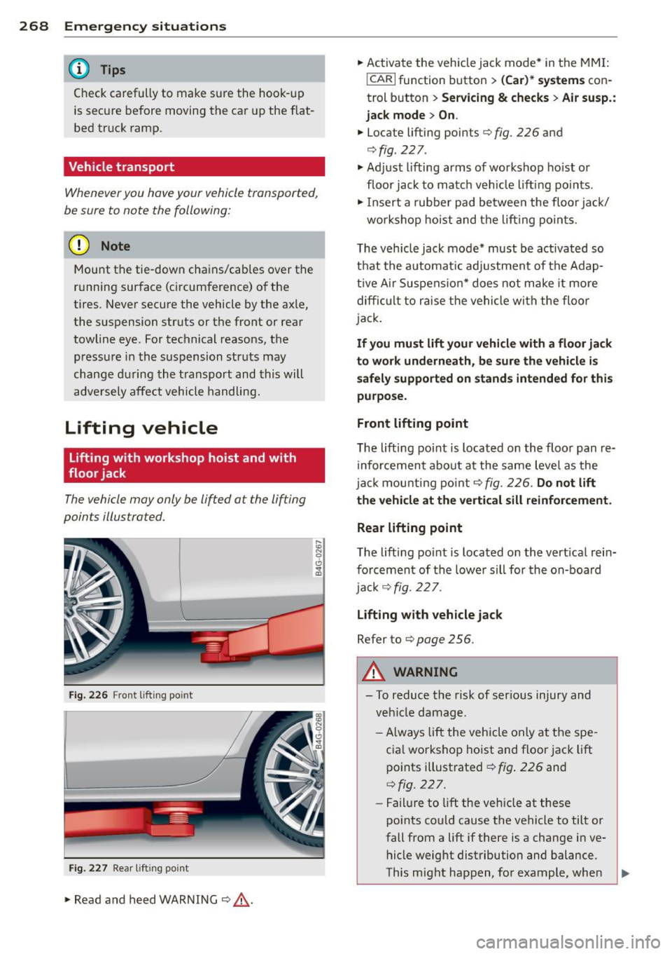
The vehicle may only be lifted at the lifting
points illustrated.
Fig. 226 Front lift in g po int
Fig. 227 Rear lifti ng point
.,. Read and heed WARNING¢&, .
~ N 0 6 .., (0
... Activate the vehicle jack mode* in the MMI:
!CARI function button > (Car)* systems con
trol button>
Servicing & checks> Air susp.:
jack mode > On.
... Locate lifting points ¢ fig . 226 and
¢fig . 227 .
.,. Adjust lifting arms of workshop hoist or
floor jack to match veh icle lifting points .
.,. Insert a rubber pad between the floor jack/
workshop hoist and the lifting points .
The vehicle jack mode* must be activated so
that the automat ic adjustment of the Adap
tive Ai r Suspens ion* does not make it more
difficult to raise the vehicle with the floor
jack .
If you must lift your vehicle with a floor jack
to work underneath, be sure the vehicle is
safely supported on stands intended for this
purpose.
Front lifting point
The lifting point is located on the floor pan re
inforcement about at the same level as the
jack mounting point
¢fig. 226. Do not lift
the vehicle at the vertical sill reinforcement .
Rear lifting point
The lifting point is located on the vert ical rein
forcement of the lower sill for the on-board
jack
c!;> fig. 2 2 7.
Lifting with vehicle jack
Refer to¢ page 256 .
A WARNING
-To reduce the risk of ser ious injury and
veh icle damage.
- Always lift the vehicle only at the spe
cial workshop hoist and floor jack lift
points illustrated¢
fig. 226 and
¢ fig. 227.
-Failure to lift the veh icle at these
points could cause the vehicle to tilt or
fall from a lift if there is a change in ve
hicle weight distribution and balance.
This might happen, for example, when
-
Page 278 of 292
2 76 Consumer Information
This will help ensure that vehicle function,
performance and safety are not impaired
c:::> &. .
Attempting to work on electronic components
and the software used with them can cause
malfunctions. Because of the way electronic
components are interconnected with each
other, such malfunctions can also have an ad
verse affect on other systems that are not di rectly involved . Th is means that you risk both
a substantial reduction in the operational
safety of your vehicle and an increased wear of
vehicle pa rts
c:::> &. .
Author ized Audi dealers will perform this
work in a p rofessional and competent manner
or, in special cases, refer you to a professional
company that specializes in such mod ifi ca
tions.
& WARNING
Improper repairs and modifications can
change the way vehicle systems work and
cause damage to the vehicle and serious
personal injury.
-
(D Note
If emergency repairs must be performed
elsewhere, have the vehicle examined by
an authorized Audi dealer as soon as possi
ble.
Declaration of
Compliance, Telecom
munication and
Electronic Systems
Radio Frequency Devices and Radiocommuni
cation Equipmen t User Manual Notice.
The manufacturer is not responsible for any
radio or TV interference caused by unauthor
ized modifications to this equipment.
Devices
The following devices each comp ly with FCC
Part 15.19, FCC 15.21 and RSS-Gen Issue 1:
- Adaptive cruise control* -
Audi side assist*
- Cell phone package*
- Convenience key*
- Electron ic immobilizer
- Homelink un iversal remote control*
- Remote control key
- Tire pressure monitoring system
FCC Part 15.19
Th is device complies with part 15 of the FCC
Ru les . Operation is subject to the following
two conditions :
(1) This device may not cause harmful inter
ference, and
(2) this device must accept any interference
received, including interference that may
cause undesired operation .
FCC Part 15.21
CAUTION:
Changes or modifications not expressly ap
proved by the party responsible for compli
ance could void the user's authority to operate
the equipment.
RSS-Gen Issue 1
Operation is subject to the following two con
ditions:
(1) this device may not cause interference ,
and
(2) this device must accept any interference ,
including interference that may cause unde
s ir ed operation of the device.
Page 280 of 292

278 Index
Setup . . . . . . . . . . . . . . . . . . . . . . . . . . . . 72
synchronizing ............. ... .... .. 71
Automatic Shift Lock (ASL) .......... . 105
Automatic transmission . . . . . . . . . . . . . . 104
Automatic Shift Lock (ASL) . .. .. .. .. . 105
Driving .... .. ........ .... ... .. .. . 106
Emergency mode ........... .. .. ... 108
E mergency release ........ .. .. .. .. . 109
Kick -down ............... .... .... . 108
Manual shift program ......... .. .. . 108
Selector lever ............. ... .... . 104
Automatic wipers . .. ........ ... .. .. .. 48
Auto Safety Hotline . . . . . . . . . . . . . . . . . 131
Average consumption ....... .. .. .. .. . . 24
Average speed . . . . . . . . . . . . . . . . . . . . . . . 24
Avoid damaging the vehicle ........ .. . 199
B
Bag hooks . . . . . . . . . . . . . . . . . . . . . . . . . . 67
Battery ... .. .. .. ............ ... .. . 223
Charging ... .. .. .. .......... ... .. . 226
I mportant warnings ...... .. .. .. .. . 224
Jump starting .. ........ .. .. .. .. .. . 264
L ocat ion ..... ........... ........ . 224
l ow ... .... ................ ..... . 195
Rep lacing the battery ...... ... .. .. . 227
State of charge ............ ... .. .. . 195
Winter operation ......... .... .... . 223
Working on the battery .... .. .. .. .. . 224
Before driving . . . . . . . . . . . . . . . . . . . . . . 123
Blended gasoline .... ...... .. .. .. .. . 208
Blower (automatic climate control) . . . . . . 71
Boost display . . . . . . . . . . . . . . . . . . . . . . . . 28
Booster seats ... .... ...... .. .. .. .. . 177
Boost pressure indicator .......... .. .. 28
Brake fluid Changing the brake fl uid ... .... .. .. . 223
Check ing the brake fluid level . .. .. .. . 222
What is the correct brake fluid leve l? .. 222
What should I do if the brake fluid warn-
ing light comes on? ........ .... ... . 222
Brake system Anti-lock braking system ..... .. ...... 19
Brake assist system ........ ... .. .. . 189
Brake booster ............. ... .... . 193
Brake fluid ............... ... .... . 222 Brake fluid specifications for refill and re
placement
. . . . . . . . . . . . . . . . . . . . . . . 223
Brake light defective . . . . . . . . . . . . . . . . 21
Brake pads ...... ............. .... 198
Electromechanical parking brake . .... . 77
Fluid reservoir . .. ................ . 222
How does moisture or road salt affect the
brakes? ....... .. .. ........ ... ... . 193
Warning/ind icator lights ...... .. .. .. . 14
Worn b rake pads symbo l ........ .. .. . 20
braking guard
Settings . . . . . . . . . . . . . . . . . . . . . . . . . . 88
Braking guard ..... ............. ... .. 81
Messages . .. .. .. .. ........... .... . 88
Break-in per iod .... ............. .... 198
Brake pads .... .. ................ . 198
Tires .... ..... .. .. .............. . 198
Bu lbs .. .. .. .. .. .. .. .. ...... ... .. .. 263
C
California Proposition 65 Warn ing .... . 214
Battery specific .. ..... ......... ... 225
Capacities .. .... .. ................. 271
Engine oil ....... ............. .... 215
Carbon parts Cleaning . . . . . . . . . . . . . . . . . . . . 205, 206
Car carrier Transporting your vehicle ....... .. .. 268
Care ... .. .. .. .. .. ............. .. .. 203
Cargo area . ..... .. ............. ... . 129
Cargo net . . . . . . . . . . . . . . . . . . . . . . . . . . . 66
Catalytic converter .............. .. .. 199
Center armrest Cockpit . . . . . . . . . . . . . . . . . . . . . . . . . . . 56
Central locking .. .. .......... ...... .. 34
Emergency locking ... ....... ...... .. 38
Certification ..................... .. 276
Changi ng a wheel .. ... .......... .. .. 254
Changing engine oil .......... ...... . 219
Checking Engine coolant level ............ .... 220
Tire pressure ... .. ... .......... .. .. 234