2014 AUDI RS7 SPORTBACK radio
[x] Cancel search: radioPage 248 of 292

246 Tires and wheels
Refer to ¢page 243 for mo re detailed infor
mation regarding winter tires .
Tire pressure
monitoring system
(D General notes
Each tire, including the spare (if provided) ,
should be checked monthly when cold and in
flated to the inflation pressure recommended by the vehicle manufacturer on the vehicle
placard or tire inflation pressure label. (If your
vehicle has tires of a different size than the
size indicated on the vehicle placard or tire in
flation pressure label, you shou ld determine
the proper tire inflation pressure for those
tires).
As an added safety feature, your vehicle has
been equipped with a tire pressure monitor ing
system (TPMS) that illuminates a low tire
p ressure telltale when one or more of your
tires is significantly under-inflated. According
ly, when the low tire pressure telltale illumi
nates, you should stop and check your tires as
soon as possible, and inflate them to the proper pressure. Driving on a significantly un
der-inflated tire causes the tire to overheat
and can lead to tire failure . Under -inflation al
so reduces fuel efficiency and tire tread life,
and may affect the vehicle's handling and
stopping ab ility.
Please note that the TPMS is not a subst itute
for proper tire maintenance, and it is the driv
e r's responsib ility to ma inta in correct tire
pressure, even if under-inflation has not
reached the level to trigger illumination of the
TPMS low tire pressure telltale.
Your veh icle has also been equ ipped w ith a
TPMS malfunction indicator to indicate when
the system is not operating properly. The
TPMS malfunction indicator is combined with
the low tire pressure telltale . When the sys
tem detects a malfunction, the te lltale will
flash for approximately one minute and then remain continuously illuminated. This se- quence will continue upon subsequent vehicle
start-ups as
long as the malfunction exists.
When the malfunction indicator is illum inat
ed, the system may not be ab le to detect or
signal low tire pressure as intended . TPMS
malfunctions may occur for a variety of rea
sons, including the installation of replace
ment or alternate tires or wheels on the vehi
cle that prevent the TPMS from functioning
properly. Always check the TPMS malfunction
telltale after replacing one or more tires or
wheels on your vehicle to ensure that the re
placement o r alternate ti res and wheels allow
the TPM S to cont inue to function properly.
Description
The tire pressure monitoring system monitors
the pressure in the four tires when driving.
The system uses sensors that measure the
temperature and pressure in the tires. Theda
ta is sent from these sensors to the control
module by radio frequency.
The tire pressure monitoring system shows
the current pressures and temperatures of the
tires in the Infotainment system
¢page 247.
It also compares the current tire pressures
with the stored pressures and gives a warning in the driver information system if the tire
pressure is different from what is stored
¢ page 247.
The system does not detect if the stored tire
pressures match the recommended tire pres
sures. You must resave the tire pressures
¢page 248:
- eve ry time the tire p ressu res change, for ex
ample when the load in the vehicle changes,
- after replacing a t ire, or
- if wheels w ith new wheel sensors are used .
_&. WARNING
-The tire pressu re monitoring sys tem as
sists the driver in monitoring tire pres
sures. The driver is responsible for having
the tires inflated to the correct pressure. ..,.
Page 264 of 292
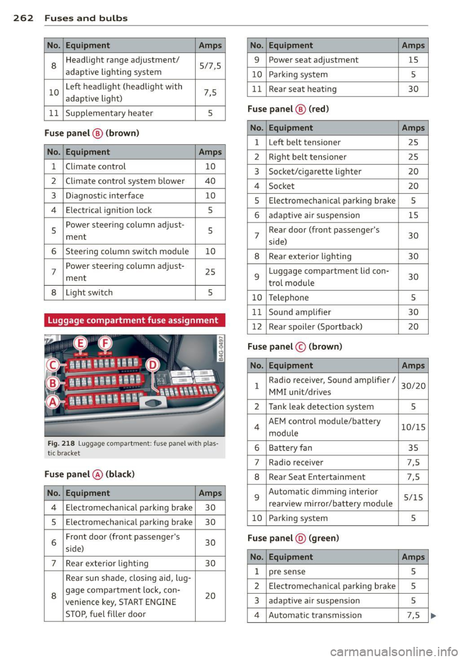
262 Fuses and bulb s
No. Equ ipment Amps
8
Headlight range adjustment/
5/7,S
adaptive lighting system
10 Left headlight
(headlight with
7,5
adaptive light)
11 Supplementary
heater
s
Fuse p ane l@ (b ro w n)
No . Equipment Amps
1 Climate control
10
2 Climate control system blower 40
3 Diagnostic interface
10
4 E lectrical ignition lock
s
s
Power steering column adjust-
s ment
6 Steering column switch module
10
7 Power steering column adjust-
ment
25
8 Light
switch
s
Luggage compartment fuse assignment
Fig. 218 Luggage compartment: fuse panel with plas
tic bracket
Fuse p anel @ (b la ck )
No. Equipment Amps
4 E lectromechanical parking brake 30
s Electromechanical parking brake
30
6 Front door
(front passenger's
30
s ide)
7 Rear exter ior lighting
30
Rear sun shade, closing aid, lug-
8 gage compartment lock, con-
20
venience key, START ENGINE
STOP, fuel filler door
No. Equipment Amps
9 Power seat adjustment
15
10 Parking system
s
11 Rear seat
heating
30
Fuse pan el@ (r e d )
No . Equipment Amps
l Left belt tensioner
25
2 Right belt tensioner 25
3 Socket/cigarette
lighter
20
4 Socket 20
s Electromechanical parking brake s
6 adaptive ai r suspension 15
7 Rear door
(front passenger's
30
side)
8 Rear exterior lighting 30
9 Luggage compartment
lid con-
30
t rol modu le
10 Telephone
s
11 Sound amplifier 30
12 Rear
spoiler (Sportback)
20
Fuse pan el© (brown)
No . Equipment Amps
1 Radio
receiver, Sound amplifier/
30/20
MMI unit/drives
2 Tank leak detection system
s
4 AEM
control module/battery
10/15
module
6 Battery fan 35
7 Rad
io receiver 7,S
8 Rear Seat Entertainment 7,5
9 Automatic d
imming interior
5/15
rearview mirror/battery module
10 Parking system
s
Fuse pan el@ (gre en)
No . Equipment Amps
1 pre sense s
2 Electromechanical parking brake s
3 adaptive
air suspension 5
4 Automatic transmission 7,5
Page 266 of 292
264 Emergency situations
Emergency situations
General
This chapter is intended for trained emer
gency crews and working personnel who
have the necessary tools and equipment to
perform these ope rations.
Starting by pushing or
towing
Q;) Note
Vehicles w ith an automatic transmission
cannot be started by pus hing o r tow ing.
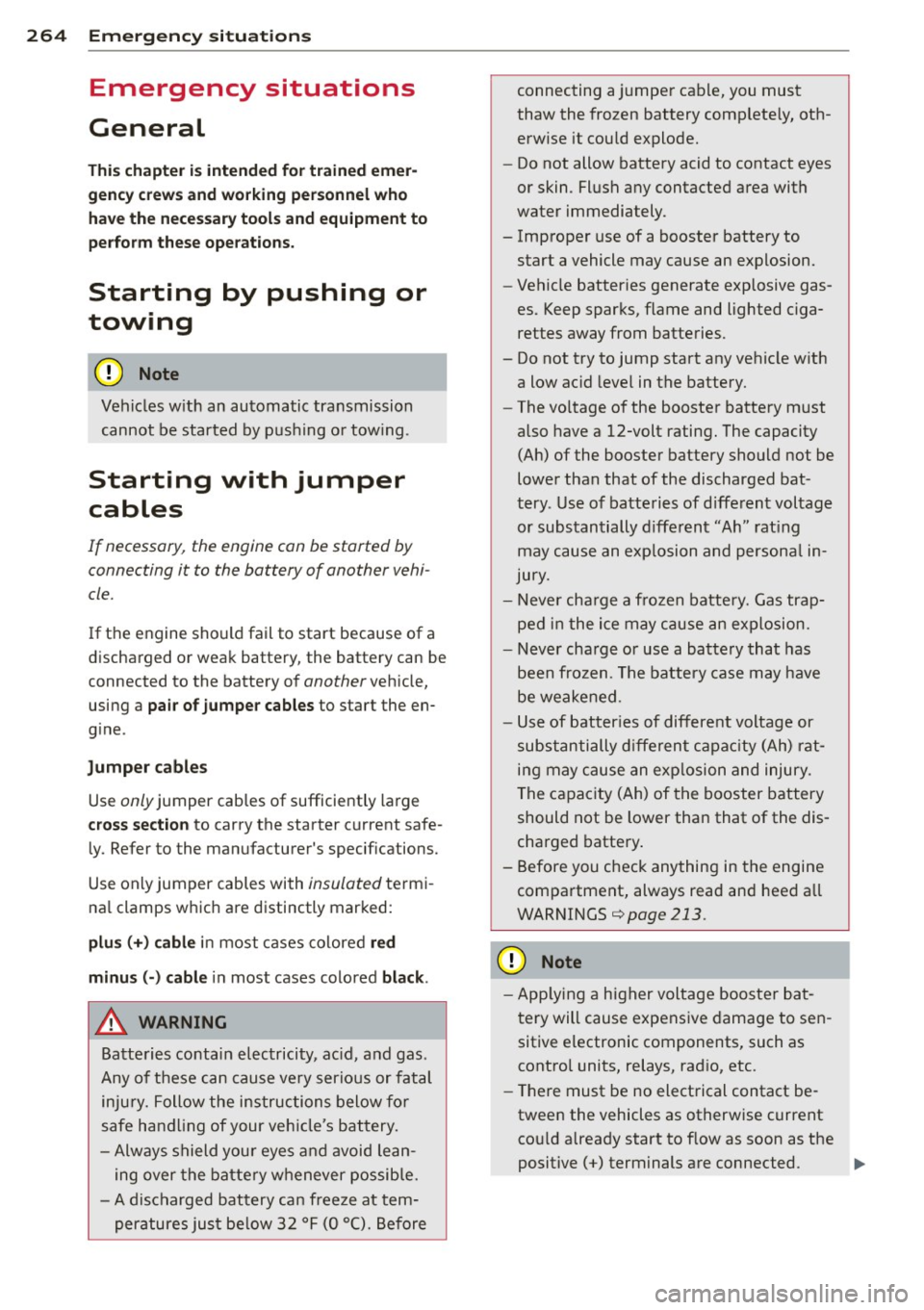
Starting with jumper
cables
If necessary, the engine can be started by
connecting it to the battery of another vehi
cle.
If the engine should fail to start because of a
discharged or weak battery, the battery can be
connected to the battery of
another veh icle,
using a
pair of jumpe r cables to start the en
g ine .
Jumper cables
Use only jumper cables of sufficiently large
cross section to carry the starter current safe
ly. Refer to the manufacturer's specif ications.
Use only jumper cables with
insulated termi
na l clamps which are distinctly marked:
plus(+) cable in most cases colored red
minu s(-) cable
in most cases colored black .
A WARNING
Batteries contain electricity, acid, and gas.
Any of these can cause very serious or fatal
inju ry. Follow the instructions below for
safe handling of your veh icle's battery.
- Always shield you r eyes and avoid lean
ing over the battery whenever possible.
- A discharged battery can freeze at tem
peratures just be low 32 °F (0 °C). Before connecting a
jumper cable, you must
thaw the frozen battery complete ly, oth
erwise it could explode.
- Do not allow battery acid to contact eyes
or skin. Flush any contacted area with
water immediately.
- Improper use of a booster battery to start a vehicle may cause an explosion.
- Vehicle batteries generate explosive gas
es. Keep sparks, flame and lighted ciga
rettes away from batteries.
- Do not try to jump start any vehicle with a low acid level in the battery.
- The vo ltage of the booster battery must
also have a 12-volt rating. The capacity
(Ah) of the booster battery should not be
lower than that of the discharged bat
tery . Use of batteries of d ifferent voltage
or substantially different "Ah" rating
may cause an exp losion and personal in
jury.
- Never charge a frozen batte ry. Gas trap
ped in the ice may cause an explosion.
- Never charge or use a battery that has
been frozen. The battery case may have
be weakened.
- Use of batter ies of different voltage or
substantially different capacity (Ah) rat
ing may cause an exp losion and injury.
The capacity (Ah) of the booster battery
should not be lower than that of the dis
charged battery.
- Before you check anything in the engine
compartment, always read and heed a ll
WARNINGS¢
page 213.
(D Note
- App lying a higher voltage booster bat
tery will cause expensive damage to sen
sitive electronic components, such as
control units, relays, radio, etc.
- Th ere must be no electrical contact be
tween the vehicles as otherwise current cou ld already start to f low as soon as the
positive(+) terminals are connected. .,.
Page 278 of 292
2 76 Consumer Information
This will help ensure that vehicle function,
performance and safety are not impaired
c:::> &. .
Attempting to work on electronic components
and the software used with them can cause
malfunctions. Because of the way electronic
components are interconnected with each
other, such malfunctions can also have an ad
verse affect on other systems that are not di rectly involved . Th is means that you risk both
a substantial reduction in the operational
safety of your vehicle and an increased wear of
vehicle pa rts
c:::> &. .
Author ized Audi dealers will perform this
work in a p rofessional and competent manner
or, in special cases, refer you to a professional
company that specializes in such mod ifi ca
tions.
& WARNING
Improper repairs and modifications can
change the way vehicle systems work and
cause damage to the vehicle and serious
personal injury.
-
(D Note
If emergency repairs must be performed
elsewhere, have the vehicle examined by
an authorized Audi dealer as soon as possi
ble.
Declaration of
Compliance, Telecom
munication and
Electronic Systems
Radio Frequency Devices and Radiocommuni
cation Equipmen t User Manual Notice.
The manufacturer is not responsible for any
radio or TV interference caused by unauthor
ized modifications to this equipment.
Devices
The following devices each comp ly with FCC
Part 15.19, FCC 15.21 and RSS-Gen Issue 1:
- Adaptive cruise control* -
Audi side assist*
- Cell phone package*
- Convenience key*
- Electron ic immobilizer
- Homelink un iversal remote control*
- Remote control key
- Tire pressure monitoring system
FCC Part 15.19
Th is device complies with part 15 of the FCC
Ru les . Operation is subject to the following
two conditions :
(1) This device may not cause harmful inter
ference, and
(2) this device must accept any interference
received, including interference that may
cause undesired operation .
FCC Part 15.21
CAUTION:
Changes or modifications not expressly ap
proved by the party responsible for compli
ance could void the user's authority to operate
the equipment.
RSS-Gen Issue 1
Operation is subject to the following two con
ditions:
(1) this device may not cause interference ,
and
(2) this device must accept any interference ,
including interference that may cause unde
s ir ed operation of the device.
Page 282 of 292
280 Index
Defrosting (windows)
automatic climate control . ... ... ... .. 71
Determining correct load limit ... .... . 236
Dimensions ................. .. .... . 271
Dimming the rearview mirror . ..... .. .. 51
Displays Cleaning . .. .......... ...... ... .. . 205
Distance . . . . . . . . . . . . . . . . . . . . . . . . . . . 24
Door/rear lid warning . . . . . . . . . . . . . . . . . 23
Doors Power child safety lock ........ .. .... 40
Driver information system Boost ... .. ............. .. .. .. ... . 28
CD/radio display . . . . . . . . . . . . . . . . . . . . 23
Door/rear lid warning . . . . . . . . . . . . . . . 23
Efficiency program . ........... .. .. .. 25
En gin e oi l tempe rature display .. .. .. . . 28
E xterior tempe rature display . .. .. .. . . 23
On -board computer . . . . . . . . . . . . . . . . . 24
Shifting indicator . . . . . . . . . . . . . . . . . . . 28
Driver seating position . . . . . . . . . . . . . . . 124
drive select ................. .. .... .. 96
adaptive air suspension/sport ... ...... 96
Adaptive dampers . . . . . . . . . . . . . . . . . . 96
Curve light . . . . . . . . . . . . . . . . . . . . . . . . 96
Engine sound .. .... ...... .. .. .. .. .. 96
Safety belt tensioner . . . . . . . . . . . . . . . . 96
Sport different ial . . . . . . . . . . . . . . . . . . . 96
Driving safely . . . . . . . . . . . . . . . . . . . . . . 123
Driving through water .......... .. ... 199
Driving time ............... ... .. .. .. 24
Duplicate key ............... .. .... .. 32
Dust filter
r e fer to Pollutant filter . . . . . . . . . . . . . . 69
Dynamic steering .......... .. .. .. .. . 194
E
Easy entry feature . . . . . . . . . . . . . . . . . . . . 7 4
Efficiency program . . . . . . . . . . . . . . . . . . . 25
Fu el economy messages . . . . . . . . . . . . . 25
Other equipment . . . . . . . . . . . . . . . . . . . 25
E lectrical accessories (sockets) . . . . . . . . . 60
Electro-mechanical power assist .. .. .. . 194
Electromechanical parking brake
Emergency braking . . . . . . . . . . . . . . . . . 78
Operation . . . . . . . . . . . . . . . . . . . . . . . . . 77 Parking ...
.... .. ............. ..... 78
Releasing and closing ............... 77
Starting assist . . . . . . . . . . . . . . . . . . . . . 78
Starting from rest . . . . . . . . . . . . . . . . . . 78
Warning/indicator lights ........ .... . 15
Electronic differential lock
Warning/indicator lights ............ . 18
Electronic differential lock (ED L) . . . . . . . 189
Warning/indicator lights ............ . 19
Elec tronic immobilizer . . . . . . . . . . . . 26, 33
E lectronic power control (EPC)
warning/indicator light .............. 20
Electronic Stabilization Control (ESC) . .. 189
Warning/indicator lights .......... .. . 18
Emergency actuation Doors ...... .. .. .. ...... ..... .. .. . 38
Power sunroof . .. ................ .. 43
Rear lid ....... .. ............. .... . 40
Emergency braking .............. .... . 78
Emergency flasher . . . . . . . . . . . . . . . . . . . 45
Warning/indicator lights ............. 22
Emergency release
Selector lever .... ............. .... 109
Emergency starting ............. ....
264
Emergency towing ................. . 266
Emergency warning triangle .......... 250
Energy management ............ .... 195
Engine Compartment .... ............. .... 215
Coolant ....... .. .. ............ ... 220
starting ....... .. .. .............. .. 74
Starting with jumper cables ....... .. 264
Stopping .. .... .. ............. .... . 75
Engine compartment ................ 215 Closing the hood .............. .... 214
Opening the hood ................ . 213
Safety instructions ............. .... 213
Working in the engine compartment .. 213
Engine coolant .... ................ . 220
Adding coolant ... ................ . 221
Checking the engine coo lant level ..... 220
Expansion tank ... ............. .. .. 220
Malfunction symbol . . . . . . . . . . . . . . . . . 15
Radiator fan ...... .............. .. 222
Temperature gauge ......... ...... .. 10
Page 286 of 292
284 Index
Opening Hood .. .... ................ ..... . 213
Power windows .................... 41
Rear lid . . . . . . . . . . . . . . . . . . . . . . . . . . . 38
Sliding/tilting sunroof ..... .. .. .... .. 42
Operate your vehicle economica lly and
minimize po llution .......... ... .... . 200
Other equipment (effic iency program) ... 25
Outlet .. .. .. ............. .. .. .. ... . 59
p
Paint damage
205
Paint No . .. .... ........... .. .. .... . 270
Parking . .. .... ........... .... .... .. 78
Automatic transmission ....... .. ... 106
Valet park ing .. ... ... .... .. .. .. .. .. 42
Parking brake ............. .. .. .. ... . 77
also refer to Electromechanical parking
br ake .. .. ................. .. .. .. .. 77
Parking system Adjusting the disp lay/warning tone . .. 120
C leaning sensors/came ra lenses . .... . 204
Cleaning the rear view camera .. .. .. .
Malfunc tion ......... ...... .. .. .. .
Parking system plus ........ ... .. .. . 112
120
111
Peripheral cameras ........ ... .. ... 115
Rear view camera ............. .. ... 11 2
o/sorefertoPark ingsystems . .. 111 ,112
Pa rking systems .. ......... .. .. .. .. . 110
Parts replacement .......... ... .... . 275
Pass-through with sk i sack ... .. .. .. .. . . 67
PASS ENG ER A IR BAG OF F light . . . . . . . . 155
Passenger protection ....... .. .. .. .. . 187
Passive safety system . . . . . . . . . . . . . . . . 123
Pedals .... .. ............... .. .... . 128
Physical principles of a frontal coll is ion 134
Plas tic parts
Cleaning . ...... .. ..... .... .. .. .. . 205
Polishing .... ................ ..... . 205
Pollen filter
refer to Pollutant filter . . . . . . . . . . . . . . 69
Pollutan t filter ............ .. .. .. .. .. 69
Power locking system . . . . . . . . . . . . . . . . . 34
Locking/unlocking the vehicle from in-
side ... .... ................ ..... .. 37
Selective unlock feature ... .. .. .... .. 35 Settings .
..... .. ............. ..... 35
Unlocking and locking vehicle ..... ... . 35
Power seat ad justment
Front seats . . . . . . . . . . . . . . . . . . . . . . . . 54
Power steer ing
refer to Electro -mechanical power as -
sist ......... ... .. ............... 194
Power windows .. ........ ....... .... . 41
malfunction . .. .. .... ... .. .. .. .. .. . 41
Pregnant women Special considerations when wearing a
safety belt .... .. ................ . 138
pre sense . .. .. .. . .. ... ..... ... ... .. 187
Preventative passenger pro tec tion . .. .. 187
Programming the Homelink universal re -
mote control . ..... ................. 121
Proper occupant seating positions . .. .. 124
Proper safe ty belt position .. .... .. .... 13 7
Proper seating position Front passenger .. ............. .... 125
Occupants ..... .. ................. 124
Rear passengers . . . . . . . . . . . . . . . . . . . 126
Protecting
Q
quattro
refer to All-wheel drive
Question What happens to unbelted occupants?
Why safety belts? ................ .
R
205
195
1 34
133
Radia tor fan .. .. .. ...... ..... .. .... 222
Radio clock . . . . . . . . . . . . . . . . . . . . . . . . . 26
Rain/light sensor Headlights .. .. .. ....... ..... ..... . 44
Inte rmittent (w indshield w ipers) . .... . 48
Sensor defective . . . . . . . . . . . . . . . . . . . . 22
Range (fuel level) . . . . . . . . . . . . . . . . . . . . 24
Reading lights ..... ............. ..... 47
Rear fog lights .. .. ... .. .. .. .. .. .. .. . 44
Rear lid
Automatic operation . . . . . . . . . . . . . . . . 38
Emergency release .................. 40