Page 17 of 228

1-7
FEATURES
FEATURES
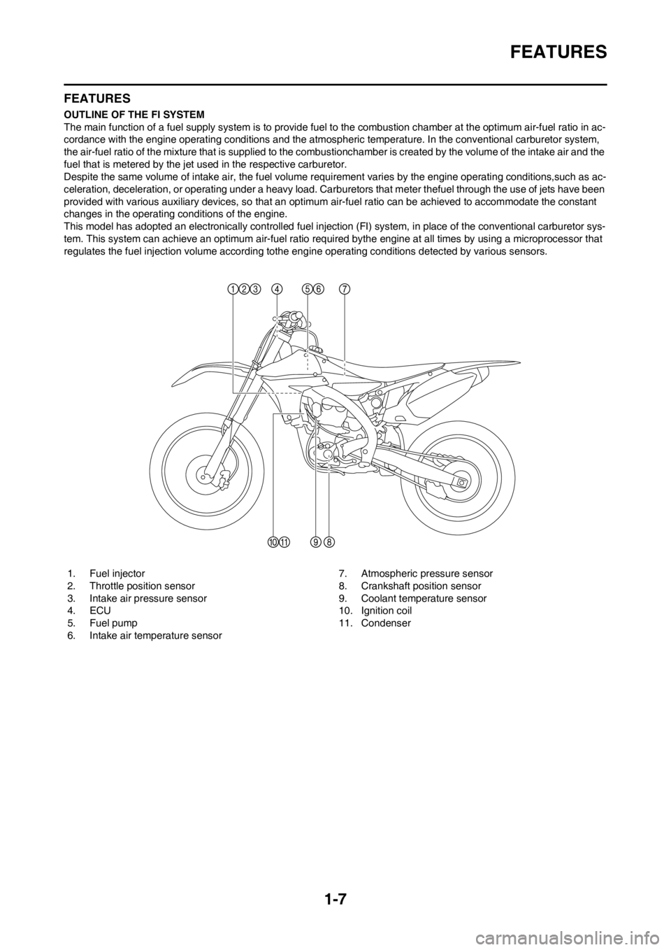
OUTLINE OF THE FI SYSTEM
The main function of a fuel supply system is to provide fuel to the combustion chamber at the optimum air-fuel ratio in ac-
cordance with the engine operating conditions and the atmospheric temperature. In the conventional carburetor system,
the air-fuel ratio of the mixture that is supplied to the combustionchamber is created by the volume of the intake air and the
fuel that is metered by the jet used in the respective carburetor.
Despite the same volume of intake air, the fuel volume requirement varies by the engine operating conditions,such as ac-
celeration, deceleration, or operating under a heavy load. Carburetors that meter thefuel through the use of jets have been
provided with various auxiliary devices, so that an optimum air-fuel ratio can be achieved to accommodate the constant
changes in the operating conditions of the engine.
This model has adopted an electronically controlled fuel injection (FI) system, in place of the conventional carburetor sys-
tem. This system can achieve an optimum air-fuel ratio required bythe engine at all times by using a microprocessor that
regulates the fuel injection volume according tothe engine operating conditions detected by various sensors.
1. Fuel injector
2. Throttle position sensor
3. Intake air pressure sensor
4. ECU
5. Fuel pump
6. Intake air temperature sensor7. Atmospheric pressure sensor
8. Crankshaft position sensor
9. Coolant temperature sensor
10. Ignition coil
11. Condenser
Page 18 of 228

1-8
FEATURES
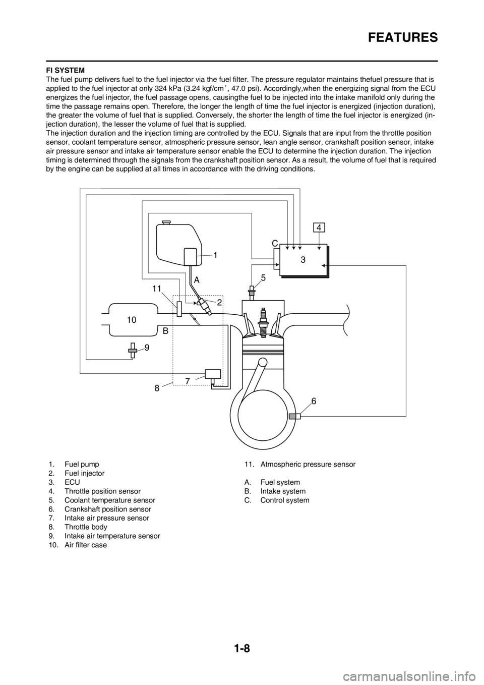
FI SYSTEM
The fuel pump delivers fuel to the fuel injector via the fuel filter. The pressure regulator maintains thefuel pressure that is
applied to the fuel injector at only 324 kPa (3.24 kgf/cm², 47.0 psi). Accordingly,when the energizing signal from the ECU
energizes the fuel injector, the fuel passage opens, causingthe fuel to be injected into the intake manifold only during the
time the passage remains open. Therefore, the longer the length of time the fuel injector is energized (injection duration),
the greater the volume of fuel that is supplied. Conversely, the shorter the length of time the fuel injector is energized (in-
jection duration), the lesser the volume of fuel that is supplied.
The injection duration and the injection timing are controlled by the ECU. Signals that are input from the throttle position
sensor, coolant temperature sensor, atmospheric pressure sensor, lean angle sensor, crankshaft position sensor, intake
air pressure sensor and intake air temperature sensor enable the ECU to determine the injection duration. The injection
timing is determined through the signals from the crankshaft position sensor. As a result, the volume of fuel that is required
by the engine can be supplied at all times in accordance with the driving conditions.
1. Fuel pump
2. Fuel injector
3. ECU
4. Throttle position sensor
5. Coolant temperature sensor
6. Crankshaft position sensor
7. Intake air pressure sensor
8. Throttle body
9. Intake air temperature sensor
10. Air filter case11. Atmospheric pressure sensor
A. Fuel system
B. Intake system
C. Control system
1
10
9B
87
6 5
A
23 C4
11
Page 19 of 228

1-9
INCLUDED PARTS
INCLUDED PARTS
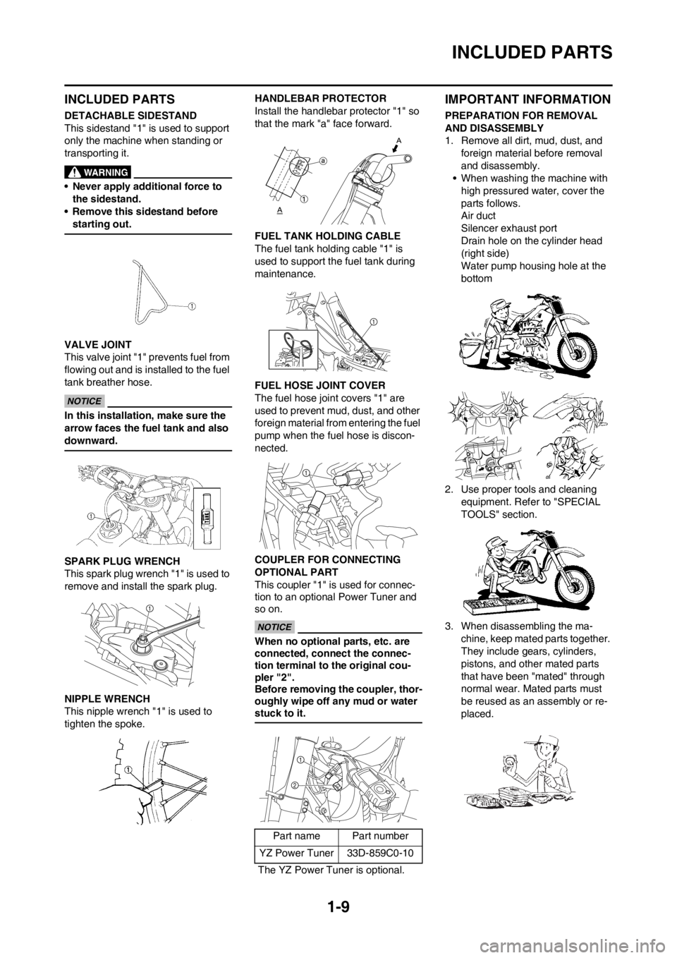
DETACHABLE SIDESTAND
This sidestand "1" is used to support
only the machine when standing or
transporting it.
• Never apply additional force to
the sidestand.
• Remove this sidestand before
starting out.
VALVE JOINT
This valve joint "1" prevents fuel from
flowing out and is installed to the fuel
tank breather hose.
In this installation, make sure the
arrow faces the fuel tank and also
downward.
SPARK PLUG WRENCH
This spark plug wrench "1" is used to
remove and install the spark plug.
NIPPLE WRENCH
This nipple wrench "1" is used to
tighten the spoke.HANDLEBAR PROTECTOR
Install the handlebar protector "1" so
that the mark "a" face forward.
FUEL TANK HOLDING CABLE
The fuel tank holding cable "1" is
used to support the fuel tank during
maintenance.
FUEL HOSE JOINT COVER
The fuel hose joint covers "1" are
used to prevent mud, dust, and other
foreign material from entering the fuel
pump when the fuel hose is discon-
nected.
COUPLER FOR CONNECTING
OPTIONAL PART
This coupler "1" is used for connec-
tion to an optional Power Tuner and
so on.
When no optional parts, etc. are
connected, connect the connec-
tion terminal to the original cou-
pler "2".
Before removing the coupler, thor-
oughly wipe off any mud or water
stuck to it.
IMPORTANT INFORMATION
PREPARATION FOR REMOVAL
AND DISASSEMBLY
1. Remove all dirt, mud, dust, and
foreign material before removal
and disassembly.
• When washing the machine with
high pressured water, cover the
parts follows.
Air duct
Silencer exhaust port
Drain hole on the cylinder head
(right side)
Water pump housing hole at the
bottom
2. Use proper tools and cleaning
equipment. Refer to "SPECIAL
TOOLS" section.
3. When disassembling the ma-
chine, keep mated parts together.
They include gears, cylinders,
pistons, and other mated parts
that have been "mated" through
normal wear. Mated parts must
be reused as an assembly or re-
placed.
Part name Part number
YZ Power Tuner 33D-859C0-10
The YZ Power Tuner is optional.
Page 20 of 228

1-10
HANDLING THE ELECTRONIC PARTS
4. During the machine disassembly,
clean all parts and place them in
trays in the order of disassembly.
This will speed up assembly time
and help assure that all parts are
correctly reinstalled.
5. Keep away from fire.
ALL REPLACEMENT PARTS
1. We recommend to use Yamaha
genuine parts for all replace-
ments. Use oil and/or grease rec-
ommended by Yamaha for
assembly and adjustment.
GASKETS, OIL SEALS AND O-
RINGS
1. All gaskets, oil seals, and O-rings
should be replaced when an en-
gine is overhauled. All gasket sur-
faces, oil seal lips, and O-rings
must be cleaned.
2. Properly oil all mating parts and
bearings during reassembly. Ap-
ply grease to the oil seal lips.
LOCK WASHERS/PLATES AND
COTTER PINS
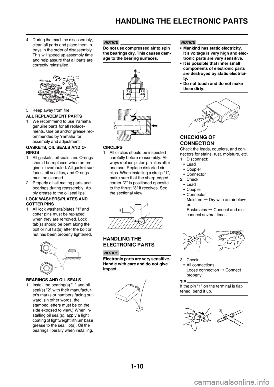
1. All lock washers/plates "1" and
cotter pins must be replaced
when they are removed. Lock
tab(s) should be bent along the
bolt or nut flat(s) after the bolt or
nut has been properly tightened.
BEARINGS AND OIL SEALS
1. Install the bearing(s) "1" and oil
seal(s) "2" with their manufactur-
er's marks or numbers facing out-
ward. (In other words, the
stamped letters must be on the
side exposed to view.) When in-
stalling oil seal(s), apply a light
coating of lightweight lithium base
grease to the seal lip(s). Oil the
bearings liberally when installing.
Do not use compressed air to spin
the bearings dry. This causes dam-
age to the bearing surfaces.
CIRCLIPS
1. All circlips should be inspected
carefully before reassembly. Al-
ways replace piston pin clips after
one use. Replace distorted cir-
clips. When installing a circlip "1",
make sure that the sharp-edged
corner "2" is positioned opposite
to the thrust "3" it receives. See
the sectional view.
HANDLING THE
ELECTRONIC PARTS
Electronic parts are very sensitive.
Handle with care and do not give
impact.
• Mankind has static electricity.
It`s voltage is very high and elec-
tronic parts are very sensitive.
• It is possible that inner small
components of electronic parts
are destroyed by static electrici-
ty.
• Do not touch and do not make
them dirty.
CHECKING OF
CONNECTION
Check the leads, couplers, and con-
nectors for stains, rust, moisture, etc.
1. Disconnect:
•Lead
• Coupler
• Connector
2. Check:
•Lead
• Coupler
• Connector
Moisture → Dry with an air blow-
er.
Rust/stains → Connect and dis-
connect several times.
3. Check:
• All connections
Loose connection → Connect
properly.
If the pin "1" on the terminal is flat-
tened, bend it up.
Page 21 of 228

1-11
CHECKING OF CONNECTION
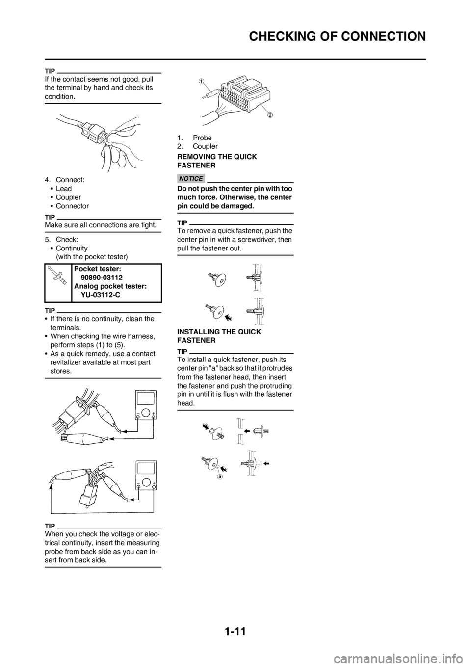
If the contact seems not good, pull
the terminal by hand and check its
condition.
4. Connect:
•Lead
• Coupler
• Connector
Make sure all connections are tight.
5. Check:
• Continuity
(with the pocket tester)
• If there is no continuity, clean the
terminals.
• When checking the wire harness,
perform steps (1) to (5).
• As a quick remedy, use a contact
revitalizer available at most part
stores.
When you check the voltage or elec-
trical continuity, insert the measuring
probe from back side as you can in-
sert from back side.
1. Probe
2. Coupler
REMOVING THE QUICK
FASTENER
Do not push the center pin with too
much force. Otherwise, the center
pin could be damaged.
To remove a quick fastener, push the
center pin in with a screwdriver, then
pull the fastener out.
INSTALLING THE QUICK
FASTENER
To install a quick fastener, push its
center pin "a" back so that it protrudes
from the fastener head, then insert
the fastener and push the protruding
pin in until it is flush with the fastener
head.
Pocket tester:
90890-03112
Analog pocket tester:
YU-03112-C
Page 22 of 228

1-12
SPECIAL TOOLS
SPECIAL TOOLS
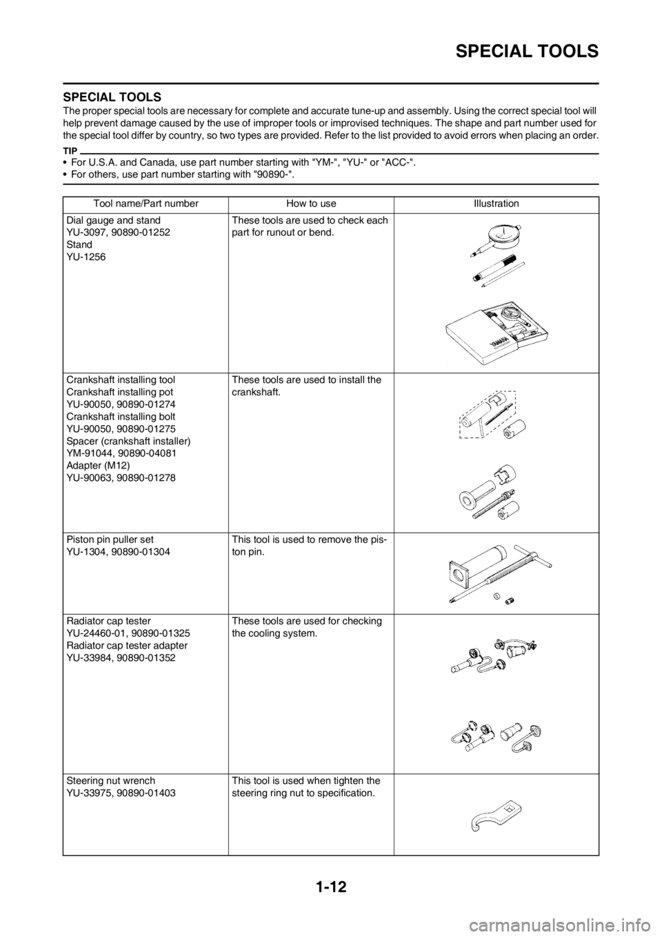
The proper special tools are necessary for complete and accurate tune-up and assembly. Using the correct special tool will
help prevent damage caused by the use of improper tools or improvised techniques. The shape and part number used for
the special tool differ by country, so two types are provided. Refer to the list provided to avoid errors when placing an order.
• For U.S.A. and Canada, use part number starting with "YM-", "YU-" or "ACC-".
• For others, use part number starting with "90890-".
Tool name/Part number How to use Illustration
Dial gauge and stand
YU-3097, 90890-01252
Stand
YU-1256These tools are used to check each
part for runout or bend.
Crankshaft installing tool
Crankshaft installing pot
YU-90050, 90890-01274
Crankshaft installing bolt
YU-90050, 90890-01275
Spacer (crankshaft installer)
YM-91044, 90890-04081
Adapter (M12)
YU-90063, 90890-01278These tools are used to install the
crankshaft.
Piston pin puller set
YU-1304, 90890-01304 This tool is used to remove the pis-
ton pin.
Radiator cap tester
YU-24460-01, 90890-01325
Radiator cap tester adapter
YU-33984, 90890-01352These tools are used for checking
the cooling system.
Steering nut wrench
YU-33975, 90890-01403 This tool is used when tighten the
steering ring nut to specification.
Page 23 of 228
1-13
SPECIAL TOOLS
Cap bolt wrench
YM-01500, 90890-01500This tool is used to loosen or tighten
the base valve.
Cap bolt ring wrench
YM-01501, 90890-01501This tool is used to loosen or tighten
the damper assembly.
Fork seal driver
YM-A0948, 90890-01502 This tool is used when install the fork
oil seal.
Spoke nipple wrench
YM-01521, 90890-01521 This tool is used to tighten the
spoke.
Pocket tester
YU-03112-C, 90890-03112 Use this tool to inspect the coil resis-
tance, output voltage and amper-
age.
Timing light
YM-33277-A, 90890-03141 This tool is necessary for checking
ignition timing.
Pressure gauge
YU-03153, 90890-03153 This tool is used to measure the fuel
pressure. Tool name/Part number How to use Illustration
Page 24 of 228

1-14
SPECIAL TOOLS
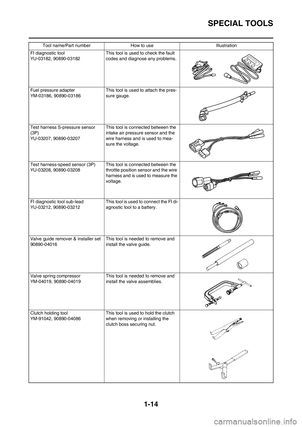
FI diagnostic tool
YU-03182, 90890-03182This tool is used to check the fault
codes and diagnose any problems.
Fuel pressure adapter
YM-03186, 90890-03186This tool is used to attach the pres-
sure gauge.
Test harness S-pressure sensor
(3P)
YU-03207, 90890-03207This tool is connected between the
intake air pressure sensor and the
wire harness and is used to mea-
sure the voltage.
Test harness-speed sensor (3P)
YU-03208, 90890-03208This tool is connected between the
throttle position sensor and the wire
harness and is used to measure the
voltage.
FI diagnostic tool sub-lead
YU-03212, 90890-03212This tool is used to connect the FI di-
agnostic tool to a battery.
Valve guide remover & installer set
90890-04016This tool is needed to remove and
install the valve guide.
Valve spring compressor
YM-04019, 90890-04019This tool is needed to remove and
install the valve assemblies.
Clutch holding tool
YM-91042, 90890-04086This tool is used to hold the clutch
when removing or installing the
clutch boss securing nut. Tool name/Part number How to use Illustration