Page 153 of 162

10-2
10
Type:SAE 5W-30, 10W-30, 10W-40, 15W-40, 20W-40 or 20W-
50
Recommended engine oil grade: API service SG type or higher, JASO standard MA
Engine oil quantity: Without oil filter element replacement:
1.75 L (1.85 US qt, 1.54 Imp.qt)
With oil filter element replacement: 1.85 L (1.96 US qt, 1.63 Imp.qt)Cooling system:Coolant reservoir capacity (up to the maximum level mark):
0.25 L (0.26 US qt, 0.22 Imp.qt)
Radiator capacity (including all routes): 1.61 L (1.70 US qt, 1.42 Imp.qt)
Air filter:Air filter element:Wet elementFuel:Recommended fuel:YFM700RD Unleaded gasoline only
YFM700RSED Unleaded gasoline only
YFM7RD Regular unleaded gasoline only
YFM7RSED Regular unleaded gasoline only
Fuel tank capacity: 11.0 L (2.91 US gal, 2.42 Imp.gal)
Fuel reserve amount:
2.9 L (0.77 US gal, 0.64 Imp.gal)Fuel injection:Throttle body:ID mark:1S3H 10Spark plug (s):Manufacturer/model:
NGK/CR8E
Spark plug gap: 0.7–0.8 mm (0.028–0.031 in)Clutch:Clutch type:
Wet, multiple-discTransmission:Primary reduction system:Spur gear
Primary reduction ratio:
77/34 (2.265)
0 10 30 50 70 90 110 130 �F
–20 –10 0 10 20 30 40 50 �CSAE 5W-30
SAE 10W-30
SAE 10W-40
SAE 15W-40
SAE 20W-40SAE 20W-50
U1PE60E0.book Page 2 Friday, March 2, 2012 1:22 PM
Page 154 of 162

Transmission type:
Constant mesh 5-speed.forward, 1-speed.reverse
Operation: Left foot operation
Gear ratio: 1st")
10-3
10
Secondary reduction system:Chain drive
Secondary reduction ratio: 38/14 (2.714)
Transmission type:
Constant mesh 5-speed.forward, 1-speed.reverse
Operation: Left foot operation
Gear ratio: 1st: 38/13 (2.923)
2nd: 28/14 (2.000)
3rd:
25/17 (1.471)
4th: 25/22 (1.136)
5th: 22/24 (0.917)
Reverse gear:
24/13 × 29/12 (4.462)Chassis:Frame type:
Aluminum die-cast and steel tube frame
Caster angle:
5.0 °
Trail: 21.0 mm (0.83 in)Front tire:Type:
Tubeless Size:
AT21 x 7-10
Manufacturer/model: MAXXIS/M971Y Bias
Speed rating:
130 km/h (80.8 mph)
Rear tire:Type:Tubeless
Size:
AT20 x 10-9
Manufacturer/model: MAXXIS/M976Y Bias
Speed rating: 130 km/h (80.8 mph)Loading:Maximum loading limit:100.0 kg (220 lb)
(Total weight of rider, cargo, accessories, and tongue)Tire air pressure (measured on cold tires):Recommended:Front: 27.5 kPa (0.275 kgf/cm², 4.0 psi)
Rear: 27.5 kPa (0.275 kgf/cm², 4.0 psi)
Minimum:
Front: 24.5 kPa (0.245 kgf/cm², 3.6 psi)
Rear:
24.5 kPa (0.245 kgf/cm², 3.6 psi)
U1PE60E0.book Page 3 Friday, March 2, 2012 1:22 PM
Page 155 of 162
10-4
10
Front wheel:Wheel type:Panel wheel
Rim size:
10 x 5.5ATRear wheel:Wheel type:Panel wheel
Rim size:
9 x 8.0ATFront brake:Type:Disc brake
Operation:
Right hand operation
Specified brake fluid: DOT 4Rear brake:Type:
Disc brake
Operation: Right foot operation
Specified brake fluid: DOT 4Front suspension:Type:Double wishbone Spring/shock absorber type:
YFM700RD Coil spring/oil damper
YFM700RSED Coil spring/gas-oil damper
YFM7RD Coil spring/oil damper
YFM7RSED Coil spring/gas-oil damper
Wheel travel: 230 mm (9.1 in)
Rear suspension:Type:Swingarm (link suspension)
Spring/shock absorber type: Coil spring/gas-oil damper
Wheel travel:
256 mm (10.1 in)Electrical system:Ignition system:TCI
Charging system:
AC magnetoBattery:Model:GT9B-4
Voltage, capacity:
12 V, 8.0 AhHeadlight:Bulb type:Krypton bulbBulb voltage, wattage × quantity:Headlight:
12 V, 30.0/30.0 W × 2
U1PE60E0.book Page 4 Friday, March 2, 2012 1:22 PM
Page 156 of 162

10-5
10
Tail/brake light:LED
Neutral indicator light: LED
Fuel level warning light:
LED
Reverse indicator light: LED
Coolant temperature warning light: LED
Engine trouble warning light:
LEDFuses:Main fuse:30.0 A
Fuel injection system fuse:
10.0 A
Headlight fuse: 10.0 A
Signaling system fuse: 10.0 A
Ignition fuse:
10.0 A
Radiator fan fuse: 20.0 A
EBU30401For Europe only
The figures quoted are emission levels and are not
necessarily safe working levels. Whilst there is a
correlation between the emission and exposure
levels, this cannot be used reliably to determine
whether or not further precautions are required.
Factors that influence the actual level of exposure
of work-force include the characteristics of the
work room, the other sources of noise, etc. i.e. the
number of machines and other adjacent process-
es, and the length of time for which an operator is
exposed to the noise. Also the permissible expo-
sure level can vary from country. This information,
however, will enable the user of the machine to
make a better evaluation of the hazard and risk.
U1PE60E0.book Page 5 Friday, March 2, 2012 1:22 PM
Page 157 of 162
11-1
11
EBU26000
CONSUMER INFORMATION
EBU28201Identification numbers Record the vehicle identification number and mod-
el label information in the spaces provided below
for assistance when ordering spare parts from a
Yamaha dealer or for reference in case the ATV is stolen.
VEHICLE IDENTIFICATION NUMBER:
MODEL LABEL INFORMATION:EBU26030Vehicle identification number
The vehicle identification number is stamped into
the frame.
TIPThe vehicle identification number is used to identify
your ATV.EBU26050Model label
The model label is affixed at the location in the il-
lustration. Record the information on this label in
the space provided. This information will be need-
ed when ordering spare parts from a Yamaha deal-
er.1. Vehicle identification number
1
U1PE60E0.book Page 1 Friday, March 2, 2012 1:22 PM
Page 158 of 162
11-2
11
1. Model label
1
U1PE60E0.book Page 2 Friday, March 2, 2012 1:22 PM
Page 159 of 162

INDEX
AAccessories and loading ................................................ 6-7
Air filter element, cleaning ............................................ 8-21BBattery .......................................................................... 8-46
Brake and clutch levers, checking and lubricating ....... 8-42
Brake fluid, changing ................................................... 8-34
Brake fluid level, checking ........................................... 8-31
Brake lever free play, checking the front ...................... 8-34
Brake lever (YFM7RD/YFM700RD) ............................... 4-6
Brake lever (YFM7RSED/YFM700RSED) ..................... 4-7
Brake light switches ..................................................... 8-36
Brake pads, checking the front and rear ...................... 8-30
Brake pedal .................................................................... 4-7
Brake pedal, checking and lubricating ......................... 8-42
Brake pedal height, checking ....................................... 8-34
Brakes .......................................................................... 8-29
Brakes, front and rear .................................................... 5-4CCables, checking and lubricating ................................. 8-41
Chassis fasteners .......................................................... 5-7
Cleaning ......................................................................... 9-1
Clutch lever .................................................................... 4-6
Clutch lever free play, adjusting ................................... 8-37
Coolant .................................................................. 5-4, 8-17
Coolant temperature warning light ................................. 4-2DDrive chain ..................................................................... 5-5Drive chain, lubricating ................................................ 8-40
Drive chain slack .......................................................... 8-38
EEngine break-in .............................................................. 6-5
Engine idling speed ..................................................... 8-27
Engine oil ....................................................................... 5-4
Engine oil and oil filter element .................................... 8-13
Engine, start ................................................................... 6-1
Engine stop switch ......................................................... 4-4
Engine trouble warning light .......................................... 4-3FFuel ....................................................................... 4-10, 5-4
Fuel level warning light .................................................. 4-3
Fuel tank cap ............................................................... 4-10
Fuses, replacing .......................................................... 8-48HHandlebar switches ....................................................... 4-4
Headlight beam, adjusting ........................................... 8-52
Headlight bulb, replacing ............................................. 8-50IIdentification numbers .................................................. 11-1
Indicator lights and warning lights .................................. 4-2
Instruments, lights and switches .................................... 5-7LLabel locations ............................................................... 1-1
Light switch .................................................................... 4-4MMain switch .................................................................... 4-1
U1PE60E0.book Page 1 Friday, March 2, 2012 1:22 PM
Page 160 of 162

Maintenance and lubrication chart ................................. 8-5
Maintenance chart, emission control system ................. 8-3
Model label ................................................................... 11-1NNeutral indicator light ..................................................... 4-2OOwner’s manual and tool kit ........................................... 8-2PPanel, removing and installing ..................................... 8-10
Parking ........................................................................... 6-6
Parking brake free play, adjusting ................................ 8-35
Parking brake lever ........................................................ 4-8
Parking on a slope ......................................................... 6-6
Part locations ................................................................. 3-1RReverse indicator light .................................................... 4-2
Reverse knob ................................................................. 4-9
Reverse knob and driving in reverse .............................. 6-4
Reverse lock release cable, adjusting .......................... 8-29
Riding your ATV ............................................................. 7-1SSafety information .......................................................... 2-1
Seat .............................................................................. 4-12
Self-diagnosis device ..................................................... 4-3
Shifting ........................................................................... 6-2
Shift pedal ...................................................................... 4-9
Shift pedal, checking .................................................... 8-42
Shock absorber assemblies, adjusting the front (YFM7RD/YFM700RD) .............................................. 4-13
Shock absorber assemblies, adjusting the front
(YFM7RSED/YFM700RSED) .................................... 4-15 Shock absorber assembly, adjusting the rear
(YFM7RD/YFM700RD) .............................................. 4-19
Shock absorber assembly, adjusting the rear (YFM7RSED/YFM700RSED) .................................... 4-21
Spark arrester, cleaning ............................................... 8-25
Spark plug, checking .................................................... 8-10
Specifications ............................................................... 10-1
Speed limiter .................................................................. 4-5
Start switch ..................................................................... 4-4
Steering shaft, lubricating ............................................. 8-45
Storage ........................................................................... 9-2
Suspension, lubricating the upper and lower arm pivots ......................................................... 8-44
Suspension relay arm and connecting arm pivoting
points, lubricating the rear ......................................... 8-43
Swingarm pivots, lubricating ........................................ 8-43
TTail/brake light .............................................................. 8-52
Throttle lever ........................................................... 4-4, 5-5
Throttle lever free play, adjusting ................................. 8-28
Tires ............................................................................... 5-5
Troubleshooting ........................................................... 8-54
Troubleshooting charts ................................................. 8-55VValve clearance ............................................................ 8-29
Vehicle identification number ....................................... 11-1WWheel hub bearings, checking ..................................... 8-42
Wheel, installing ........................................................... 8-53
Wheel, removing .......................................................... 8-52
U1PE60E0.book Page 2 Friday, March 2, 2012 1:22 PM
 1
1 2
2 3
3 4
4 5
5 6
6 7
7 8
8 9
9 10
10 11
11 12
12 13
13 14
14 15
15 16
16 17
17 18
18 19
19 20
20 21
21 22
22 23
23 24
24 25
25 26
26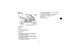 27
27 28
28 29
29 30
30 31
31 32
32 33
33 34
34 35
35 36
36 37
37 38
38 39
39 40
40 41
41 42
42 43
43 44
44 45
45 46
46 47
47 48
48 49
49 50
50 51
51 52
52 53
53 54
54 55
55 56
56 57
57 58
58 59
59 60
60 61
61 62
62 63
63 64
64 65
65 66
66 67
67 68
68 69
69 70
70 71
71 72
72 73
73 74
74 75
75 76
76 77
77 78
78 79
79 80
80 81
81 82
82 83
83 84
84 85
85 86
86 87
87 88
88 89
89 90
90 91
91 92
92 93
93 94
94 95
95 96
96 97
97 98
98 99
99 100
100 101
101 102
102 103
103 104
104 105
105 106
106 107
107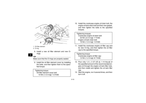 108
108 109
109 110
110 111
111 112
112 113
113 114
114 115
115 116
116 117
117 118
118 119
119 120
120 121
121 122
122 123
123 124
124 125
125 126
126 127
127 128
128 129
129 130
130 131
131 132
132 133
133 134
134 135
135 136
136 137
137 138
138 139
139 140
140 141
141 142
142 143
143 144
144 145
145 146
146 147
147 148
148 149
149 150
150 151
151 152
152 153
153 154
154 155
155 156
156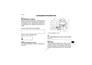 157
157 158
158 159
159 160
160 161
161

