Page 57 of 90

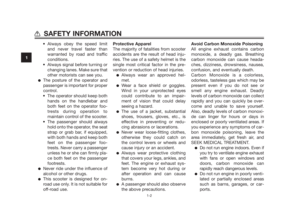
3. Remove the engine oil filler cap
and the engine oil drain bolt to
drain the oil from the crankcase.
1. Engine oil drain bolt
4. Check the washer for damage
and replace it if necessary.
1. Engine oil drain bolt
2. Washer
5. Install the washer and the engine
oil drain bolt, and then tighten the
drain bolt to the specified torque.
TIP
Make sure that the washer is properly
seated.
6. Refill with the specified amount
of the recommended engine oil,
and then install and tighten the oil
filler cap.
ECA11670
�Do not use oils with a diesel
specification of “CD” or oils of
a higher quality than specified.
In addition, do not use oils
labeled “ENERGY CONSER-
VING II” or higher.
�Be sure no foreign material
enters the crankcase.
7. Start the engine, and then let it
idle for several minutes while
checking it for oil leakage. If oil is
leaking, immediately turn the
engine off and check for the cau-
se.
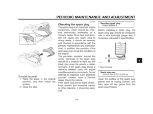
8. Reset the oil change indicator.
To reset the oil change indicator
1. Turn the key to “ON”.
2. Hold the “OIL CHANGE” button
pushed for 15 to 20 seconds.
1. “OIL CHANGE” button
NOTICE
Recommended engine oil:
See page 8-1
Oil change quantity:
1.30 L (1.37 US qt, 1.14 Imp.qt)
Tightening torque:
Engine oil drain bolt:
12ZAUM0129
11
ZAUM0686
PERIODIC MAINTENANCE AND ADJUSTMENT
6-11
6
Page 58 of 90

1. “OIL CHANGE” button
3. Release the “OIL CHANGE” but-
ton, and the oil change indicator
will go off.
TIP
If the engine oil is changed before the
oil change indicator comes on (i.e.
before the periodic oil change interval
has been reached), the indicator must
be reset after the oil change for the
next periodic oil change to be indica-
ted at the correct time. To reset the oil
change indicator before the periodic
oil change interval has been reached,
follow the above procedure, but note
that the indicator will come on for 1.4
seconds after releasing the “OILCHANGE” button, otherwise repeat
the procedure.
EAU20065
Final transmission oil
The final transmission case must be
checked for oil leakage before each
ride. If any leakage is found, have a
Yamaha dealer check and repair the
scooter. In addition, the final trans-
mission oil must be changed as
follows at the intervals specified in the
periodic maintenance and lubrication
chart.
1. Start the engine, warm up the
final transmission oil by riding the
scooter for several minutes, and
then stop the engine.
2. Place the scooter on the centers-
tand.
3. Place an oil pan under the final
transmission case to collect the
used oil.
4. Remove the final transmission oil
filler cap and its O-ring from the
final transmission case.
5. Remove the final transmission oil
drain bolt and its gasket to drain
the oil from the final transmission
case.
PERIODIC MAINTENANCE AND ADJUSTMENT
6-12
6
Page 59 of 90

1. Final transmission oil filler cap
2. O-ring
6. Install the final transmission oil
drain bolt and its new gasket,
and then tighten the bolt to the
specified torque.
1. Final transmission oil drain bolt
7. Refill with the specified amount
of the recommended final trans-
mission oil. WARNING! Make
sure that no foreign material
enters the final transmission
case. Make sure that no oil
gets on the tire or wheel.
[EWA11311]
8. Install the final transmission oil
filler cap and its new O-ring, and
then tighten the oil filler cap.
9. Check the final transmission case
for oil leakage. If oil is leaking,
check for the cause.
EAU20070
Coolant
The coolant level should be checked
before each ride. In addition, the coo-
lant must be changed at the intervals
specified in the periodic maintenance
and lubrication chart.
EAUS1670
To check the coolant level
1. Place the vehicle on a level surfa-
ce and hold it in an upright posi-
tion.
TIP
�The coolant level must be chec-
ked on a cold engine since the
level varies with engine tempera-
ture.
�Make sure that the vehicle is
positioned straight up when
checking the coolant level. A
slight tilt to the side can result in
a false reading.
2. Check the coolant level through
the check window.
Recommended final transmission
oil:
See page 8-1
Oil quantity:
0.25 L (0.26 US qt, 0.22 Imp.qt)
Tightening torque:
Final transmission oil drain bolt:
PERIODIC MAINTENANCE AND ADJUSTMENT
6-13
6
Page 60 of 90

TIP
The coolant should be between the
minimum and maximum level marks.
1. Maximum level mark
2. Minimum level mark
3. Coolant level check window
3. If the coolant is at or below the
minimum level mark, lift up the
right floorboard mat as shown.
1. Floorboard mat
4. Open the reservoir cap, and then
add coolant to the maximum
level mark. WARNING! Remove
only the coolant reservoir cap.
Never attempt to remove the
radiator cap when the engine is
hot.
[EWA15161]
NOTICE: If coolant is not avai-
lable, use distilled water or soft
tap water instead. Do not use
hard water or salt water since it
is harmful to the engine. If
water has been used instead of
coolant, replace it with coolant
as soon as possible, otherwise
the cooling system will not be
protected against frost andcorrosion. If water has been
added to the coolant, have a
Yamaha dealer check the anti-
freeze content of the coolant
as soon as possible, otherwise
the effectiveness of the coolant
will be reduced.
[ECA10472]
1. Coolant reservoir cap
5. Close the reservoir cap
6. Place the floorboard mat in the
original position and push it
downward to secure it.
Coolant reservoir capacity:
0.25 L (0.26 US qt, 0.22 Imp.qt)
FULL
LOW
PERIODIC MAINTENANCE AND ADJUSTMENT
6-14
6
Page 61 of 90

EAU33031
Changing the coolant
The coolant must be changed at the
intervals specified in the periodic
maintenance and lubrication chart.
Have a Yamaha dealer change the
coolant. WARNING! Never attempt
to remove the radiator cap when
the engine is hot.
[EWA10381]EAUS1334
Air filter and V-belt case air
filter elements
The air filter element should be repla-
ced and the V-belt case air filter ele-
ment should be cleaned at the inter-
vals specified in the periodic
maintenance and lubrication chart.
Service the air filter elements more
frequently if you are riding in unu-
sually wet or dusty areas.
Replacing the air filter element
1. Place the scooter on the centers-
tand.
2. Remove the air filter case cover
by removing the screws.
1. Air filter case cover
2. Screw
3. Air filter element
3. Pull the air filter element out.
4. Insert a new air filter element into
the air filter case.
5. Install the air filter case cover by
installing the screws.
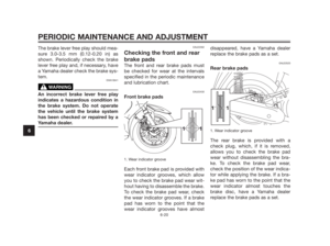
Cleaning the V-belt case air filter
element
1. Remove the V-belt case air filter
cover by removing the screws.
1. V-belt case air filter element cover
2. Screw
2. Remove the air filter element, and
then blow out the dirt with com-
pressed air as shown.
21
ZAUM0448
1
2 2
ZAUM06623
PERIODIC MAINTENANCE AND ADJUSTMENT
6-15
6
Page 62 of 90

1. V-belt case air filter cover
2. V-belt case air filter element
3. Check the air filter element for
damage and replace it if neces-
sary.
4. Install the air filter element with
the colored side facing outward.
NOTICE: Make sure that each
filter element is properly sea-
ted in its case. The engine
should never be operated wit-
hout the filter elements insta-
lled, otherwise the piston(s)
and/or cylinder(s) may become
excessively worn.
[ECA10531]
5. Install the V-belt case air filter
cover by installing the screws.
EAU48431
Adjusting the throttle cable
free play
1. Throttle cable free play
The throttle cable free play should
measure 3.0–5.0 mm (0.12–0.20 in) at
the inner edge of the throttle grip.
Periodically check the throttle cable
free play and, if necessary, adjust it as
follows.
TIP
The engine idling speed must be
correctly adjusted before checking
and adjusting the throttle cable free
play.
1. Slide the rubber cover back.
2. Loosen the locknut.3. To increase the throttle cable free
play, turn the adjusting nut in
direction (a). To decrease the
throttle cable free play, turn the
adjusting nut in direction (b).
1. Rubber cover
2. Locknut
3. Adjusting nut
4. Tighten the locknut and then sli-
de the rubber cover to its original
position.
21
ZAUM0449
PERIODIC MAINTENANCE AND ADJUSTMENT
6-16
6
Page 63 of 90

EAU21401
Valve clearance
The valve clearance changes with
use, resulting in improper air-fuel mix-
ture and/or engine noise. To prevent
this from occurring, the valve clearan-
ce must be adjusted by a Yamaha
dealer at the intervals specified in the
periodic maintenance and lubrication
chart.
EAU21873
Tires
To maximize the performance, durabi-
lity, and safe operation of your vehi-
cle, note the following points regar-
ding the specified tires.
Tire air pressure
The tire air pressure should be chec-
ked and, if necessary, adjusted befo-
re each ride.
EWA10501
Operation of this vehicle with
improper tire pressure may cause
severe injury or death from loss of
control.
�The tire air pressure must be
checked and adjusted on coldtires (i.e., when the temperatu-
re of the tires equals the
ambient temperature).
�The tire air pressure must be
adjusted in accordance with
the riding speed and with the
total weight of rider, passenger,
cargo, and accessories appro-
ved for this model.
Tire air pressure (measured on
cold tires):
0–90 kg (0–198 lb):
Front:
190 kPa (1.90 kgf/cm
2,
28 psi, 1.90 bar)
Rear:
220 kPa (2.20 kgf/cm
2,
32 psi, 2.20 bar)
90 kg - maximum load:
Front:
210 kPa (2.10 kgf/cm
2,
30 psi, 2.10 bar)
Rear:
250 kPa (2.50 kgf/cm
2,
36 psi, 2.50 bar)
Maximum load*:
YP250R 175 kg (386 lb)
YP250RA 171 kg (377 lb))
YP250R Sport 173.5 kg (383 lb)
* Total weight of rider, passenger,
cargo and accessories WARNING
ZAUM0053
PERIODIC MAINTENANCE AND ADJUSTMENT
6-17
6
Page 64 of 90

EWA10511
Never overload your vehicle. Ope-
ration of an overloaded vehicle
could cause an accident.
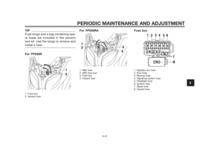
Tire inspection
1. Tire tread depth
2. Tire sidewall
The tires must be checked before
each ride. If the center tread depth
reaches the specified limit, if the tire
has a nail or glass fragments in it, or if
the sidewall is cracked, have a Yama-
ha dealer replace the tire immediately.
TIP
The tire tread depth limits may differ
from country to country. Always
comply with the local regulations.
Tire information
This model is equipped with tubeless
tires.
After extensive tests, only the tires lis-
ted below have been approved for
this model by Yamaha Motor España
S. A.
EWA10470
�Have a Yamaha dealer replace
excessively worn tires. Besides
being illegal, operating the
vehicle with excessively worn
tires decreases riding stability
and can lead to loss of control.
�The replacement of all wheel
and brake related parts, inclu-
ding the tires, should be left to
a Yamaha dealer, who has the
WARNING
Front tire:
Size:
120/70-15 M/C 56P(PIRELLI-
METZELER)-56S(MICHELIN)
Manufacturer/model:
PIRELLI / GTS23
MICHELIN / GOLD STANDARD
MICHELIN / CITYGRIP
METZELER / FEELFREE
Rear tire:
Size:
140/70-14 M/C 68P(PIRELLI-
METZELER)-68S(MICHELIN)
Manufacturer/model:
PIRELLI / GTS24
MICHELIN / GOLD STANDARD
MICHELIN / CITYGRIP
METZELER / FEELFREEMinimum tire tread depth (front
and rear):
1.6 mm (0.06 in)
1
2
ZAUM0054
WARNING
PERIODIC MAINTENANCE AND ADJUSTMENT
6-18
6
After extensive tests, only the tires lis-
ted below have been approved for this
model by Yamaha Motor Co., Ltd.