Page 57 of 82

PERIODIC MAINTENANCE AND ADJUSTMENT
6-26
6
EAU45511
Checking the steering Worn or loose steering bearings may
cause danger. Therefore, the operation
of the steering must be checked as fol-
lows at the intervals specified in the pe-
riodic maintenance and lubrication
chart.
1. Place the vehicle on the center-
stand. WARNING! To avoid inju-
ry, securely support the vehicle
so there is no danger of it falling
over.
[EWA10751]
2. Hold the lower ends of the front
fork legs and try to move them for-
ward and backward. If any free
play can be felt, have a Yamaha
dealer check or repair the steering.
EAU23291
Checking the wheel bearings The front and rear wheel bearings must
be checked at the intervals specified in
the periodic maintenance and lubrica-
tion chart. If there is play in the wheel
hub or if the wheel does not turn
smoothly, have a Yamaha dealer check
the wheel bearings.
EAU47812
Battery The battery is located under the seat.
(See page 3-8.)
This model is equipped with a VRLA
(Valve Regulated Lead Acid) battery.
There is no need to check the electro-
lyte or to add distilled water. However,
the battery lead connections need to be
checked and, if necessary, tightened.
WARNING
EWA10760
●
Electrolyte is poisonous and
dangerous since it contains sul-
furic acid, which causes severe
burns. Avoid any contact with
skin, eyes or clothing and al-
ways shield your eyes when
working near batteries. In case
of contact, administer the fol-
lowing FIRST AID.
EXTERNAL: Flush with plenty
of water.
INTERNAL: Drink large quan-
tities of water or milk and im-
mediately call a physician.
EYES: Flush with water for 15
minutes and seek prompt
medical attention.
U40BE2E0.book Page 26 Wednesday, October 10, 2012 8:01 AM
Page 58 of 82

PERIODIC MAINTENANCE AND ADJUSTMENT
6-27
6
●
Batteries produce explosive hy-
drogen gas. Therefore, keep
sparks, flames, cigarettes, etc.,
away from the battery and pro-
vide sufficient ventilation when
charging it in an enclosed
space.
●
KEEP THIS AND ALL BATTER-
IES OUT OF THE REACH OF
CHILDREN.
NOTICE
ECA10620
Never attempt to remove the battery
cell seals, as this would permanent-
ly damage the battery.To charge the battery
Have a Yamaha dealer charge the bat-
tery as soon as possible if it seems to
have discharged. Keep in mind that the
battery tends to discharge more quickly
if the vehicle is equipped with optional
electrical accessories.
NOTICE
ECA16521
To charge a VRLA (Valve Regulated
Lead Acid) battery, a special (con-
stant-voltage) battery charger is re-
quired. Using a conventional battery
charger will damage the battery.To store the battery
1. If the vehicle will not be used for
more than one month, remove the
battery, fully charge it, and then
place it in a cool, dry place.
NOTICE: When removing the
battery, be sure the key is
turned to “ ”, then disconnect
the negative lead before discon-
necting the positive lead.
[ECA17710]
2. If the battery will be stored for more
than two months, check it at least
once a month and fully charge it if
necessary.
3. Fully charge the battery before in-
stallation. NOTICE: When install-
ing the battery, be sure the key
is turned to “ ”, then connect
the positive lead before con-
necting the negative lead.
[ECA17720]
4. After installation, make sure that
the battery leads are properly con-
nected to the battery terminals.NOTICE
ECA16530
Always keep the battery charged.
Storing a discharged battery can
cause permanent battery damage.
U40BE2E0.book Page 27 Wednesday, October 10, 2012 8:01 AM
Page 59 of 82

PERIODIC MAINTENANCE AND ADJUSTMENT
6-28
6
EAU47672
Replacing the fuse The fuse holder is located under the
battery box cover.
If the fuse is blown, replace it as fol-
lows.
1. Turn the key to “ ” and turn off all
electrical circuits.
2. Open the seat. (See page 3-8.)
3. Remove the battery box cover by
removing the screw.
4. Remove the blown fuse, and then
install a new fuse of the specified
amperage. WARNING! Do not
use a fuse of a higher amperage
rating than recommended toavoid causing extensive dam-
age to the electrical system and
possibly a fire.
[EWA15131]
5. Turn the key to “ ” and turn on
the electrical circuits to check if the
devices operate.
6. If the fuse immediately blows
again, have a Yamaha dealer
check the electrical system.
7. Install the battery box cover by in-
stalling the screw.
8. Close the seat.
EAU47761
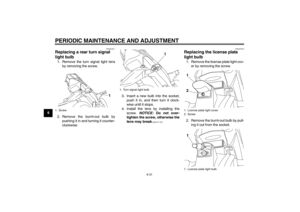
Replacing the headlight bulb If the headlight bulb burns out, replace
it as follows.NOTICE
ECA10650
Take care not to damage the follow-
ing parts:●
Headlight bulb
Do not touch the glass part of
the headlight bulb to keep it free
from oil, otherwise the transpar-
ency of the glass, the luminosity
of the bulb, and the bulb life will
be adversely affected. Thor-
oughly clean off any dirt and fin-
gerprints on the headlight bulb
using a cloth moistened with al-
cohol or thinner.
●
Headlight lens
Do not affix any type of tinted
film or stickers to the headlight
lens.
Do not use a headlight bulb of a
wattage higher than specified.
1. Battery box cover
2. Screw
1
2
1. Fuse
2. Spare fuse
Specified fuse:
10.0 A
12
U40BE2E0.book Page 28 Wednesday, October 10, 2012 8:01 AM
Page 60 of 82
PERIODIC MAINTENANCE AND ADJUSTMENT
6-29
61. Remove cowling A. (See page
6-7.)
2. Remove the headlight bulb cover.
3. Remove the headlight bulb holder
(together with the bulb) by turning
it counterclockwise.4. Remove the burnt-out bulb by
pushing it in and turning it counter-
clockwise.
5. Place a new bulb into the holder,
push it in, and then turn it clock-
wise until it stops.
6. Install the bulb holder (together
with the bulb) by turning it clock-
wise.
7. Install the headlight bulb cover.
8. Install the cowling.
9. Have a Yamaha dealer adjust the
headlight beam if necessary.
EAU47660
Replacing the tail/brake light
bulb 1. Remove the tail/brake light outer
lens by removing the screws.
2. Remove the inner lens by pulling it
out.
1. Do not touch the glass part of the bulb.
1. Headlight bulb cover
1
1
1. Headlight bulb holder
2. Headlight bulb
1
2
1. Outer lens
2. Screw
1. Inner lens
21
1
U40BE2E0.book Page 29 Wednesday, October 10, 2012 8:01 AM
Page 61 of 82

PERIODIC MAINTENANCE AND ADJUSTMENT
6-30
6 3. Remove the burnt-out bulb by
pushing it in and turning it counter-
clockwise.
4. Insert a new bulb into the socket,
push it in, and then turn it clock-
wise until it stops.
5. Place the inner lens in the original
position, and then install the outer
lens by installing the screws.
NOTICE: Do not overtighten the
screws, otherwise the lens may
break.
[ECA10681]EAU47741
Replacing a front turn signal
light bulb 1. Remove cowling A. (See page
6-7.)
2. Remove the turn signal light bulb
socket (together with the bulb) by
turning it counterclockwise.
3. Remove the burnt-out bulb by
pushing it in and turning it counter-
clockwise.4. Insert a new bulb into the socket,
push it in, and then turn it clock-
wise until it stops.
5. Install the socket (together with the
bulb) by turning it clockwise.
6. Install the cowling.
1. Tail/brake light bulb
1
1. Turn signal light bulb socket
1
1. Turn signal light bulb
1
U40BE2E0.book Page 30 Wednesday, October 10, 2012 8:01 AM
Page 62 of 82
PERIODIC MAINTENANCE AND ADJUSTMENT
6-31
6
EAUS1611
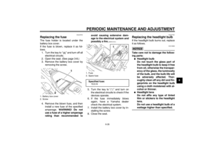
Replacing a rear turn signal
light bulb 1. Remove the turn signal light lens
by removing the screw.
2. Remove the burnt-out bulb by
pushing it in and turning it counter-
clockwise.3. Insert a new bulb into the socket,
push it in, and then turn it clock-
wise until it stops.
4. Install the lens by installing the
screw. NOTICE: Do not over-
tighten the screw, otherwise the
lens may break.
[ECA11191]EAU47910
Replacing the license plate
light bulb 1. Remove the license plate light cov-
er by removing the screw.
2. Remove the burnt-out bulb by pull-
ing it out from the socket.
1. Screw
1
1. Turn signal light bulb
1
1. License plate light cover
2. Screw
1. License plate light bulb1
21
U40BE2E0.book Page 31 Wednesday, October 10, 2012 8:01 AM
Page 63 of 82
PERIODIC MAINTENANCE AND ADJUSTMENT
6-32
6 3. Insert a new bulb into the socket.
4. Install the license plate light cover
by installing the screw.
EAUW0343
Replacing an auxiliary light
bulb This model is equipped with two auxil-
iary lights. If an auxiliary light bulb burns
out, replace it as follows.
1. Remove cowling A. (See page
6-7.)
2. Remove the auxiliary light bulb
socket (together with the bulb) by
pulling it out.
3. Remove the burnt-out bulb by pull-
ing it out.4. Insert a new bulb into the socket.
5. Install the auxiliary light bulb sock-
et (together with the bulb) by push-
ing it in.
6. Install the cowling.1. Auxiliary light bulb socket
1
1. Auxiliary light bulb
1
U40BE2E0.book Page 32 Wednesday, October 10, 2012 8:01 AM
Page 64 of 82
PERIODIC MAINTENANCE AND ADJUSTMENT
6-33
6
EAU24360
Front wheel
EAU55220
To remove the front wheel
WARNING
EWA10821
To avoid injury, securely support the
vehicle so there is no danger of it
falling over.1. Place the motorcycle on the cen-
terstand.
2. Remove the rubber cap, and then
loosen the wheel axle nut.
3. Disconnect the speedometer ca-
ble from the front wheel.4. Remove the wheel axle nut and
the washer.
5. Pull the wheel axle out, and then
remove the wheel. NOTICE: Do
not apply the brake after the
wheel has been removed to-gether with the brake disc, oth-
erwise the brake pads will be
forced shut.
[ECA11071]
EAU55200
To install the front wheel
1. Install the speedometer gear unit
into the wheel hub so that the pro-
jection on the wheel hub fits in ei-
ther slot of the speedometer gear
unit.
1. Rubber cap
2. Wheel axle nut
12
1. Speedometer cable
1. Wheel axle nut
2. Washer
1
12
1. Wheel axle
1
U40BE2E0.book Page 33 Wednesday, October 10, 2012 8:01 AM


2. Remove the headlight bulb cover.
3. Remove the headlight bulb holder
(together with the bulb) by turning
it counterclo")


