Page 105 of 116

Trouble recovery
99
EJU34561
Troubleshooting
If you have any trouble with your watercraft, use the troubleshooting chart to check for the pos-
sible cause.
If you cannot find the cause, consult a Yamaha dealer.
EJU42351Troubleshooting chart
Confirm the possible cause and remedy, and then refer to the applicable page.
TROUBLE POSSIBLE CAUSE REMEDYPAGE
Engine does not
start (Starter motor
does not turn over) Yamaha Se-
curity System
Lock mode selected Select unlock mode
27
Engine shut-
off switch Clip not in place Install clip
28
Fuse Burned out Replace fuse and
check wiring 103
Battery Run down Recharge89
Poor terminal con-
nections Tighten as required
89
Terminal corroded Clean or replace 89
Starter motor Faulty Have serviced by
Yamaha dealer —
Engine does not
start (Starter motor
turns over) Throttle lever Squeezed
Release28
Fuel Fuel tank empty Refill as soon as pos-
sible 58
Stale or contaminat-
ed Have serviced by
Yamaha dealer
—
Fuel tank Water or dirt present Have serviced by Yamaha dealer—
Spark plug Fouled or defective Have serviced by Yamaha dealer—
Spark plug
cap Not connected or
loose Have serviced by
Yamaha dealer
—
Connected to wrong
cylinder Have serviced by
Yamaha dealer
—
Fuel injec-
tion system Fuel pump faulty Have serviced by
Yamaha dealer —
Throttle lever Faulty Have serviced by
Yamaha dealer —
UF2S71E0.book Page 99 Tuesday, August 21, 2012 2:33 PM
Page 106 of 116

Trouble recovery
100
Engine runs irregu-
larly or stallsFuel Fuel tank empty Refill as soon as pos-
sible58
Stale or contaminat-
ed Have serviced by
Yamaha dealer
—
Fuel tank Water or dirt present Have serviced by Yamaha dealer—
Spark plug Fouled or defective Have serviced by Yamaha dealer—
Incorrect heat range Have serviced by Yamaha dealer —
Gap incorrect Have serviced by Yamaha dealer —
Spark plug
cap Not connected or
loose Have serviced by
Yamaha dealer
—
Cracked, torn, or
damaged Have serviced by
Yamaha dealer
—
Electrical wir-
ing Loose connection Have serviced by
Yamaha dealer —
Fuel injec-
tion system Faulty or clogged in-
jectors Have serviced by
Yamaha dealer
—
Warning light or in-
dicator blinks or
comes on Fuel level
warning
Fuel tank empty Refill as soon as pos-
sible 58
Oil pressure
warning Oil pressure dropped Have serviced by
Yamaha dealer 44
Engine over-
heat warning Jet intake clogged Clean
102
Check engine
warning Faulty sensors Have serviced by
Yamaha dealer 45
TROUBLE POSSIBLE CAUSE REMEDY PAGE
UF2S71E0.book Page 100 Tuesday, August 21, 2012 2:33 PM
Page 107 of 116

Trouble recovery
101
Watercraft slow or
loses powerShift lever Not completely shift-
ed into forward posi-
tion Push lever forward
until it stops 32
Watercraft
operation
mode Low RPM Mode acti-
vated
Deactivate Low RPM
Mode 35
Cavitation Jet intake clogged Clean 102 Impeller damaged or
worn Have serviced by
Yamaha dealer
102
Engine over-
heat warning Engine speed reduc-
tion control activated Clean jet intake and
cool engine
44
Oil pressure
warning Engine speed reduc-
tion control activated Add oil
44
Spark plug Fouled or defective Have serviced by Yamaha dealer—
Incorrect heat range Have serviced by Yamaha dealer —
Gap incorrect Have serviced by Yamaha dealer —
Spark plug
cap Not connected or
loose Have serviced by
Yamaha dealer
—
Electrical wir-
ing Loose connection Have serviced by
Yamaha dealer —
Fuel Stale or contaminat- ed Have serviced by
Yamaha dealer
—
Air filter Clogged Have serviced by Yamaha dealer—
Oil buildup Have serviced by Yamaha dealer —
Throttle lever Faulty Have serviced by Yamaha dealer—
TROUBLE POSSIBLE CAUSE REMEDY PAGE
UF2S71E0.book Page 101 Tuesday, August 21, 2012 2:33 PM
Page 108 of 116

Trouble recovery
102
EJU34623
Emergency procedures EJU34634Cleaning the jet intake and impeller
WARNING
EWJ00782
Before attempting to remove weeds or de-
bris from the jet intake or impeller area,
shut the engine off and remove the clip
from the engine shut-off switch. Severe in-
jury or death could result from coming in
contact with the rotating parts of the jet
pump.
If weeds or debris gets caught in the jet intake
or impeller, cavitation can occur, causing jet
thrust to decrease even though engine speed
rises. If this condition is allowed to continue,
the engine will overheat and may seize.
NOTICE: If weeds or debris gets caught in
the jet intake, do not operate the watercraft
above trolling speed until they have been
removed.
[ECJ00653]
If there is any sign that the jet intake or impel-
ler is clogged with weeds or debris, return to
shore and check the intake and impeller. Al- ways stop the engine before beaching the wa-
tercraft.
(1) Place a suitable clean cloth or carpeting
underneath the watercraft to protect it
from abrasions and scratches. Turn the
watercraft on its side as shown. NOTICE:
Always turn the watercraft over onto
its port (left) side. When turning the
watercraft on its side, support the bow
so that the handlebars are not bent or
damaged.
[ECJ00661]
UF2S71E0.book Page 102 Tuesday, August 21, 2012 2:33 PM
Page 109 of 116
 Remove any weeds or debris fromaround the jet intake, drive shaft, impel-
ler, jet pump housing, and jet thrust noz-
zle.
If debris is difficult to remove, consult a
Yamaha de")
Trouble recovery
103
(2) Remove any weeds or debris fromaround the jet intake, drive shaft, impel-
ler, jet pump housing, and jet thrust noz-
zle.
If debris is difficult to remove, consult a
Yamaha dealer.
EJU34641Jumping the battery
If the watercraft battery has run down, the en-
gine can be started using a 12-volt booster
battery and jumper cables.
EJU34663Connecting the jumper cables
WARNING
EWJ01250
To avoid battery explosion and serious
damage to the electrical system:
●Do not reverse the polarity of the jumper
cables when connecting to the batteries.
●Do not connect the negative (–) jumper
cable to the negative (–) terminal of the
watercraft battery.
●Do not touch the positive (+) jumper ca-
ble to the negative (–) jumper cable.
(1) Connect the positive (+) jumper cable to the positive (+) battery terminals of both
batteries.
(2) Connect one end of the negative (–) jumper cable to the negative (–) battery
terminal of the booster battery. (3) Connect the other end of the negative (–)
jumper cable to an engine hanger.
(4) Start the engine, and then disconnect the jumper cables by reversing the steps
above. (See page 28 for information on
starting the engine.)
EJU36994Replacing the fuses
If a fuse is blown, replace it with the proper
fuse.
To replace a fuse:
(1) Remove the seats. (See page 49 for seatremoval and installation procedures.)
1Negative (–) jumper cable
2 Booster battery
3 Positive (+) jumper cable
4 Engine hanger
1 Good fuse
2 Blown fuse
1
4
3
2
2
1
UF2S71E0.book Page 103 Tuesday, August 21, 2012 2:33 PM
Page 110 of 116
Trouble recovery
104
(2) Remove the electrical box cover.
(3) Loosen the cap on the electrical box andremove it.
(4) Replace the blown fuse with the spare fuse of the correct amperage by using the
fuse puller on the reverse side of the cap.
WARNING! Do not use fuses of a dif- ferent amperage than recommended.
Substitution with a fuse that has an
improper rating can cause extensive electrical system damage and possi-
ble fire.
[EWJ00802]
(5) Securely install the cap by tightening it
until it stops.
(6) Securely install the electrical box cover in
its original position.
1Electrical box cover
1
1Electrical box
2 Spare fuse
3 Fuse
4 Cap
1 Fuse puller
Fuse amperage:
Battery fuse: 30 A
Main relay drive fuse: 10 A
Electronic throttle valve fuse:
10 A
Security system fuse: 3 A
Main fuse: 20 A
1
4 3
2
UF2S71E0.book Page 104 Tuesday, August 21, 2012 2:33 PM
Page 111 of 116
 Securely install the seats in their originalpositions.
If the fuse immediately blows again, the elec-
trical system may be defective. If this occurs,
have a Yamaha dealer serv")
Trouble recovery
105
(7) Securely install the seats in their originalpositions.
If the fuse immediately blows again, the elec-
trical system may be defective. If this occurs,
have a Yamaha dealer service the watercraft.
EJU41821Replacing the bilge pump fuse
If the fuse is blown, replace it with the proper
fuse.
To replace the fuse:
(1) Remove the seats and engine cover. (See page 49 for seat removal and instal-
lation procedures and page 94 for engine
cover removal and installation proce-
dures.)
(2) Remove the plastic ties that are securing the corrugated tube and bilge pump fuse
leads.
TIP:
Be careful not to drop the plastic ties into the
engine compartment.
(3) Pull out the bilge pump fuse holder fromthe rubber cover, and then remove the
fuse cover.
(4) Replace the blown fuse with the spare fuse of the correct amperage.
WARNING! Do not use fuses of a dif- ferent amperage than recommended.
Substitution with a fuse that has an
improper rating can cause extensive
electrical system damage and possi-
ble fire.
[EWJ00802]
TIP:
If the fuse is difficult to remove, use the fuse
puller on the reverse side of the electrical box
1 Good fuse
2 Blown fuse
2
1
1 Bilge pump fuse lead
2 Plastic tie
3 Corrugated tube
213
UF2S71E0.book Page 105 Tuesday, August 21, 2012 2:33 PM
Page 112 of 116

(5) Securely install the fuse cover, and thenfit the bilge pump fuse holder into the rub-
ber cover.
(6) Secure the bilge p")
Trouble recovery
106
cap. (See page 103 for information on the
fuse puller.)
(5) Securely install the fuse cover, and thenfit the bilge pump fuse holder into the rub-
ber cover.
(6) Secure the bilge pump fuse leads and corrugated tube with the plastic ties.
(7) Securely install the engine cover and seats in their original positions. If the fuse immediately blows again, the elec-
trical system may be defective. If this occurs,
have a Yamaha dealer service the watercraft.
EJU34715Towing the watercraft
WARNING
EWJ00811
●The operator of the towing boat must
keep speed to a minimum and avoid traf-
fic or obstacles which could be a hazard
to the operator on the watercraft.
●The towline should be long enough so
that the watercraft will not collide with
the towing boat when slowing down.
If the watercraft becomes inoperative in the
water, it can be towed to shore.
To tow the watercraft:
Use a towline that is three times the combined
length of the towing boat and the watercraft.
(1) Securely attach the towline to the bow
eye of the watercraft being towed.
(2) Sit astride the seat and hold on to the handlebars in order to balance the water-
craft. NOTICE: The bow must be kept
up out of the water during towing, oth-
erwise water could flood the engine
compartment or water could flow back
into the engine, causing severe en-
gine damage.
[ECJ01330]
1 Bilge pump fuse holder
2 Fuse cover
3 Spare fuse
4 Fuse
Fuse amperage:
Bilge pump fuse:3 A
1Bilge pump fuse lead
2 Plastic tie
3 Corrugated tube
4 Rubber cover
21
43
213
4
1Bow eye
1
UF2S71E0.book Page 106 Tuesday, August 21, 2012 2:33 PM
 1
1 2
2 3
3 4
4 5
5 6
6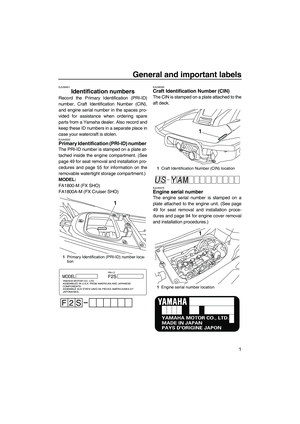 7
7 8
8 9
9 10
10 11
11 12
12 13
13 14
14 15
15 16
16 17
17 18
18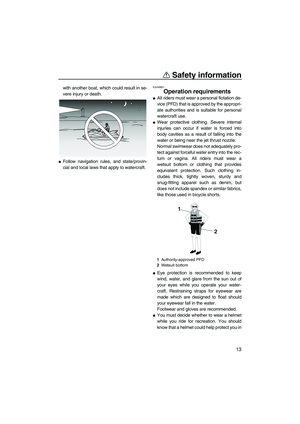 19
19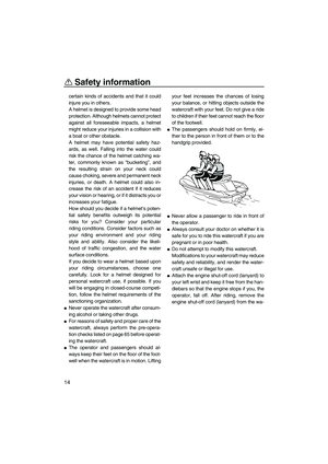 20
20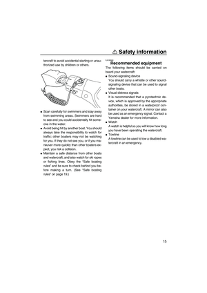 21
21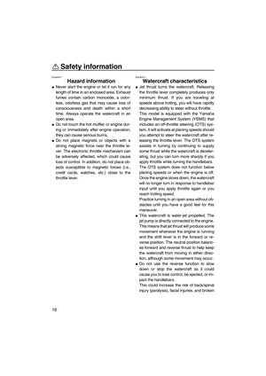 22
22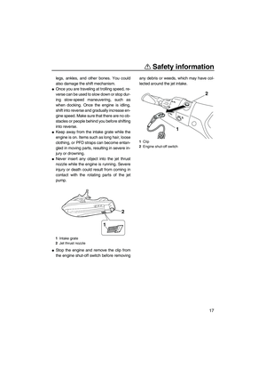 23
23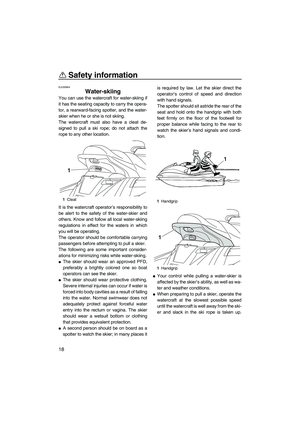 24
24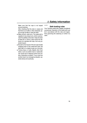 25
25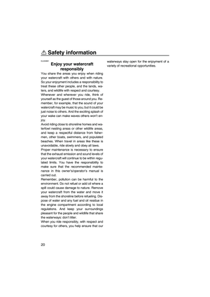 26
26 27
27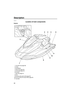 28
28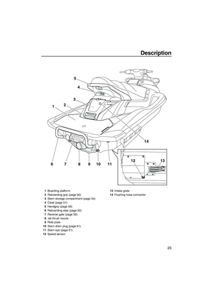 29
29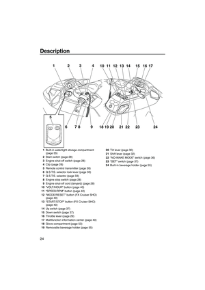 30
30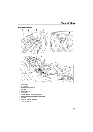 31
31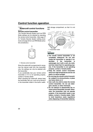 32
32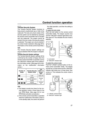 33
33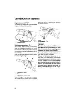 34
34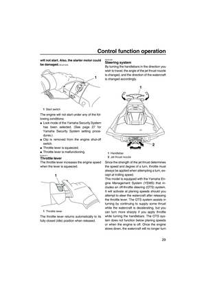 35
35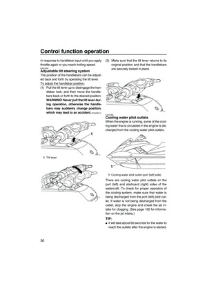 36
36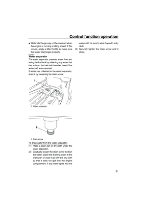 37
37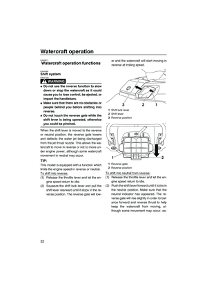 38
38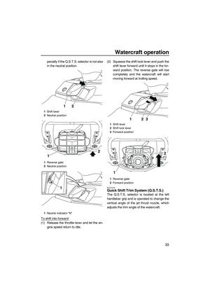 39
39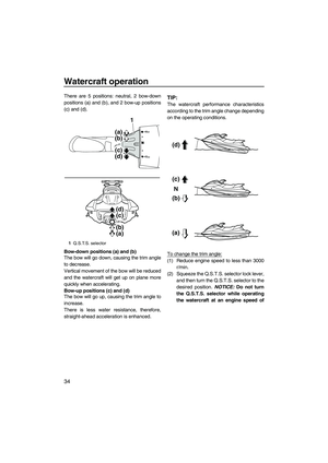 40
40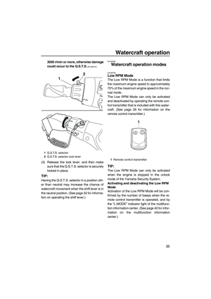 41
41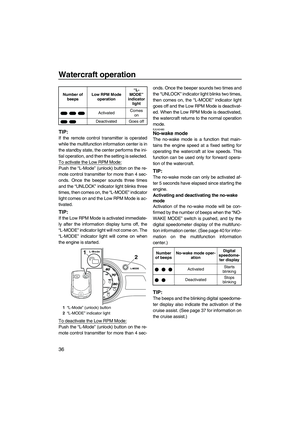 42
42 43
43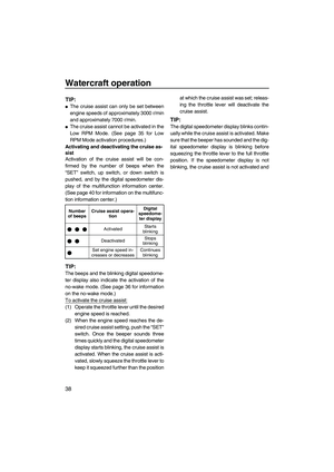 44
44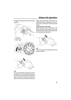 45
45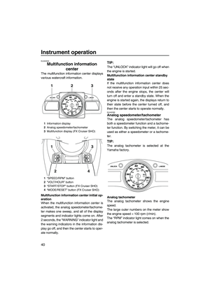 46
46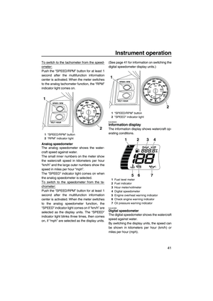 47
47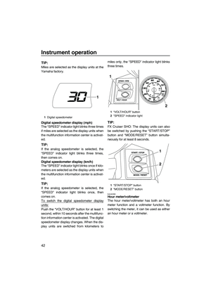 48
48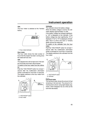 49
49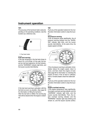 50
50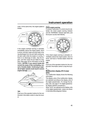 51
51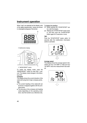 52
52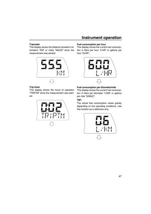 53
53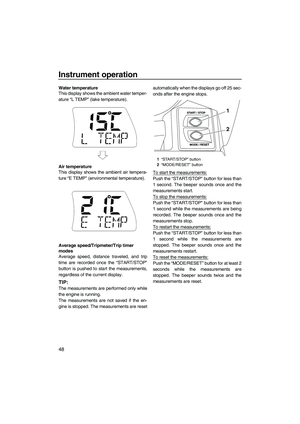 54
54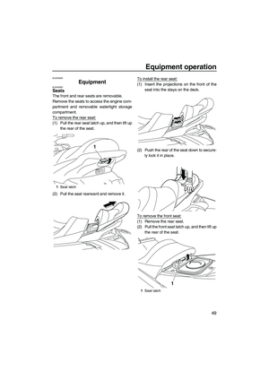 55
55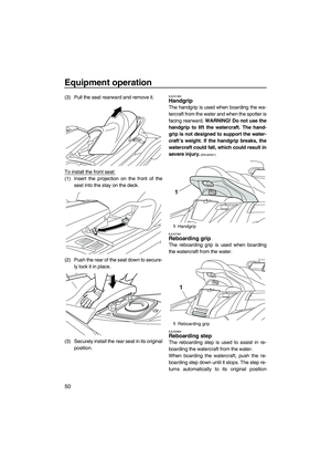 56
56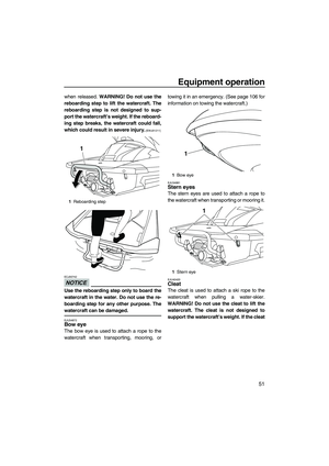 57
57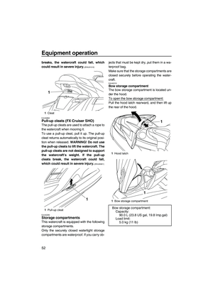 58
58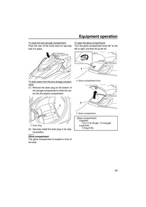 59
59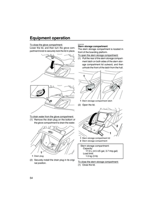 60
60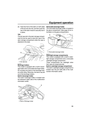 61
61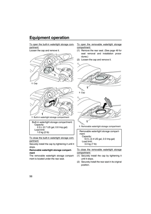 62
62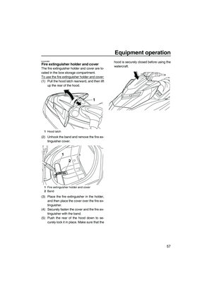 63
63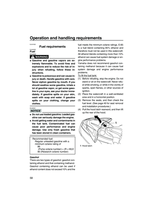 64
64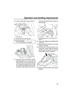 65
65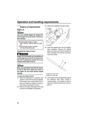 66
66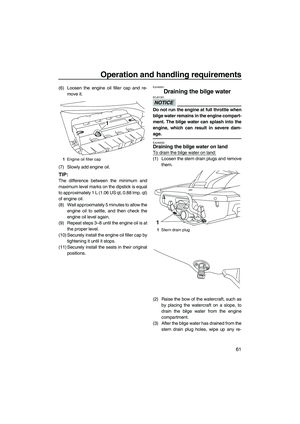 67
67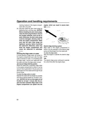 68
68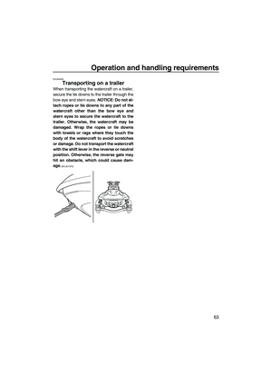 69
69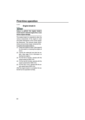 70
70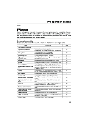 71
71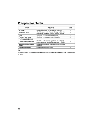 72
72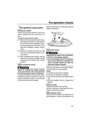 73
73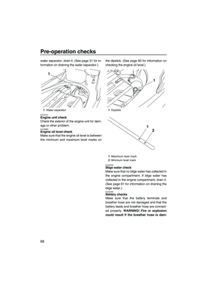 74
74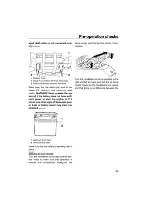 75
75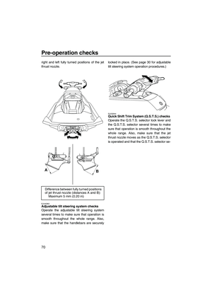 76
76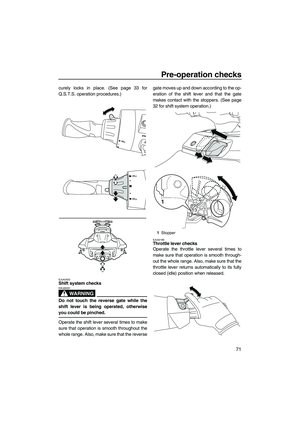 77
77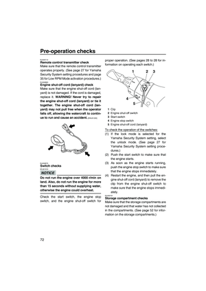 78
78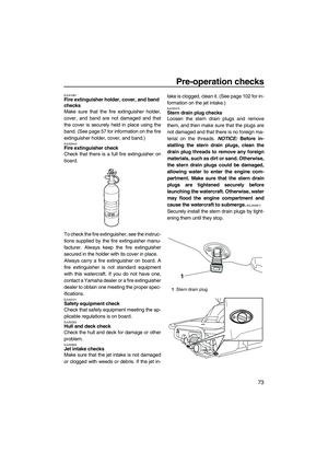 79
79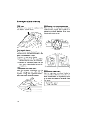 80
80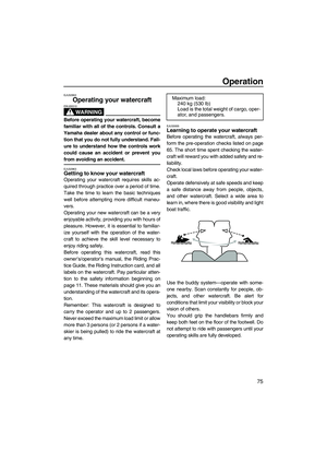 81
81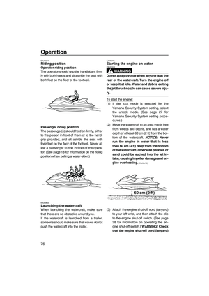 82
82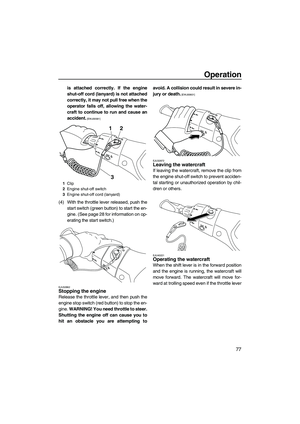 83
83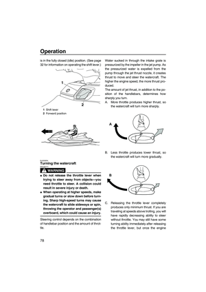 84
84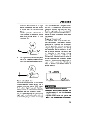 85
85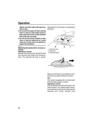 86
86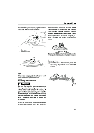 87
87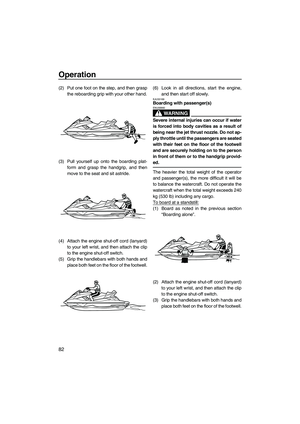 88
88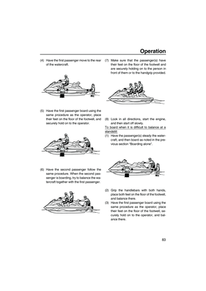 89
89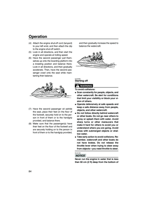 90
90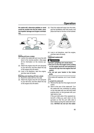 91
91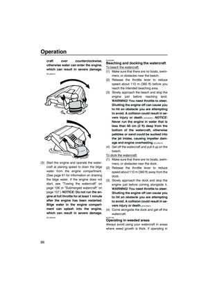 92
92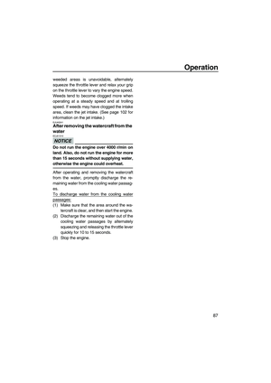 93
93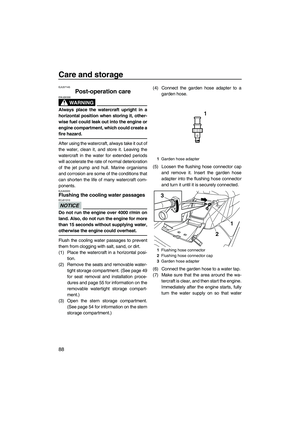 94
94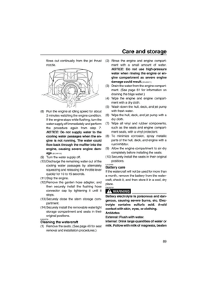 95
95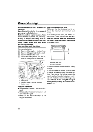 96
96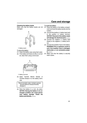 97
97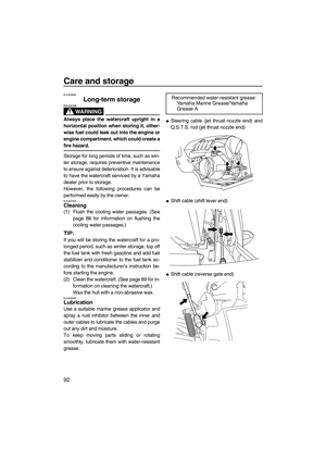 98
98 99
99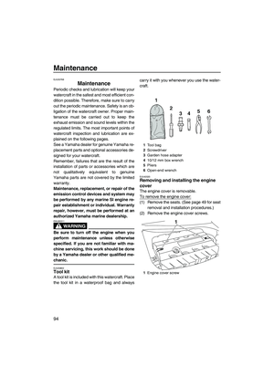 100
100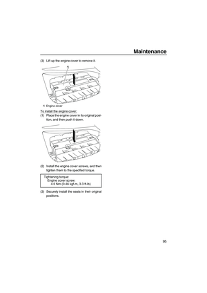 101
101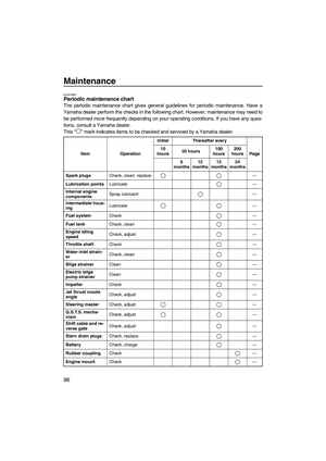 102
102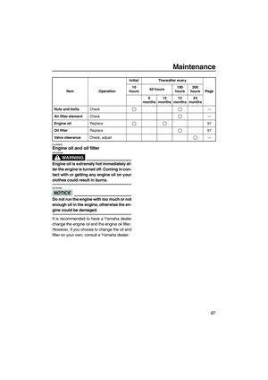 103
103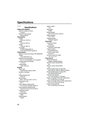 104
104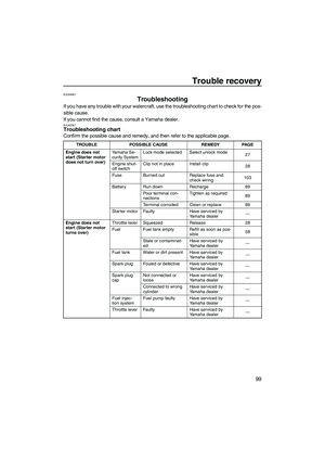 105
105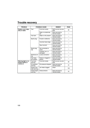 106
106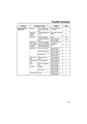 107
107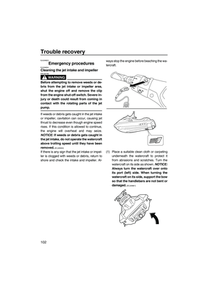 108
108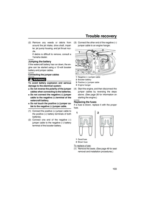 109
109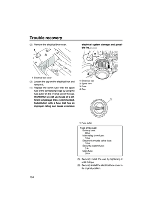 110
110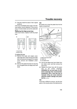 111
111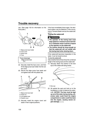 112
112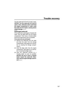 113
113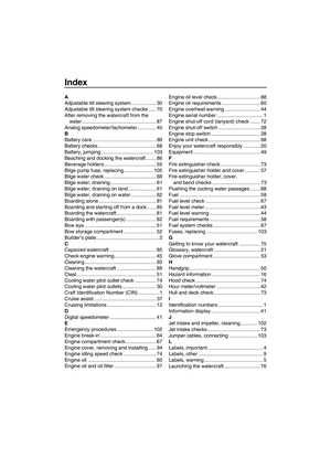 114
114 115
115 Remove the electrical box cover.
(3) Loosen the cap on the electrical box andremove it.
(4) Replace the blown fuse with the spare fuse of the correct amperage by using the
fus")